

Page 1
Where Do I Find Everything I Need for
Process Measurement and Control?
OMEGA…Of Course!
TEMPERATURE
MU
Thermocouple, RTD & Thermistor Probes,
Connectors, Panels & Assemblies
MU
Wire: Thermocouple, RTD & Thermistor
MU
Calibrators & Ice Point References
MU
Recorders, Controllers & Process Monitors
MU
Infrared Pyrometers
PRESSURE, STRAIN AND FORCE
MU
Transducers & Strain Gauges
MU
Load Cells & Pressure Gauges
MU
Displacement Transducers
MU
Instrumentation & Accessories
FLOW/LEVEL
MU
Rotameters, Gas Mass Flowmeters & Flow Computers
MU
Air Velocity Indicators
MU
Turbine/Paddlewheel Systems
MU
Totalizers & Batch Controllers
pH/CONDUCTIVITY
MU
pH Electrodes, Testers & Accessories
MU
Benchtop/Laboratory Meters
MU
Controllers, Calibrators, Simulators & Pumps
MU
Industrial pH & Conductivity Equipment
DATA ACQUISITION
MU
Data Acquisition & Engineering Software
MU
Communications-Based Acquisition Systems
MU
Plug-in Cards for Apple, IBM & Compatibles
MU
Datalogging Systems
MU
Recorders, Printers & Plotters
HEATERS
MU
Heating Cable
MU
Cartridge & Strip Heaters
MU
Immersion & Band Heaters
MU
Flexible Heaters
MU
Laboratory Heaters
ENVIRONMENTAL
MONITORING AND CONTROL
MU
Metering & Control Instrumentation
MU
Refractometers
MU
Pumps & Tubing
MU
Air, Soil & Water Monitors
MU
Industrial Water & Wastewater Treatment
MU
pH, Conductivity & Dissolved Oxygen Instruments
M-3769 / 0102
http://www.omega.com
e-mail: info@omega.com
®
User ’s Guide
LVU-500 Series
Ultrasonic Level T ransmitter
WARRANTY/DISCLAIMER
OMEGA ENGINEERING, INC. warrants this unit to be free of defects in materials and workmanship for a
period of 13 months from date of purchase. OMEGA Warranty adds an additional one (1) month grace
period to the normal one (1) year product warranty to cover handling and shipping time. This ensures
that OMEGA’s customers receive maximum coverage on each product.
If the unit should malfunction, it must be returned to the factory for evaluation. OMEGA’s Customer Service
Department will issue an Authorized Return (AR) number immediately upon phone or written request. Upon
examination by OMEGA, if the unit is found to be defective it will be repaired or replaced at no charge.
OMEGA’s WARRANTY does not apply to defects resulting from any action of the purchaser, including but not
limited to mishandling, improper interfacing, operation outside of design limits, improper repair, or unautho-
rized modification. This WARRANTY is VOID if the unit shows evidence of having been tampered with or
shows evidence of being damaged as a result of excessive corrosion; or current, heat, moisture or vibration;
improper specification; misapplication; misuse or other operating conditions outside of OMEGA’s control.
Components which wear are not warranted, including but not limited to contact points, fuses, and triacs.
OMEGA is pleased to offer suggestions on the use of its various products. However, OMEGA neither
assumes responsibility for any omissions or errors nor assumes liability for any damages that result
from the use of its products in accordance with information provided by OMEGA, either verbal or writ-
ten. OMEGA warrants only that the parts manufactured by it will be as specified and free of defects.
OMEGA MAKES NO OTHER WARRANTIES OR REPRESENTATIONS OF ANY KIND WHATS0EVER,
EXPRESSED OR IMPLIED, EXCEPT THAT OF TITLE, AND ALL IMPLIED WARRANTIES INCLUDING ANY
WARRANTY OF MERCHANTABILITY AND FITNESS FOR A PARTICULAR PURPOSE ARE HEREBY DIS-
CLAIMED. LIMITATION OF LIABILITY: The remedies of purchaser set forth herein are exclusive and the
total liability of OMEGA with respect to this order, whether based on contract, warranty, negligence,
indemnification, strict liability or otherwise, shall not exceed the purchase price of the component
upon which liability is based. In no event shall OMEGA be liable for consequential, incidental or spe-
cial damages.
CONDITIONS: Equipment sold by OMEGA is not intended to be used, nor shall it be used: (1) as a “Basic
Component” under 10 CFR 21 (NRC), used in or with any nuclear installation or activity; or (2) in medical
applications or used on humans. Should any Product(s) be used in or with any nuclear installation or activity,
medical application, used on humans, or misused in any way, OMEGAassumes no responsibility as set forth
in our basic WARRANTY/ DISCLAIMER language, and additionally, purchaser will indemnify OMEGA and
hold OMEGA harmless from any liability or damage whatsoever arising out of the use of the Product(s) in
such a manner.
RETURN REQUESTS / INQUIRIES
Direct all warranty and repair requests/inquiries to the OMEGA Customer Service
Department. BEFORE RETURNING ANY PRODUCT(S) TO OMEGA, PURCHASER MUST
OBTAIN AN AUTHORIZED RETURN (AR) NUMBER FROM OMEGA’S CUSTOMER SERVICE
DEPARTMENT (IN ORDER TO AVOID PROCESSING DELAYS). The assigned AR number
should then be marked on the outside of the return package and on any correspondence.
The purchaser is responsible for shipping charges, freight, insurance and proper packaging
to prevent breakage in transit.
FOR WARRANTY RETURNS, please have
the following information available BEFORE
contacting OMEGA:
1. P.O. number under which the product
was PURCHASED,
2. Model and serial number of the product
under warranty, and
3. Repair instructions and/or specific
problems relative to the product.
FOR NON-WARRANTY REPAIRS,
consult
OMEGA for current repair charges. Have
the following information available
BEFORE contacting OMEGA:
1. P.O. number to cover the COST
of the repair,
2. Model and serial number of product, and
3. Repair instructions and/or specific
problems relative to the product.
OMEGA’s policy is to make running changes, not model changes, whenever an improvement is possible.
This affords our customers the latest in technology and engineering.
OMEGA is a registered trademark of OMEGA ENGINEERING, INC.
© Copyright 1996 OMEGA ENGINEERING, INC. All rights reserved. This document may not be copied,
photocopied, reproduced, translated, or reduced to any electronic medium or machine-readable form, in whole or
in part, without prior written consent of OMEGA ENGINEERING, INC.
USA
MADE
IN
Servicing North America:
USA: One Omega Drive, Box 4047
ISO 9001 Certified Stamford, CT 06907-0047
Tel: (203) 359-1660 FAX: (203) 359-7700
e-mail: info@omega.com
Canada: 976 Bergar
Laval (Quebec) H7L 5A1
Tel: (514) 856-6928 FAX: (514) 856-6886
e-mail: canada@omega.com
For immediate technical or application assistance:
USA and Canada: Sales Service: 1-800-826-6342 / 1-800-TC-OMEGA
SM
Customer Service: 1-800-622-2378 / 1-800-622-BEST
SM
Engineering Service: 1-800-872-9436 / 1-800-USA-WHEN
SM
TELEX: 996404 EASYLINK: 62968934 CABLE: OMEGA
Mexico and
Latin America:
Tel: (95) 800-TC-OMEGA
SM
FAX: (95) 203-359-7807
En Espan˜ol: (203) 359-1660 ext: 2203 e-mail: espanol@omega.com
Servicing Europe:
Benelux: Postbus 8034, 1180 LAAmstelveen, The Netherlands
Tel: (31) 20 6418405 FAX: (31) 20 6434643
Toll Free in Benelux: 06 0993344
e-mail: nl@omega.com
Czech Republic: Ostravska 767, 733 01 Karvina
Tel: 42 (69) 6311899 FAX: 42 (69) 6311114
e-mail: czech@omega.com
France: 9, rue Denis Papin, 78190 Trappes
Tel: (33) 130-621-400 FAX: (33) 130-699-120
Toll Free in France: 0800-4-06342
e-mail: france@omega.com
Germany/Austria: Daimlerstrasse 26, D-75392 Deckenpfronn, Germany
Tel: 49 (07056) 3017 FAX: 49 (07056) 8540
Toll Free in Germany: 0130 11 21 66
e-mail: germany@omega.com
United Kingdom: 25 Swannington Road, P.O. Box 7, Omega Drive,
ISO 9002 Certified Broughton Astley, Leicestershire, Irlam, Manchester,
LE9 6TU, England M44 5EX, England
Tel: 44 (1455) 285520 Tel: 44 (161) 777-6611
FAX: 44 (1455) 283912 FAX: 44 (161) 777-6622
Toll Free in England: 0800-488-488
e-mail: uk@omega.com
OMEGAnet
SM
On-Line Service Internet e-mail
http://www.omega.com info@omega.com
It is the policy of OMEGA to comply with all worldwide safety and EMC/EMI regulations that apply. OMEGA is constantly
pursuing certification of its products to the European New Approach Directives. OMEGA will add the CE mark to every
appropriate device upon certification.
The information contained in this document is believed to be correct but OMEGA Engineering, Inc. accepts no liability for any errors it con-
tains, and reserves the right to alter specifications without notice.
WARNING: These products are not designed for use in, and should not be used for, patient connected applications.
I
P
65
®
®
omega.com
Page 2
Step One
SPECIFICATIONS
Range: 1.5 to 40 feet (.5 to 12.2 m)
Accuracy: ± 0.25% of span (air)
Resolution: 0.125” (3 mm)
Frequency: 26 kHz
Pulse rate: 8 pulses per second
Beam width: 4°
Blocking distance: 1.5' (.5 m) minimum
Display type: 4 segment LED
Display units: Inches
Memory: Non-volatile
Supply voltage: 14-36 VDC
Consumption: 200 mA
Current flow: Source / sink
Signal output: 4-20 mA, 14-36 VDC
Signal invert: 4-20 mA / 20-4 mA
Signal averaging: Fast / slow
Calibration: Push button
Relay type: (1) SPDT
Relay output: 250 VAC, 10A, 1/2 hp
Relay mode: Selectable, NO or NC
Relay indication: ON / OFF status
Contact resistance: 30 milliohm
Fail-safe diagnostics: Relay reverts to safe position
Temperature rating: F: -40º to 140º C: -40º to 60º
Temp. compensation: Automatic over entire range
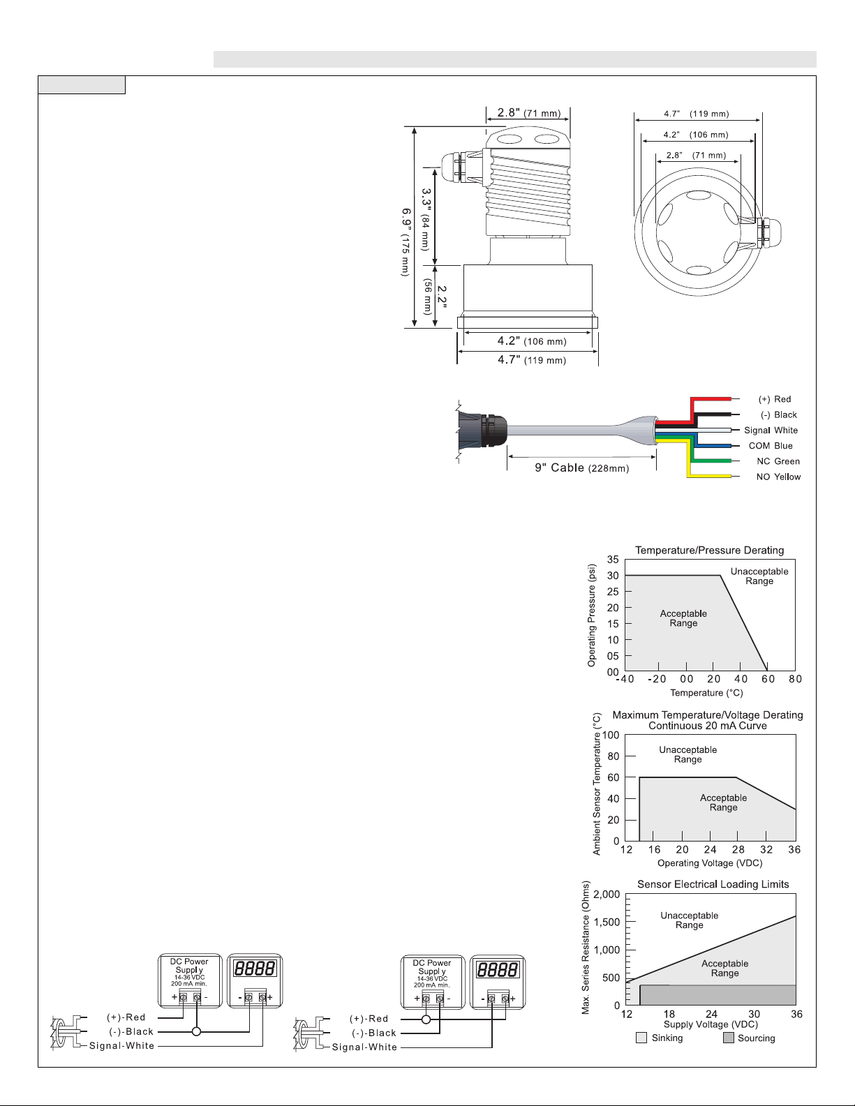
Pressure rating: 30 psi (2 bar) @ 25 °C., derated @ 1.667 psi
(.113 bar) per °C. above 25 °C.
Enclosure rating: NEMA 4X (IP65)
Enclosure material: Polypropylene, U.L. 94VO
Transducer material: Polyvinylchloride
Mounting conn.: 3” ANSI / DIN 80 flange
Conduit connection: 1/2" NPT
CE compliance: EN 50082-2 immunity
EN 55011 emission
EN 61010-1 safety
Technology
An ultrasonic sound wave is pulsed eight times per second from the
base of the transducer. The sound wave reflects against the process
medium below and returns to the transducer. The microprocessor
based electronics measure the time of flight between the sound generation and receipt, and translates this figure into the distance between
the transmitter and process medium below.
Flange not shown
Sinking vs. Sourcing
The LVU-500 series is manufactured in two different outputs, sourcing and sinking. Asourcing
transmitter uses the negative of the power supply as the reference for the entire system. When
using a sourcing unit, make sure the negative of the ground is the common for the entire system. Asinking transmitter uses the positive of the power supply as the reference for the entire
system. When using a sinking unit, make sure the positive of the ground is the common for the
entire system.
Sourcing
LVU-501
Sinking
LVU-502
Side View Top View
Page 3

Step Two Step Three
SAFETY PRECAUTIONS DEFINITIONS
About this Manual:
PLEASE READ THE ENTIRE MANUALPRIOR TO INSTALLING
OR USING THIS PRODUCT. This manual includes information on
the continuous ultrasonic level transmitter from OMEGA; LVU-500
series. Please refer to the part number located on the sensor label to verify the exact model which you have purchased.
User’s Responsibility for Safety:
OMEGA has a wide range of liquid level sensors and technologies.
While each of these technologies are designed to operate in a wide
variety of applications, it is the user’s responsibility to select a
technology that is appropriate for the application, install it properly, perform tests of the installed system, and maintain all components. The failure to do so could result in property damage or serious injury.
Proper Installation and Handling:
Because this is an electrically operated device, only properlytrained staff should install and/or repair this product. Use a proper
sealant with all installations. Never overtighten the transmitter
within the fitting. Always check for leaks prior to system start-up.
Wiring and Electrical:
A supply voltage of 14-36 VDC is used to power the LVU-500
series transmitter. The sensor systems should never exceed a maximum of 36 VDC. Electrical wiring of the sensor should be performed in accordance with all applicable national, state, and local
codes.
Temperature and Pressure:
The LVU-500 series is designed for use in application temperatures
from -40 °C (-40 °F) to 60 °C (140 °F), and for use at pressures up
to 30 psi (2 bar) @ 25 °C, derated @ 1.667 psi (.113 bar) per °C
above 25 °C.
Material Compatibility:
The continuous ultrasonic level transmitter, LVU-500 series, is
made of two materials. The enclosure is of Polypropylene (PP) and
the transducer is made of Polyvinylchloride (PVC). Make sure that
the model which you have selected is chemically compatible with
the application liquids and vapors. While the transmitter housing is
liquid-resistant when installed properly, it is not designed to be
immersed. It should be mounted in such a way that it does not normally come into contact with fluid.
Flammable, Explosive and Hazardous Applications:
The LVU-500 series level transmitter systems should not be used
within flammable or explosive applications.
Make a Fail-Safe System:
Design a fail-safe system that accommodates the possibility of
transmitter or power failure. In critical applications, OMEGA recommends the use of redundant backup systems and alarms in addition to the primary system.
EC4: The 4 mA setting for the LVU500 series. The EC4 is the distance
from the bottom of the transducer to the
4 mAset point. This setting is measured
in either inches or centimeters on the
display. The EC4 setting is typically
greater that the EC20 setting.
EC20: The 20 mAsetting for the L VU500 series. The EC20 is the distance
from the bottom of the transducer to the
20 mA set point. This setting is measured in either inches or centimeters on
the display.
RLAY: Indicator for the next two
modes. The 10A relay is latched
between the HSET and LSET points.
HSET & LSET: Sets the high point
and low point for relay activation.
Relay will energize when display value
is greater than the LSET value. Relay
will de-energize when display value is
less than the HSET value. The HSET
value is always less that the LSET
value. To activate the relay from a single point, set HSET and LSET to the
same value.
SAF1/SAF2: The 10A relay inside the LVU-500 series can be used
in a fail-safe design of your system. When [SAF1] is set, the relay will
de-energize when the acoustic return signal is LOST . When [SAF2] is
set, the relay will energize when the acoustic return signal is LOST.
Response times will vary according to the setting of the LVU-500
series ([FAST] or [SLOW] modes).
FAST/SLOW: FAST and SLOW sets the reaction time for the
SAF1/2 setting. [FAST] is the typical setting for the LVU-500 series
to operate. The time for the RELAY to default is 30 seconds for the
[FAST] mode and 2.5 minutes for the [SLOW] mode.
ALIN: Indicates that the unit is in the Alignment mode. Display will
show the return signal strength in dB’s. Used as an indicator for
mechanical alignment of the LVU-500 series and/or signal attenuation. Typical readings range between 2 and 60 dB’s. For optimum
alignment, first energize the unit and receive a valid return signal.
Then select the ALIN mode and adjust the LVU-500 series until the
value is maximized.
ON/OFF: Actual setting for ALIN
mode. The ALIN mode must be turned
[OFF] when alignment is completed.
This mode will not automatically default
back to [LEVL].
TANK: Used as an indication for
[TANK] or maximum range. The TANK
sets the maximum tank height and will
filter out all acoustic signal returns
greater than this value.
(value): Actual TANK setting. The
maximum distance is 480.0 inches.
Warning
The LVU-501 is a sourcing transmitter which provides internal
4-20 mA excitation and should be used with a sinking device.
The LVU-502 is a sinking transmitter which requires external 420 mA excitation and should be used with a sourcing device.
All measurement values used for programming the LVU-500
series are made from the bottom of the transmitter down to the
liquid surface.
Page 4

Step Four Step Five
PROGRAMMING WIRING
EC4:
1. Hold [MENU] key until EC4 appears in display.
2. Release [MENU] key and wait until a value appears. This value is
the current measured level value.
3. If this is acceptable, press [SET] to lock the value as the new EC4
set point. If not, press either the [
s ] or [t ] keys once and the old
setting for the EC4 will appear.
4. From here, use the [s ] or [t ] keys to raise or lower the value to
the desired value.
5. Press the [SET] key to enter this value as the new EC4 set point.
EC20:
1. Hold [MENU] key until EC20 appears in display.
2. Release [MENU] key and wait until a value appears. This value is
the current measured level value.
3. If this is acceptable, press [SET] to lock the value as the new
EC20 set point. If not, press either the [s ] or [t ] keys once and
the old setting for the EC20 will appear.
4. From here, use the [s ] or [t ] keys to raise or lower the value to
the desired value.
5. Press the [SET] key to enter this value as the new EC20 set point.
HSET/LSET:
1. Hold [MENU] key until HSET or LSET appears in the display.
2. Release [MENU] key wait for the display to change to a number.
3. From here, use the [s ] or [t ] keys to raise or lower the value to
the desired value.
4. Release all buttons and the value will be entered into memory. The
[SET] button does not need to be pressed.
5. Repeat process for the other setting.
SAF1/SAF2:
1. Hold [MENU] key until SAF1 or SAF2 appears in the display.
2. Release [MENU] key and hold [SET] key to toggle between
SAF1 and SAF2.
3. When desired setting is reached, release [SET] key. The last dis-
played setting will be locked into memory. To change, start again
at step 1.
FAST/SLOW:
1. Hold [MENU] key until FAST or SLOW appears in the display.
2. Release [MENU] key and hold [SET] key to toggle between
FAST and SLOW.
3. When desired setting is reached, release [SET] key. The last dis-
played setting will be locked into memory. To change, start again
at step 1.
ALIN:
1. Hold [MENU] key until ALIN appears in the display.
2. Continue to hold [MENU] key until OFF appears in the display.
3. Release [MENU] key and hold [SET] key to toggle from OFF to
ON.
4. Release [SET] key. The LVU-500 is now in ALIN mode.
5. To exit ALIN mode, repeat steps 1-4 changing from ON to OFF.
TANK:
1. Hold [MENU] key until TANK appears in the display.
2. Continue to hold [MENU] key until a value appears in the display.
This value is the current TANK setting.
3. If this is acceptable, press [SET] to lock the value as the TANK
setting. If not, use the [s ] or [t ] keys to raise or lower the value
to the desired setting.
4. Press the [SET] key to enter this value as the new TANK setting.
The LVU-500 series requires 14-36 VDC power with at least a 200
mA supply in order to operate.
1. Wiring to a OMEGA Continuous Controller (LVCN-51):
2. Wiring to a Two-Wire Loop Indicator (LVU-502 only):
3. Wiring to a Two-Wire Loop Indicator (LVU-501 only):
4. Wiring to a PLC (LVU-502 only):
5. Wiring to a PLC (LVU-501 only):
Page 5

Step Six Step Seven
INSTALLATION INSTALLATION
Flange Mounting:
Flange mounting of the LVU-500 series should be done in accordance with all applicable ANSI or DIN installation standards.
Flange Riser Compatibility:
The LVU-500 series should not be installed in flange risers that are
tall enough to interfere with the acoustic signal path. The chart below
indicates the maximum height at which the LVU-500 series can be
installed based on the flange riser ID. For example, if the flange riser
ID is 4”, then the flange riser height should be no more than 7”. The
flange riser height is defined as the distance from the bottom of the
transducer to the opening in the tank.
Factory Settings:
The LVU-500 series transmitter is preset at the factory. When powering up the sensor the first time, the factory settings will be active. If
at any time in you need to return to these settings, remove power from
the sensor and wait 10 seconds. Press the [Set] and [Menu] buttons
simultaneously while powering up the sensor.
Depth Radius Radius
(Feet) (Inches) (cm)
1 1.59 4.04
2 2.43 6.17
3 3.27 8.30
4 4.11 10.43
5 4.95 12.56
6 5.78 14.69
7 6.62 16.82
8 7.46 18.96
9 8.30 21.09
10 9.14 23.22
11 9.98 25.35
12 10.82 27.48
13 11.66 29.61
14 12.50 31.74
15 13.34 33.88
16 14.18 36.01
17 15.02 38.14
18 15.85 40.27
19 16.69 42.40
20 17.53 44.53
Depth Radius Radius
(Feet) (Inches) (cm)
21 18.37 46.66
22 19.21 48.80
23 20.05 50.93
24 20.89 53.06
25 21.73 55.19
26 22.57 57.32
27 23.41 59.45
28 24.25 61.58
29 25.08 63.71
30 25.92 65.85
31 26.76 67.98
32 27.60 70.11
33 28.44 72.24
34 29.28 74.37
35 30.12 76.50
36 30.96 78.63
37 31.80 80.77
38 32.64 82.90
39 33.48 85.03
40 34.31 87.16
Maximum Application Range:
The LVU-500 series maximum range of transmitter is 40.0 feet. Yet a
number of factors can reduce the overall quality of signal return and
shorten the accurate range of the transmitter. To determine the maximum application range of the product, follow the signal return formula against the echo attenuation graph below.
Echo Attenuation Range:
I.D.
(Inches) (cm)
Flange Riser
3 7.6
4 10.2
5 12.7
6 15.2
7 17.8
8 20.3
3 7.6
7 17.8
11 27.9
15 38.1
19 48.3
26 66.0
Height
(Inches) (cm)
Avoid interfer-
ence from side
of tank
Do not
install at an
angle
Avoid inter-
ference from
obstructions
in tank
Transmitter
will not oper-
ate in vacuum
Changing Display Units:
The LVU-500 series come preset to measure in inches. T o change the
unit of measurement to centimeters, remove power and wait 10 seconds. Press [
s ] and [Set] simultaneously while powering up the
transmitter. The LVU-500 series will now read in centimeters. To
return to inches, remove power and wait 10 seconds. Press [t ] and
[Set] simultaneously while powering up the transmitter.
Page 6

Step Eight Step Nine
INSTALLATION MAINTENANCE
LOST Signal:
A reading of LOST in the display of the LVU-500 series indicates the
transmitter is not receiving a valid acoustic return signal. If LOST
appears, please check the following troubleshooting items:
1. Beam cone interference such as the side wall, ladders, seams,
rungs or pipes within the LVU-500 series's acoustic signal path.
2. Proper installation such that the LVU-500 series is installed level
and free from interference from the installation flange.
3. Sufficient power being supplied to the LVU-500 series. The LVU500 series requires 14-36 VDC power with a minimum supply of
200 mA.
4. Proper programming of the TANK function. The TANK function
is often set as the distance from the bottom of the tank to the bottom of the transmitter.
5. Make sure that the transmitter is not installed at an angle. Even a
3 degree offset can reduce the signal return strength greatly.
Current is always 4mA or 20 mA:
If the output of the LVU-500 series is always reading 4mA or 20 mA,
check the input values for the LVU-500 series. The display of the
LVU-500 series reads to the 1/10 of an inch. A display of 1234 is
123.4" and not 1234".
EC4 and EC20 Set Points:
When checking the EC4 and EC20 set points, the first value which
appears after EC4 or EC20 is the current distance from the bottom of
the transmitter to the surface of the liquid. Pressing either the [s ] or
[t ] buttons will then show the actual set point in memory.
General:
The LVU-500 series transmitter itself requires no periodic maintenance except cleaning as required. It is the responsibility of the user
to determine the appropriate maintenance schedule, based on the specific characteristics of the application.
Cleaning Procedure:
1. Power: Make Sure that all power to the sensor, controller and/or
power supply is completely disconnected.
2. Sensor Removal: In all through-wall installations, make sure
that the tank is drained well below the sensor prior to removal.
Carefully, remove the sensor from the installation.
3. Cleaning the Sensor: Use a soft bristle brush and mild deter-
gent, carefully wash the LVU-500 series transmitter. Do not use
harsh abrasives such as steel wool or sandpaper, which might
damage the surface sensor. Do not use incompatible solvents
which may damage the LVU-500 series's Polypropylene or PVC
plastic body.
4. Sensor Installation: Follow the appropriate steps of installa-
tion as outlined in the installation section of this manual.
Internal Relay:
The LVU-500 series contains a 250 VAC, 10A, 1/2 Hp internal relay.
The relay is actuated by the HSET and LSET settings. While this
manual offers some examples and suggestions to help explain the
operation of the relay, such examples are for information only and are
not intended as a complete guide to installing any specific system.
High Level Alarm:
The goal is to make sure the
liquid does not rise above a
certain point. If it does, an
alarm sounds alerting the operator to a high level
condition. Wire the hot lead of the alarm to the Green
NC relay wire. Also make sure the HSET and
LSET settings are programmed correctly.
Typically the values are set at the same distance
away from the LVU-500 series. In the normal
operation state, the LVU-500 series’s
relay will remain energized, keeping the
alarm circuit open. When the alarm
level has been reached, the relay deenergizes and activates the alarm. To
change to a low level alarm, re-wire the
alarm from the Green NC wire to the
Yellow NO wire.
Automatic Fill:
The goal is to fill the tank. A
valve is opened (energized)
when a low level is reached
and closed (de-energized)
when a high level is reached. Wire the hot lead of the
valve to the Yellow NO relay wire. Make
sure the HSET and LSET settings are
programmed correctly. Typically the values are set with the HSET as the valve
close and the LSET as the valve open. A
pump or solenoid can be substituted for
the exact same operation. When the low
level is reached, the system will start to
fill the tank. The tank will continue to
fill until the level reaches the high point.
The system stops filling until the low
level is reached again. To change to an
automatic empty application, re-wire
the system from the Yellow NO wire the
the Green NC wire.
 Loading...