

Page 1
omega.com
e-mail: info@omega.com
For latest product manuals:
omegamanual.info
LVU30 Series Ultrasonic Sensors
Installation and Operation Guide
Shop online at
User’s Guide
Page 2

Servicing North America:
U.S.A.: One Omega Drive, P.O. Box 4047
ISO 9001 Certified Stamford, CT 06907-0047
TEL: (203) 359-1660
FAX: (203) 359-7700
e-mail: info@omega.com
Canada: 976 Bergar
Laval (Quebec) H7L 5A1, Canada
TEL: (514) 856-6928
FAX: (514) 856-6886
e-mail: info@omega.ca
For immediate technical or application assistance:
U.S.A. and Canada: Sales Service: 1-800-826-6342/1-800-TC-OMEGA
®
Customer Service: 1-800-622-2378/1-800-622-BEST
®
Engineering Service: 1-800-872-9436/1-800-USA-WHEN
®
Mexico: En Espan˜ ol: (001) 203-359-7803
e-mail: espanol@omega.com
FAX: (001) 203-359-7807
info@omega.com.mx
Servicing Europe:
Czech Republic: Frystatska 184, 733 01 Karviná, Czech Republic
TEL: +420 (0)59 6311899
FAX: +420 (0)59 6311114
Toll Free: 0800-1-66342
e-mail: info@omegashop.cz
Germany/Austria: Daimlerstrasse 26, D-75392 Deckenpfronn, Germany
TEL: +49 (0)7056 9398-0
FAX: +49 (0)7056 9398-29
Toll Free in Germany: 0800 639 7678
e-mail: info@omega.de
United Kingdom: One Omega Drive, River Bend Technology Centre
ISO 9002 Certified Northbank, Irlam, Manchester
M44 5BD United Kingdom
TEL: +44 (0)161 777 6611
FAX: +44 (0)161 777 6622
Toll Free in United Kingdom: 0800-488-488
e-mail: sales@omega.co.uk
OMEGAnet®Online Service Internet e-mail
omega.com info@omega.com
It is the policy of OMEGA Engineering, Inc. to comply with all worldwide safety and EMC/EMI
regulations that apply. OMEGA is constantly pursuing certification of its products to the European New
Approach Directives. OMEGA will add the CE mark to every appropriate device upon certification.
The information contained in this document is believed to be correct, but OMEGA accepts no liability for any
errors it contains, and reserves the right to alter specifications without notice.
WARNING: These products are not designed for use in, and should not be used for, human applications.
Page 3

TABLE OF CONTENTS
Section Page
1 Introduction ........................................................................................................ 1
2 Quick Guide on Getting Started ..................................................................... 2
Mounting the Sensor ........................................................................................................................ 2
Operating an Sensor Without a Computer .................................................................................. 2
Operating an Sensor Connected to a Computer ........................................................................ 3
Operating Up to 32 Sensors Simultaneously Using a Multi-Drop Configuration ................. 5
3 Product Description ......................................................................................... 6
DC Power Requirements .................................................................................................................. 6
Voltage Output (V-out) of a Sensor ............................................................................................... 6
RS485 Port ............................................................................................................................................ 8
4 Installing LVU30 Series Software ................................................................... 10
5 Status and Setup Screen .................................................................................. 11
Establishing Communication between a PC and the Sensor ..................................................... 11
Editing the Sensor Parameters ......................................................................................................... 12
Sensor Selection Box of the Status and Setup Screen ................................................................. 13
Status Box of the Status and Setup Screen .................................................................................... 14
Mode Selection for Output Voltage Box of the Status and Setup Screen ............................... 15
Sampling Settings Box of the Status and Setup Screen ............................................................... 17
Miscellaneous Box of the Status and Setup Screen ..................................................................... 18
Messages Box of the Status and Setup Screen .............................................................................. 19
Self Heating Correction ..................................................................................................................... 19
Calibration of the Voltage Output .................................................................................................. 20
Displaying the Ultrasonic Signal ...................................................................................................... 21
Overview of Main Drop Down Menus of the Status and Setup Screen Settings ................... 23
6 Factory Default Programmed Settings ........................................................... 27
7 Troubleshooting ................................................................................................ 28
8 Terminology ........................................................................................................ 28
9 Wire Color Code ................................................................................................ 30
i
Page 4

1 Introduction
In operation, an LVU30 Series Sensor generates a high frequency ultrasonic pulse, measures the time
it takes for the reflected echo to return from a target, and then calculates the target distance using the
speed of sound. The value of the speed of sound, which is a function of temperature, is determined
by the sensor using its internal temperature probe. The distance to a target can be obtained from an
LVU30 Series Sensor in a variety of ways. For example, the sensor output can be a DC voltage, the
value of which is proportional to the target distance, or the sensor can be programmed to produce a
switched voltage output at a user-determined target distance. Information regarding the target can be
sent by an RS485 communication link to a computer and displayed using the LVU30 Series Software,
or another host device can be used.
Key Features of LVU30 Series Sensors include:
• Analog or Setpoint Switched Output
• Plug & Play Setup - No Targets Needed
• Software Set Span and Zero - No Pots or Pushbuttons
®
• Easy to use Setup Software using Windows
• Built-in Temperature/Sound Speed Compensation
98 /NT/2000 / XP operating systems
• Up to 32 Sensors on RS485 Multi-drop Loop
1
Page 5
2 Quick Guide on Getting Started
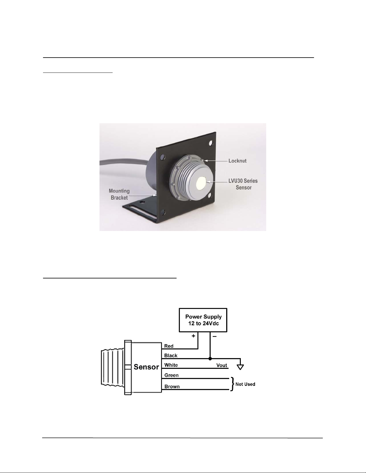
Mounting the Sensor
The LVU30 Series Family of Low Cost Sensors is designed to be easily mounted by using the 1” NPT
threaded shaft that is part of the housing of each sensor. The sensor can be screwed into a 1” NPT
tapped hole in a mounting plate, or it can be mounted onto a flat plate by inserting the threaded shaft
of the housing through a hole in the plate and securing the sensor using the locknut that is included
with each sensor. An optional Mounting Bracket can also be purchased, as shown in Figure 1.
Figure 1
Photograph of a LVU30 Series Sensor Attached to an Optional Mounting Bracket
Operating a Sensor Without a Computer
• With the 12-24 V DC Power Supply turned OFF, connect it to the red and black leads of the
Sensor, as shown in Figure 2.
Figure 2
Wiring Diagram for an LVU30 Series Sensor Used Without a Computer
2
Page 6
2 Quick Guide on Getting Started (continued)
• Turn the Power Supply ON.
• The DC voltage on the white lead of the sensor will be proportional to the distance to the
target.
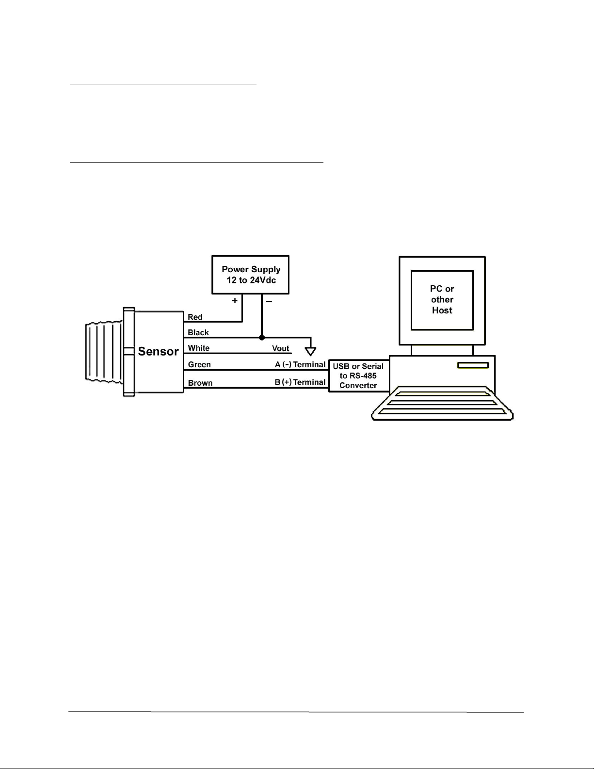
Operating an Sensor Connected to a Computer
• Download the LVU30 Series Software into the computer from the Omega website at
www.omega.com.
• With the 12-24 V DC Power Supply turned OFF, connect it to the red and black leads of the
sensor, as shown in Figure 3.
Figure 3
Wiring Diagram for an LVU30 Series Sensor Used With a Computer
• For the sensor to communicate with a computer, either an RS232/RS485 converter is
required when connecting to a serial port, or a USB/RS485 converter is required when
connecting to a USB port.
• Connect the sensor’s green lead to the converter’s A (-) terminal [the TDA (-) terminal on a
USB converter], and the brown lead to the converter’s B (+) terminal [the TDB (+) terminal
on USB converter].
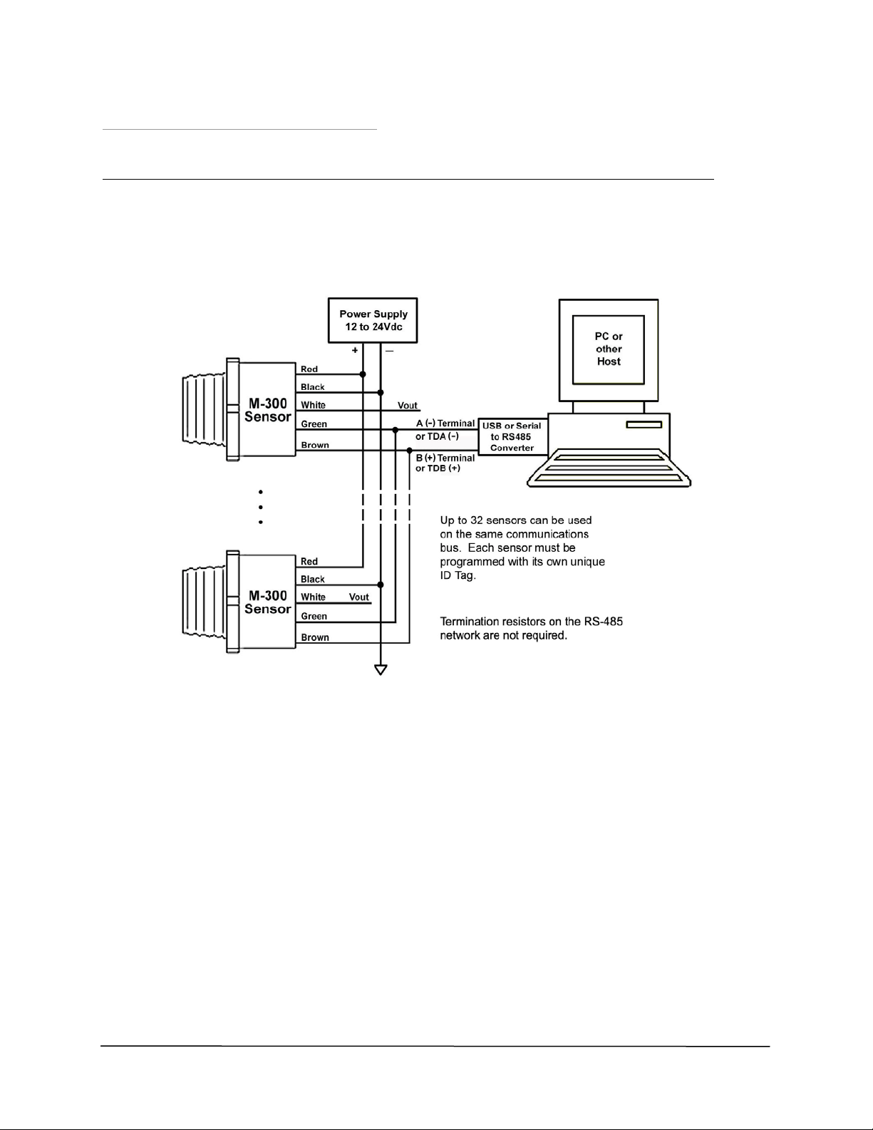
NOTE: Use of termination resistors on the RS485 network is not required.
• Plug the Communication Converter into the appropriate serial or USB port on the
Computer.
• Turn the Power Supply ON.
• Execute the LVU30 Series program.
3
Page 7
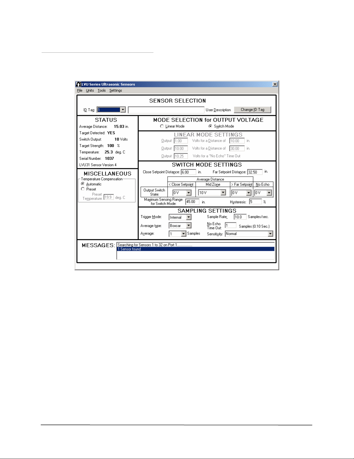
2 Quick Guide on Getting Started (continued)
• The Status and Setup Screen will appear, as shown in Figure 4, and an indication that the
sensor was “found” will appear in the ‘Messages’ box at the bottom of the screen.
Figure 4
Example of the Status and Setup Screen for an Sensor
NOTE: If the sensor is not “found”, you may have to select another communications port. Use
the drop-down menu ‘Settings’ then ‘Communications Port’ to select another port. Use
the ‘Tools’ drop-down menu and then ‘Search for Sensors’ to establish communications
on the new port.
• Point the LVU30 Series sensor towards a target, such as a wall, to obtain a distance
measurement.
• To change any of the settings, move the mouse pointer and click on the field to be
modified. After all changes have been made, click on the ‘Program’ button. There is no
limit to the number of times the sensor can be reprogrammed. The Sensor’s settings are
non-volatile and the programmed values will be retained even if power is lost.
• The sensor can be adjusted for optimum performance in each application by adjusting its
settings. (See Section 5 for detailed information regarding utilization of these adjustment
features.)
4
Page 8
2 Quick Guide on Getting Started (continued)
Operating Up to 32 Sensors Simultaneously Using a Multi-Drop Configuration
• Download the LVU30 Series Software into the Computer from the Omega Engineering
website at www.omega.com.
• With the 12-24 V DC Power Supply turned OFF, connect it to the red and black leads of the
sensor, as shown in Figure 5.
‘
Figure 5
Wiring Diagram for LVU30 Series Sensors Using a Multi-Drop Configuration
• Connect the first sensor to the Computer using the steps shown in the subsection entitled
“Operating a Sensor Connected to a Computer”, and insert a unique ID Tag from 1 to 32
into the sensor.
• Disconnect the sensor and then sequentially connect to the computer, by themselves one at
a time, each of the remaining multiple sensors that are going to be placed on the
communications bus, and insert a unique ID Tag from 1 to 32 into each of them. Once this
has been done, all the sensors can be wired in parallel to the RS485 communications bus, as
illustrated in Figure 5.
• Restart the LVU30 Series program. Any sensor can now be selected from the drop down list
next to the ID Tag and its status viewed.
• Any sensor can be reprogrammed, including changing its ID Tag, by selecting it and making
the desired changes.
5
Page 9
3 Product Description
This section contains a general overview of the LVU30 Series of Ultrasonic Sensors. For detailed
information on any specific model of sensors, refer to the datasheet located on the Omega
Engineering, Inc. website (www.omega.com) for the particular model.
DC Power Requirements
LVU30 Series Sensors are powered from 12 to 24 V DC sources, either batteries or power supplies,
that are capable of supplying currents of approximately 30 ma. The red and black wires of the sensor
must be connected to the DC power, as shown in Figures 2, 3, and 5 in Section 2.
Voltage Output (V-out) of a Sensor
The white lead of an LVU30 Series Sensor produces a DC analog Output Voltage, V-out, as shown in
Figure 2, 3, and 5 in Section 2. The value of V-out provides information regarding the Target Distance,
which is the distance from the sensor to a target. Sensors have two modes of operation. In the
Proportional Voltage Output Mode, V-out is an analog DC voltage that is directly proportional to the
Target Distance. In the Switched Setpoint Output Mode, V-out switches between two different
voltage levels based on the Target Distance falling within specific distance zones that are programmed
into the sensor as Setpoints. More detailed information regarding the use of these two operational
modes is contained in Section 5.
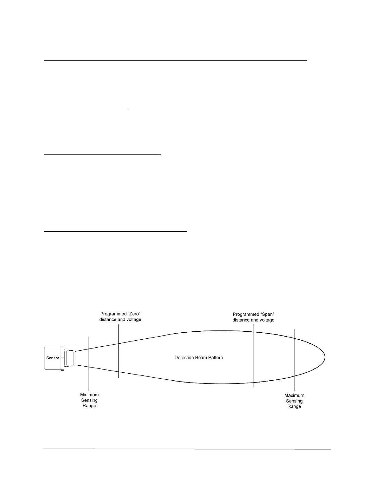
Proportional Voltage Output Mode (‘Linear Mode’)
Figure 6 is a schematic illustration of the Proportional Voltage Output Mode (‘Linear Mode’) of V-out
for an LVU30 Series Sensor. A Zero distance and a Span distance that are anywhere within the
Minimum Sensing Range and Maximum Sensing Range of the sensor can be programmed into the
sensor. The values of V-out will then be proportional to the Target Distance in the zone between the
distances set for Zero and Span. If a target is any closer than the Zero distance, V-out will be the
voltage value that was programmed into the sensor for the Zero distance. If the target is further away
than the Span distance, V-out will be the voltage value that was programmed into the Sensor for the
Span distance. If no target is detected, than V-out will be a third voltage, which is programmed as the
Loss of Echo Voltage.
Figure 6
Schematic Illustration of the Proportional Voltage Output Mode of V-out for an LVU30 Series Sensor
6
Page 10
3 Product Description (continued)
In the ‘Linear Mode’, the user can set the values for the following programming options using the
Status and Setup Screen shown in Figure 4 in Section 2 on Page 4.
1) Set any Output Voltage value from 0 V DC to 10.25 V DC for the Zero Distance
2) Set any Output Voltage value from 0 V DC to 10.25 V DC for the Span Distance
3) Set any Output Voltage value from 0 V DC to 10.25 V DC for the No Echo Time Out to indicate that
the target is “lost”, which occurs after the preset number of samples that were programmed into
the ‘No Echo Time Out’ in the ‘Sampling Settings’.
With this flexibility, positive or negative slopes can be programmed, along with any start and end
voltage value. Targets within the detection zone, established by the Zero and Span distances, will
produce an output voltage that is proportional to the Target Distance between the Zero Output
Voltage and the Span Output Voltage. Targets detected beyond the endpoints of the selected
distance zone will produce output voltages equal to the nearer endpoint. Targets detected closer
than the minimum specified Sensing Range will produce a V-out equal to the Outpoint Voltage
programmed for the Zero distance. Targets detected at distances greater than the programmed Span
distance will produce a V-out equal to the Outpout Voltage programmed for the Span distance. If no
target is detected, V-out will be the Output Voltage programmed for ‘No Echo Time Out’.
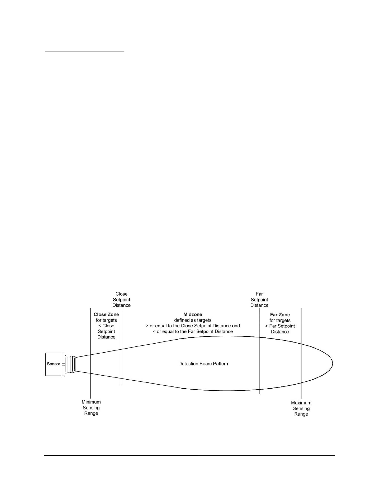
Switched Setpoint Output Mode (‘Switch Mode’)
Figure 7 is a schematic illustration of the Switched Setpoint Output Mode (‘Switch Mode’) of V-out for
an LVU30 Series Sensor. In this Switch Mode, a Close Setpoint Distance and a Far Setpoint Distance,
that are anywhere within the Minimum and Maximum Sensing Range, can be programmed into the
sensor. These two setpoint distances will then establish three distance zones, which are the CIose
Zone for Target Distances less than the Close Setpoint Distance, the Mid Zone for target distances
between the Close Setpoint Distance and the Far Setpoint Distance, and the Far Zone for Target
Distances greater than the Far Setpoint Distance. Different value of V-out can be selected to be
produced for when the target is located in each of the three zones.
Figure 7
Schematic Illustration of the Switched Setpoint Output Mode of V-out for an LVU30 Series Sensor
7
Page 11

3 Product Description (continued)
In the ‘Switch Mode’, the user can set the value of the following programming options using the
Status and Setup Screen shown in Figure 4 in Section 2 on Page 4.
1) Set a value for the Close Setpoint Distance.
2) Set a value for the Far Setpoint Distance.
3) Set a value of 0 V DC or 10.25 V DC for V-out when the Target Distance is in the Close Zone
(<Close Setpoint Distance).
4) Set a value of 0 V DC or 10.25 V DC for V-out when the Target Distance is in the Mid Zone (>Close
Setpoint Distance and <Far Setpoint Distance).
5) Set a value of 0 V DC or 10.25 V DC for V-out when the Target Distance is in the Far Zone (>Far
Setpoint Distance).
6) Set a value of 0 V DC or 10.25 V DC for when No Echo has been detected after a preset timeout.
7) The Mid Zone also has a ‘No Change’ programmable option where the value of V-out will not
charge when a target enters this zone from another zone.
8) Hysteresis around the setpoints can be programmed from 0% to 75%.
9) V-out for targets detected closer than the minimum specified Sensing Range of the specific model
of LVU30 Series Sensor used will be the same as the value for V-out set for the Close Zone.
RS485 Port
Monitoring and programming the sensor occurs through the RS485 serial communications port. The
advantages of an RS485 based system include the ability to have long cable lengths while wiring up to
32 sensors on just one pair of wires (multi-drop). This method allows for access to all sensors from
any convenient location. When communicating with a PC, a communications converter will be
required (either a USB or RS232 to RS485).
Wire the sensor to the RS485 Communication Converter as shown in Figure 3 in Section 2. The
converter’s terminal for the green wire of the sensor will be marked as TDA, A (-), or some
combination for the A terminal wiring. The converter’s terminal for the brown wire of the sensor will
be marked as TDB, B (+), or some combination for the B terminal wiring. If the converter has any of
the switches shown below, set to the following positions:
• TD 422 or TD 485, set to TD 485 position
• ECHO ON or ECHO OFF, set to ECHO OFF position
• 4 Wire or 2 Wire, set to 2 Wire position
The sensor is now ready to communicate using the LVU30 Series Software Program.
8
Page 12

3 Product Description (continued)
Multi-drop Operation
When planning to connect more than one sensor on the same communications bus, each must be
programmed with its own unique ‘ID Tag’ from 1 to 32. To do this, only one sensor at a time must be
placed and each is then programmed with its own unique ‘ID Tag’. The available ‘ID Tag’ numbers are
1 to 32. Repeat this procedure for all the sensors on the communications port.
The software will now allow the monitoring and editing of any sensor on-line. To monitor any sensor,
simply go to the ‘ID Tag’ field in the ‘Sensor Selection’ box and select a sensor by using the ‘ID Tag’
drop down menu and highlighting the numbering of the sensor that is to be monitored. (See Figure
14 in Section 5 on Page 13 for more details.)
Note 1: The RS485 Converter must have automatic send data control for proper operation. The LVU30
Series Sensors are configured for half-duplex operation (2-wire), which allows only one device
to communicate at a time. In normal operation a host device (typically a PC) requests data or
sends a command to a particular sensor resulting in a response. Signal ground should be
connected between the sensor and the RS485 Converter to keep the common mode voltage
between the devices within safe limits. Not wiring the RS485 Converter ground may sacrifice
reliability and noise immunity. Termination of the network is not recommended on port
powered converters, and is not necessary for the sensors due to the use of slew rate limited
components.
Note 2: LVU30 Series Sensors continuously monitor themselves for system integrity. If a fault occurs,
the sensor and its outputs will be placed into the No Echo state. The fault can be identified via
the serial communications port. Some faults are self-correcting, but some may require user
intervention to “Reset” the software of the sensor.
9
Page 13

4 Installing LVU30 Series Software
The minimum requirements to run the LVU30 Series Software program is a PC operating under
Windows
Engineering, Inc. website (www.omega.com).
Start by running ‘setup.exe’, and the screen shown in Figure 8 will be displayed.
Click on ‘OK’ and the screen shown in Figure 9 will be displayed. Continue with the installation by
clicking the button and proceed with the rest of the installation.
Once the software has been installed, connect the sensor to the computer, as shown in Figure 3 of
Section 2, and then execute the program.
®
98/NT/2000/XP operating system. This software can be downloaded it from the Omega
Figure 8
First Screen That Is Displayed After Running ‘Setup.exe’ During Installation of the LVU30 Series
Software
Figure 9
Screen That Is Displayed After the ‘OK’ Button in Figure 8 is Clicked
10
Page 14

5 Status and Setup Screen
Establishing Communication between a PC and the Sensor
Once the LVU30 Series Software has been installed and a sensor has been found, communication
between the computer and the sensor will begin. The Status and Setup Screen shown in Figure 4 in
Section 2 will be displayed. This is the main operating screen of the LVU30 Series System, and it
provides status information, ID Tag and all the operating parameters of the sensor. If no sensor is
found, then the screen shown in Figure 10 will be displayed, and the ‘Messages’ box at the bottom will
indicate
’0 Sensor found’. It may be necessary to select another communications port, especially if a USB port
converter is being used that typically is assigned a port address other than Comm1.
Figure 10
LVU30 Series Software Status and Setup Screen When No Sensor is Found
To select another communications port, use the ‘Settings’ drop
down list and select ‘Communications Port…’ and the screen in
Figure 11 will be displayed. To select another comm. port, enter
another number in the ‘Port Number’ box and click ‘OK’. If a
port is not available, an error message will be indicated. Once a
port number has been successfully entered, the ’Messages’ box
in the Status and Set up Screen will indicate that the sensor has
been found. Click on the ‘Establish Communications’ button to
Figure 11
LVU30 Series Software Select
Communication Port Screen
connect to the sensor. If unsuccessful, continue to try other
port numbers until the port address assigned to the USB
Converter is found.
11
Page 15

5 Status and Setup Screen (continued)
Editing the Sensor Parameters
The Status and Setup Screen provides status information and all the operating parameters for the
sensor. Editing is performed using standard Windows
®
text editing or by drop down menus. When a
field is changed, the ‘Editing’ box, shown in Figure 12, will replace the ‘Status’ box in the Status and
Setup Screen.
Figure 12
‘Editing’ Box
Make the desired changes to the various sensor parameters and then click the ‘Program Sensor’
button. It is possible to recall previously saved settings by using the drop down menu item ‘File’ then
‘Recall Settings…’. If it is preferred to defer to the sensors default settings, use the drop down menu
item ‘Settings’ followed by ‘Display Default Settings’. Then click ‘Program Sensor’ to apply the
defaults to the sensor.
If a value of a parameter is entered that is invalid for the operation of the sensor, the LVU30 Series
Software will highlight the invalid value in red and will display a red error message in the ‘Messages’
box, as illustrated in Figure 13.
Figure 13
LVU30 Series Software Status and Setup Screen When an Invalid Parameter Has Been Entered
12
Page 16

5 Status and Setup Screen (continued)
Sensor Selection Box of the Status and Setup Screen
‘ID TAG’’
The ID Tag is a programmable sensor address that allows multiple sensors to be connected to the
same pair of wires of a communications bus. Figure 14 shows the ‘Sensor Selection’ box of the Status
and Setup Screen. The sensor being monitored is identified by the number displayed in the ‘ID Tag’.
There are two methods of programming multiple sensors placed on the same network. The first
method is to program each sensor by itself on the bus with its own unique ‘ID Tag’. Once this has
been completed, place all the sensors on the bus in parallel. To change the ‘ID Tag’ of a sensor, click
the ‘Change ID Tag’ button and the ‘Change ID Tag’ box shown in Figure 15 will appear. Select a new
‘ID Tag’ from the drop down menu and then click the ‘OK’ button.
Figure 14
Sensor Selection Box of the Status and Setup Screen
Figure 15
Change ID Tag Box
The second method of placing multiple sensors on the same network is to place only the 1
the network and assign 2 or greater for its ‘ID Tag’. Disconnect power and connect another sensor on
the network. Reconnect power to the sensors and restart the LVU30 Series Software Program or reestablish communications. The new sensor will have 1 for its ‘ID Tag 1’. Using the ‘Change ID Tag’
button, select the next available ‘ID Tag’ from the drop down list. Repeat this procedure until all the
sensors are placed on the network. This method should only be used with new sensors that have
been assigned 1 for their ‘ID Tag ‘ at the factory.
User Description
st
sensor on
Each sensor can be identified with up to 32 ACSII characters of descriptive information, such as
“Process Tank #3”, that can be entered into the ‘User Description’ box. Once editing of the User
Description box has begun, then the ‘Editing’ box shown in Figure 12 will replace the “Status” box. To
save the information, click the ‘Program Sensor’ button in the ‘Editing’ box.
13
Page 17

5 Status and Setup Screen (continued)
Status Box of the Status and Setup Screen
The ‘Status’ box displays the various parameters for the particular sensor whose ‘ID Tag’ is displayed
in the ‘Sensor Selection’ box of the Status and Setup Screen. This field is updated approximately
every ¼ of a second. An example of this box is shown in Figure 16.
Figure 16
Example of the Status Box of the Status and Setup Screen
‘Average Distance’: Measured average Target Distance to target. Number of samples in the average
and the average type is programmable by using the ‘Sampling Settings’ box.
‘Target Detected’: Indicates that a target is detected. If the sensor is in the ‘Switch Mode’ and if the
target is beyond the programmed ‘Maximum Sensing Range’ for ‘Switch Mode’, the ‘Target Detected’
indication will be ‘NO’.
‘Linear Output’ or ‘Switch Output’: Indicates the value of V-out, which is proportional to the Target
Distance if the sensors voltage output is programmed in the ‘Linear Mode. If the sensor’s voltage
output is programmed for ‘Switch Mode’ operation, it will indicate either 0V or 10V.
‘Target Strength’: Measure of the relative strength of the received ultrasonic echo signal and can be
used to align either the target or the sensor to produce the optimum echo.
‘Temperature’: Temperature reading of the internal probe of the sensor when ‘Automatic’ is selected
in the ‘Temperature Compensation’ box. If ‘Preset’ is selected in the ‘Temperature Compensation’
box, then the preset temperature that was entered will be displayed.
‘Serial Number’: The serial number of the sensor that was assigned at the factory.
The last line in the ‘Status’ box indicates the particular model of the sensor that is being used and the
Version number of its firmware.
14
Page 18

5 Status and Setup Screen (continued)
Mode Selection for Output Voltage Box of the Status and Setup Screen
The ‘Mode Selection for Output Voltage’ box of the Status and Setup Screen allows the sensor to
operate in either the ’Linear Mode’ or the ‘Switch Mode’.
‘Linear Mode Settings’ Box of the Status and Setup Screen
When the sensor is programmed to operate in the Proportional Voltage Output Mode (‘Linear
Mode’), V-out is an analog voltage that is proportional to the Target Distance. To enable this mode of
operation, click on the ‘Linear Mode’ radio button in the ‘Mode Selection for Output Voltage’ box of
the Status and Setup Screen, as shown in Figure 17. ‘Switch Mode Settings’ parameters are disabled
when the sensor is in the Linear Output Mode.
Figure 17
Mode Selection for Output Voltage Box of the Status and Setup Screen
Programming options in the ‘Linear Mode’ allow any voltage to be entered into the ‘Output’ box from
0 to 10.25 V DC for the 1
nd
the 2
programmed distance (Span). With this flexibility, positive or negative slopes can be realized
st
programmed distance (Zero), and any voltage from 0 V DC to 10.25 V DC for
along with any start and end voltage. (See Figure 6 in Section 3 for an explanation of Zero and Span
Distance.) In the example shown in Figure 17, the ‘Output’ is programmed for 1.00 V DC for a ‘Zero
Distance’ of 10.00 inches. The Span is programmed for an ‘Output’ of 10.00 V DC at a ‘Distance of’
30.00 inches. Targets detected between the Zero and Span distances will produce a linear value of Vout between the programmed Zero and Span Voltage values. Targets detected closer than the Zero
distance will produce a value for V-out equal to the Zero distance voltage (1.00 V DC in this example).
Targets detected greater than the Span distance will produce a value for V-out equal to the Span
distance voltage (10.00 V DC in this example). If no targets are detected, V-out will be equal to the
‘ “No Echo” Time Out’ voltage (10.25 V DC in this example).
15
Page 19

5 Status and Setup Screen (continued)
‘Switch Mode Settings’ Box of the Status and Setup Screen
The Switched Setpoint Outpoint Mode (‘Switch Mode’) allows the state of V-out to switch between
0 and 10.25 V DC based on the relationship of the measured Target Distance to the ‘Close Setpoint
Distance’ and the ‘Far Setpoint Distance’ programmed into the sensor. Figure 7 in Section 3 shows
how three zones are created; the Close Zone where the Target Distance is < the ‘Close Setpoint
Distance’, the Mid Zone where the Target Distance is between the ‘Close and the Far Setpoint
Distances’, and the Far Zone where the Target Distance is greater than the ‘Far Setpoint Distance’.
To enable this mode, click on the ‘Switch Mode’ radio button in the ‘Mode Selection for Output
Voltage’ box of the Status and Setup Screen, as shown in Figure 18. Enter values for the ‘Close
Setpoint Distance’ and the ‘Far Setpoint Distance’ that are within the allowable distances specified in
the datasheet for the particular sensor being used. Use the drop down menu to set the values of Vout for when the Target Distance is within each of the three zones. These values can be 0 V DC or 10
V DC. (In the 10 V DC settings, the actual value of V-out is 10.25 V DC). A value for V-out of 0 V DC or
10 V DC can also be set for a ‘No Echo’ condition.
Figure 18
Switch Mode Setting Box
A ‘No Change’ condition can also be chosen for the voltage setting for the Mid Zone. In this state, Vout would not change as a target transitioned into the Mid Zone. For example, if the ‘<Close Setpoint’
voltage was set at 0 V and the ‘>Far Setpoint’ voltage was set at 10 V, V-out would stay at 0 V when the
target moved from the Close Zone into the Mid Zone, and would change to 10 V when it moved into
the Far Zone. If the target started moving closer, V-out would stay at 10 V as it moved from the Far
Zone into the Mid Zone, and would change to 0 V as it moved into the Close Zone.
A percentage between 0 and 75% can also be entered in the ‘Hysteresis’ section of the ‘Switch Mode
Settings’ box. This creates a guard zone around each Setpoint Distance to keep V-out from switching
back and forth between two states when the Target Distance equals the Setpoint distance. This is
explained in more detail in Section 9 on Page 29.
A Maximum Sensing Range for ‘Switch Mode’ can also be entered into the ‘Switch Mode Settings’
box. If the Target Distance is greater than the maximum range entered, the sensor will consider it to
be a ‘No Echo’ condition, and V-out will be the programmed ‘No Echo’ voltage.
16
Page 20

5 Status and Setup Screen (continued)
Sampling Settings Box of the Status and Setup Screen
The ‘Sampling Setting’ box shown, in Figure 19, allows the tailoring of the sensor’s filter parameters to
optimize operation.
Figure 19
Sampling Settings Box of the Status and Setup Screen
‘Trigger Mode’: Use the pull down menu to select the ‘Trigger Mode’. Options are ‘Internal’ (self
trigger) or ‘Manual’. If ‘Internal’ is selected, the sensor will measure the Target Distance as many
times per second as is entered for the ‘Sample Rate’. If ‘Manual’ is selected, the sensor will wait for
serial communications to send a software trigger signal before the sensor transmits an acoustic pulse.
The screen will display a ‘Manual Trigger’ button that causes the sensor to transmit an acoustic pulse
each time it is clicked.
‘Average Type’: The Target Distance displayed, and the value of V-out, are determined by averaging a
number of measured Target Distances. The pull down menu allows the selection of either ‘Rolling’ or
‘Boxcar’ for the type of averaging to be used by the sensor. If ‘Rolling’ is selected, the sensor stores
the number of sequential Target Distance measurement entered for ‘Average’, and then computes the
average. Each new sample then replaces the oldest sample in memory, and the average is
recomputed and displayed. If ‘Boxcar’ is selected, the number of measurements entered for ‘average’
are stored and the average is computed and displayed. These samples are then discarded and the
process starts over again.
‘Average’: This drop down menu selects the number of samples to be used to obtain the average
Target Distance. If ‘Rolling’ is selected for the ‘Average Type’, ‘Average’ is limited to 32 samples. For
‘Boxcar’, the maximum number of samples is 1024.
‘Sample Rate’: When ‘Internal’ is selected for the ‘Trigger Mode’, the number of times per second the
sensor will measure the Target Distance can be entered for the ‘Sample Rate’. This rate can be
between 0.1 samples/sec to the sensor’s maximum specified rate. (This is model dependent. Refer to
the datasheet located on the Omega Engineering, Inc. website at www.omega.com for the particular
sensor being used.) In general, the faster the target is moving, the higher the sample rate required.
‘No Echo Time Out’: The number entered is the number of consecutive samples for which an echo is
not detected that must occur before the sensor enters the ‘No Echo’ state. The displayed ‘Target
Distance’ and V-out will hold these last values until the ‘Time Out’ occurs.
‘Sensitivity’: This parameter, which is set by a drop down menu, allows the sensor’s target detection
ability to be adjusted. Most applications should be set to ‘Normal’. Applications with poor reflecting
targets may require a ‘High’ setting. If unwanted reflections are detected by the sensor a ‘Low’ setting
may be required.
17
Page 21

5 Status and Setup Screen (continued)
Miscellaneous Box of the Status and Setup Screen
The ‘Miscellaneous’ box, shown in Figures 20 and 21, is used to select different methods of
‘Temperature Compensation’ to be used by the sensor to calculate the speed of sound in order to
obtain an accurate Target Distance measurement. This box is also used to display error messages.
The radio buttons under ‘Temperature Compensation’ can be used to select either ‘Automatic’ or
‘Preset’. If ‘Automatic’ is selected, the sensor uses its internal temperature probe to calculate the
speed of sound. This calculation assumes that the Target Distance measurement is being conducted
in air. The factory default setting is ‘Automatic’, and it is recommended that this setting is used for
most applications. If a specific speed of sound is desired to be used for the Target Distance
measurement, ‘Preset’ can be selected, which overrides the internal temperature probe. The desired
speed of sound to be used by the sensor is set by entering the temperature that produce this sound
speed based on the following:
Where:
( ) 13,044 1
cT =+
c(T) is the Speed of Sound in Inches per Second
T is the Temperature in ºC
T
273
Certain error conditions will be displayed in the lower portion of the ‘Miscellaneous’ box as shown in
Figure 21. They include invalid operating parameters that may have been programmed outside the
acceptable range of the Setup Software, internal temperature sensor faults, low supply voltage, and
the echo detector fault.
The ‘Invalid Operating Parameter’ error is considered a fatal error since it could affect the operational
settings of the sensor. After entering new settings, the values should be validated by clicking ‘Reset
Error(s)’ . The sensor will not operate (transmit ultrasonic pulses) while in this error mode.
The ‘Low Supply Voltage Occurred’ error is non-fatal and simply indicates that the sensor went into
reset at some point due to a low power supply or glitch. The sensor will continue to transmit
ultrasonic pulses.
The ’Temperature Sensor’ and ‘Echo Detector’ error messages cannot be cleared. If these errors
occur, the sensor will attempt to fix the problem and will self-clear once they have been corrected. If
the errors do not clear after a period of time, the sensor may have a serious fault. While in these error
modes, the sensor will not transmit ultrasonic pulses and the output voltage will default to the
programmed ‘No Echo’ voltage.
Figure 20 Figure 21
Miscellaneous Box of the Miscellaneous Box
Status and Setup Screen Showing Error Message
18
Page 22

5 Status and Setup Screen (continued)
Messages Box of the Status and Setup Screen
Messages will be displayed in this box, such as “Searching for Sensors on Port 1…” as shown in
Figure 22, errors, such as user inputs that are out of parameter limits, are also displayed, as shown in
Figure 13.
Figure 22
Example of Messages in the Messages Box of the Status Setup Screen
Self Heating Correction
When in operation, the temperature of the sensor becomes slightly higher than the ambient
temperature of the air. The firmware of the sensor corrects the reading of the temperature probe to
obtain the actual temperature of the air outside of the sensor. Use the drop down menu under
‘Settings’ to enable or disable this feature by checking or not checking ‘Self Heating Correction’, as
illustrated in Figure 23. The factory default has this feature checked. It may be desirable to disable
this feature in certain applications, such as when sensors are only turned on for a short duration so
that self heating does not occur.
Figure 23
Example Showing ‘Self Heating Correction’ in the ‘Setting’
Drop Down Menu of the Status and Setup Screen
19
Page 23

5 Status and Setup Screen (continued)
Calibration of the Voltage Output
The calibration of the Voltage Output can be performed by pulling down the ‘Tools’ menu and
selecting ‘Calibrate Voltage…’, as shown in Figure 24.
Figure 24
Example Showing ‘Calibrate Voltage . . .’ in the ‘Tools’
Drop Down Menu of the Status and Setup Screen
A ‘Calibrate Voltage Warning’ Screen will be displayed, as shown in Figure 25, asking if it is desired to
proceed with the calibration.
Figure 25
The ‘Calibrate Voltage Warning’ Screen of the Status and Setup Screen
If the ‘Proceed with Calibration’ button is clicked, the ‘Calibrate Voltage’ screen will be displayed, as
shown in Figure 26. With a volt meter attached to the white lead of the sensor (V-out), adjust the
voltage by using the ‘Increase Voltage’ or ‘Decrease Voltage’ buttons. Allow several seconds each
time the button is clicked for V-out to adjust since this is a filtered output. Click ‘Exit and resume
normal sensor operation’ button when done.
Figure 26
The ‘Calibrate Voltage’ Screen of the Status and Setup Screen
20
Page 24

5 Status and Setup Screen (continued)
Displaying the Ultrasonic Signal
The LVU30 Series Sensor has a unique feature that will allow the software to display, similar to an
oscilloscope, the waveform of the received ultrasonic signal. This can be used as a valuable aid in
diagnosing difficult applications. Waveforms can be saved and recalled for future review. To access
this feature, use the ‘Tools’ drop down menu and select ‘Display Ultrasonic Signal…’ as shown in
Figure 27.
Figure 27
Example Showing ‘Display Ultrasonic Signal . . .’ in the ‘Tools’
Drop Down Menu of the Status and Setup Screen
A ‘Warning Screen’, as shown in Figure 28, will be displayed asking if it is desired to proceed. If the
sensor is actively controlling a process, then the operation of the process may be affected. Click the
‘Continue’ button to enter the Display Ultrasonic Signal mode or exit by clicking the ‘Abort’ button.
Figure 28
‘Warning’ Screen When ‘Display Ultrasonic Signals . . .’ is Selected
21
Page 25

5 Status and Setup Screen (continued)
After clicking the ‘Continue’ button on the Warning Screen, the ‘Ultrasonic Signal’ screen, shown in
Figure 29, will be displayed. Two waveform traces are shown. The “Signal” trace, in black, represents
the peak detected waveform from the received ultrasonic signal. The first peak is the sensor’s
transmit pulse, followed by a second peak at 15” that is the target. Subsequent reflections may follow
the target signal, but they are ignored by the sensor. The 2
This represents the signal detection level as determined by the “Sensitivity” setting. A reflected signal
that crosses over this ‘Threshold’ level is captured and used to calculate the Target Distance. Most
applications will have the “Sensitivity” adjustment set to “Normal”. However, if the target’s reflection
is marginal, setting the “Sensitivity” setting to “High” (which lowers the threshold level) will improve
target detection. On the other hand, if there are unwanted reflections in the application arriving
before the target echo, setting the “Sensitivity” setting to “Low” (which raises the “Threshold” level)
may be required. This valuable display tool will help to analyze and validate the sensor’s operation in
the particular application. Certain applications may require custom sensitivity adjustments.
nd
waveform, in red, is the ‘Threshold’ trace.
Figure 29
Example Showing the Display of the Received Ultrasonic Signal
Ultrasonic Signal data, Plot Comments, and other significant data can be saved to file by using the
drop down menu ‘File’ and then selecting ‘Save Data’ when in the Ultrasonic Signal mode, as shown in
Figure 30. Recalling data to be displayed is accomplished by using the drop down menu ‘File’ and
then selecting ‘Recall Data’. It is not necessary to have a sensor on line to recall previously saved data.
Figure 30
Example Showing ‘Save Data’ and ‘Recall Data’ in the ‘File’
Drop Down Menu of the Status and Setup Screen
22
Page 26

5 Status and Setup Screen (continued)
Overview of Main Drop Down Menus of the Status and Setup Screen Settings
File Menu
Figure 31 shows the selection options for the ‘File’ drop down menu.
Figure 31
The ‘File’ Drop Down Menu Selections of the Status and Setup Screen
‘Save Settings...’: Allows all the values displayed to be saved to the hard drive of the PC. This
facilitates the transfer of settings.
‘Recall Settings...’: Allows restoration of previously saved values. Only data sets that were saved for
the same specific LVU30 Series Sensor model as the selected sensor are allowed to be recalled. Click
‘Program Sensor’ to apply the settings to the selected on-line sensor.
‘Exit’: Exits the Setup Software while the sensor continues to operate normally.
Units Menu
Figure 32 shows the selection options for the ‘Units’ drop down menu.
‘Distance’: Allows the user to select the distance units to be displayed. The available selections
include inches, centimeters, feet, and meters.
Figure 32
The ‘Units’ Drop Down Menu Selections of the Status and Setup Screen
‘Temperature’: Allows the user to select the temperature units to be displayed. Select either
elsius or Fahrenheit.
C
23
Page 27

5 Status and Setup Screen (continued)
Tools Menu
Figure 33 shows the selection options for the ‘Tools’ drop down menu.
Figure 33
The ‘Tools’ Drop Down Menu Selections of the Status and Setup Screen
‘Calibrate Voltage…’: Allows the user to calibrate the V-out to 10.00 V DC.
‘Search for Sensors’: Allows the user to re-establish communications with the sensor(s) if lost or not
initially obtained.
Note: If communications were lost, the ’Status’ box area will be replaced with a ‘No Sensors On Line’
box as shown in Figure 34. Clicking on the ‘Establish Communication’ button in this box will
produce the same results as clicking on ‘Search for Sensors’.
Figure 34
‘No Sensors On Line’ Box That Replaces the ‘Status’ Box in
the Status and Setup Screen When Communication is Lost
‘Display Ultrasonic Signal’: Diagnostic tool that displays the ultrasonic waveform for information in
more difficult applications.
24
Page 28

5 Status and Setup Screen (continued)
Settings Menu
Figure 35 shows the selection options for the ‘Setting’ drop down menu.
‘Display Default Settings’: Displays the Factory Default values. Either cancel or program these values
into your sensor. You may change settings before programming the sensor.
‘Self Heating Correction’: Corrects the reading of the internal temperature probe to the outside air
temperature for use in calculating the speed of sound. A check mark indicates that the ‘Self Heating
Correction’ is enabled.
‘Communications Port…’: Allows for selection of the proper PC port for RS485 communication with
the sensor.
Figure 35
The ‘Settings’ Drop Down Menu Selections of the Status and Setup Screen
‘Search Options…’: If ‘Search Options…’ is selected, the screen shown in Figure 36 is displayed. The
software will only search for sensors with ID Tag numbers between those listed in ‘Start Search ID
Tag’ and ‘End Search ID Tag’. To change the search limits, click on the ‘Start Search ID Tag’ and ‘End
Search ID Tag’ boxes and enter ID Tag values from 1 to 32 and click ‘OK’. To search for the new ID Tag
search limits just entered, go to the ‘Tools’ drop down menu and then select ‘Search for Sensors Options’. If all the sensors on line are not found, then revert back to searching from 1 to 32.
Figure 36
Example Showing the ‘Search for Sensors - Options’ Screen
25
Page 29

5 Status and Setup Screen (continued)
‘About This Program’: If this option is selected the LVU30 Series Software version number will be
displayed, as shown in Figure 37.
Figure 37
The ‘About this Program’ Screen
26
Page 30

6 Factory Default Programmed Settings
The LVU30 Series Sensors are factory programmed with the default values listed below. All of the
values can be reprogrammed if required by the application. The factory defaults are as follows:
ID Tag = 1
User Description Field = 32 ASCII spaces
Mode Selection for Voltage Output = Linear
Voltage Output Linear Mode Settings:
st
Output Setpoint: Voltage = 1.00V; Distance = *minimum specified sensing range
1
nd
Output Setpoint: Voltage = 10.00V; Distance = *maximum specified sensing range
2
No Echo Voltage = 10.25V
Voltage Output Switch Mode Settings:
Close Setpoint Distance = *minimum sensing range
Far Setpoint Distance = *maximum sensing range
Volts Out Switch State = 0 V DC for all zones
Maximum Sensing Range for Switch Mode = *maximum sensing range
Hysteresis = 5%
Sampling Settings:
Trigger Mode = Internal
Average type = boxcar
Average = 1 sample
Sample Rate = 10 Samples/sec (Hz)
No Echo Time Out = 1 Sample (0.10 Sec.)
Sensitivity = Normal
Miscellaneous:
Temperature compensation = automatic (internal probe)
Other parameters:
Self-heating correction = enabled (checked)
* Minimum and Maximum sensing ranges are different for each model in the LVU30 Series Sensor
Family. Consult the datasheet located on the Omega Engineering, Inc. website (www.omega.com)
for the specific model to obtain its minimum and maximum sensing ranges.
27
Page 31

θ
7 Troubleshooting
The Setpoint Output is erratic when the target is at the programmed setpoint:
Set the ‘Hysteresis’ to a nominal value of 5%.
Cannot find all sensors that are connected in a multi-drop network:
Verify the communications adapter is wired properly. Verify that unique ID tags were assigned
for each sensor on line. Verify that range of ‘ID Tags’ entered in the ‘Search for Sensors’ screen
is 1 to 32 (see Figure 36 on Page 25).
The Voltage Output does not respond:
Verify that power is connected to the sensor. Verify that the sensor in not
mode.
Sensor reports ‘zero’ range and ‘No Target’ when the target should be detected:
If the sensor is programmed for ‘Switch Mode’ operation the target could be beyond the Far
Zone. Under these circumstances, the sensor will report ‘Zero’ range and ‘No Target’. Adjust the
parameter ‘Maximum Sensing Range for Switch Mode’.
The sensor seems to respond slowly or erratically:
The ‘Average’ may be set to a high value and/or the ’Sample Rate’ may be set to a slow rate. There
is a balance required for adjusting these parameters. Each sensor must be adjusted to each
application based on process speed (‘Sample Rate’), the smoothness required of the outputs
(‘Average’) and occasional loss of echo filtering (‘No Echo Time Out’).
in the Manual trigger
8 Terminology
Beam: The projection, usually conical, of useable ultrasonic energy radiating from
the sensor that extends axially from the face of the transducer in the sensor.
Beam Diameter: The diameter,
insonified by a sensor with an acoustic system beam angle of
follows:
Close Setpoint A position in space within the sonar’s beam that is closer than the Far Setpoint
Distance: Distance, and between the Minimum Sensing Range and the Maximum
Sensing Range. (See Figure 7 in Section 3 on Page 7.)
Far Setpoint A position in space beyond the Close Setpoint Distance, and between the
Distance: Maximum Sensing Range and the Minimum Sensing Range. (See Figure 7 in
Section 3 on Page 7.)
Half Duplex: Operation of a communication network in which access on the line only
occurs one at a time (due to a 2 wire system). This requires full software
control on the line, typically the PC or host controls the data flow. This is the
operation of the LVU30 Series Software with the LVU30 Series Sensors.
dia (D), as a function of distance, D, of the cross-sectional area
θ
, computed as
() 2tan
dia D D
=
⎛⎞
⎜⎟
2
⎝⎠
28
Page 32

9 Terminology (continued)
Hysteresis: The distance between the operating point when a target approaches a
setpoint and the release point when the target moves away from a setpoint
towards its original position.
ID Tag: A unique sensor programmed value (address) from 1 to 32 which identifies the
sensor in a multi-drop communications loop.
Multi-drop: A communication network based on a pair of twisted wires which operates at
half-duplex. This system simplifies wiring at the expense of a rigid software
protocol. Up to 32 sensors (with their own unique ID) can be wired on the
same pair of wires.
Multiple Bounce: Ultrasonic signals that are detected after the initial reflected target may be
multiple bounce echoes. This is the result of having a good reflective target
and may require you to limit the sample rate of your system. All ultrasonic
signals must subside before the next transmit burst is to occur, otherwise
spurious output values may result.
Sample Rate: The rate at which a sensor transmits an ultrasonic pulse of energy.
T
Speed of Sound In Air:
( ) 13,044 1
cT =+
273
Where:
Temperature The technique for determining the speed of sound, which is a formation of
Compensation: temperature, used to calculate the Target Distance.
Transducer: A device capable of efficiently converting one form of energy (in this case
ultrasonic sound) back and forth into another form of energy (in this case
electricity).
c(T) is the Speed of Sound in Inches per Second
T is the Temperature in ºC
29
Page 33

9 Wire Color Code
Wire Color Code for Standard LVU30 Series Sensors:
RED: Positive Power In (12-24V DC)
BLACK: Ground
WHITE: V-out
GREEN: RS485 communications port, A (-) or TDA (-) terminal
BROWN: RS485 communications port, B (+) or TDB (+) terminal
The sensor’s cable length is 8” terminated with pigtails.
30
Page 34

WARRANTY/DISCLAIMER
OMEGA ENGINEERING, INC. warrants this unit to be free of defects in materials and workmanship for a
period of 13 months from date of purchase. OMEGA’s WARRANTY adds an additional one (1) month
grace period to the normal one (1) year product warranty to cover handling and shipping time. This
ensures that OMEGA’s customers receive maximum coverage on each product.
If the unit malfunctions, it must be returned to the factory for evaluation. OMEGA’s Customer Service
Department will issue an Authorized Return (AR) number immediately upon phone or written request.
Upon examination by OMEGA, if the unit is found to be defective, it will be repaired or replaced at no
charge. OMEGA’s WARRANTY does not apply to defects resulting from any action of the purchaser, including but not limited to mishandling, improper interfacing, operation outside of design limits,
improper repair, or unauthorized modification. This WARRANTY is VOID if the unit shows evidence of
having been tampered with or shows evidence of having been damaged as a result of excessive corrosion;
or current, heat, moisture or vibration; improper specification; misapplication; misuse or other operating
conditions outside of OMEGA’s control. Components in which wear is not warranted, include but are not
limited to contact points, fuses, and triacs.
OMEGA is pleased to offer suggestions on the use of its various products. However,
OMEGA neither assumes responsibility for any omissions or errors nor assumes liability for any
damages that result from the use of its products in accordance with information provided by
OMEGA, either verbal or written. OMEGA warrants only that the parts manufactured by the
company will be as specified and free of defects. OMEGA MAKES NO OTHER WARRANTIES OR
REPRESENTATIONS OF ANY KIND WHATSOEVER, EXPRESSED OR IMPLIED, EXCEPT THAT OF
TITLE, AND ALL IMPLIED WARRANTIES INCLUDING ANY WARRANTY OF MERCHANTABILITY AND
FITNESS FOR A PARTICULAR PURPOSE ARE HEREBY DISCLAIMED. LIMITATION OF
LIABILITY: The remedies of purchaser set forth herein are exclusive, and the total liability of
OMEGA with respect to this order, whether based on contract, warranty, negligence,
indemnification, strict liability or otherwise, shall not exceed the purchase price of the
component upon which liability is based. In no event shall OMEGA be liable for
consequential, incidental or special damages.
CONDITIONS: Equipment sold by OMEGA is not intended to be used, nor shall it be used: (1) as a “Basic
Component” under 10 CFR 21 (NRC), used in or with any nuclear installation or activity; or (2) in medical
applications or used on humans. Should any Product(s) be used in or with any nuclear installation or
activity, medical application, used on humans, or misused in any way, OMEGA assumes no responsibility
as set forth in our basic WARRANTY/DISCLAIMER language, and, additionally, purchaser will indemnify
OMEGA and hold OMEGA harmless from any liability or damage whatsoever arising out of the use of the
Product(s) in such a manner.
RETURN REQUESTS/INQUIRIES
Direct all warranty and repair requests/inquiries to the OMEGA Customer Service Department. BEFORE
RETURNING ANY PRODUCT(S) TO OMEGA, PURCHASER MUST OBTAIN AN AUTHORIZED RETURN
(AR) NUMBER FROM OMEGA’S CUSTOMER SERVICE DEPARTMENT (IN ORDER TO AVOID
PROCESSING DELAYS). The assigned AR number should then be marked on the outside of the return
package and on any correspondence.
The purchaser is responsible for shipping charges, freight, insurance and proper packaging to prevent
breakage in transit.
FOR W
ARRANTY RETURNS, please have the
following information available BEFORE
contacting OMEGA:
1. Purchase Order number under which the product
was PURCHASED,
2. Model and serial number of the product under
warranty, and
3. Repair instructions and/or specific problems
relative to the product.
FOR NON-WARRANTY REPAIRS,
consult OMEGA
for current repair charges. Have the following
information available BEFORE contacting OMEGA:
1. Purchase Order number to cover the COST
of the repair,
2. Model and serial number of the product, and
3. Repair instructions and/or specific problems
relative to the product.
OMEGA’s policy is to make running changes, not model changes, whenever an improvement is possible. This affords our
customers the latest in technology and engineering.
OMEGA is a registered trademark of OMEGA ENGINEERING, INC.
© Copyright 2006 OMEGA ENGINEERING, INC. All rights reserved. This document may not be copied, photocopied, repro-
duced, translated, or reduced to any electronic medium or machine-readable form, in whole or in part, without the prior
written consent of OMEGA ENGINEERING, INC.
Page 35

M-4582/1207
Where Do I Find Everything I Need for
Process Measurement and Control?
OMEGA…Of Course!
Shop online at omega.com
TEMPERATURE
䡺⻬
Thermocouple, RTD & Thermistor Probes, Connectors, Panels & Assemblies
䡺⻬
Wire: Thermocouple, RTD & Thermistor
䡺⻬
Calibrators & Ice Point References
䡺⻬
Recorders, Controllers & Process Monitors
䡺⻬
Infrared Pyrometers
PRESSURE, STRAIN AND FORCE
䡺⻬
Transducers & Strain Gages
䡺⻬
Load Cells & Pressure Gages
䡺⻬
Displacement Transducers
䡺⻬
Instrumentation & Accessories
FLOW/LEVEL
䡺⻬
Rotameters, Gas Mass Flowmeters & Flow Computers
䡺⻬
Air Velocity Indicators
䡺⻬
Turbine/Paddlewheel Systems
䡺⻬
Totalizers & Batch Controllers
pH/CONDUCTIVITY
䡺⻬
pH Electrodes, Testers & Accessories
䡺⻬
Benchtop/Laboratory Meters
䡺⻬
Controllers, Calibrators, Simulators & Pumps
䡺⻬
Industrial pH & Conductivity Equipment
DATA ACQUISITION
䡺⻬
Data Acquisition & Engineering Software
䡺⻬
Communications-Based Acquisition Systems
䡺⻬
Plug-in Cards for Apple, IBM & Compatibles
䡺⻬
Datalogging Systems
䡺⻬
Recorders, Printers & Plotters
HEATERS
䡺⻬
Heating Cable
䡺⻬
Cartridge & Strip Heaters
䡺⻬
Immersion & Band Heaters
䡺⻬
Flexible Heaters
䡺⻬
Laboratory Heaters
ENVIRONMENTAL
MONITORING AND CONTROL
䡺⻬
Metering & Control Instrumentation
䡺⻬
Refractometers
䡺⻬
Pumps & Tubing
䡺⻬
Air, Soil & Water Monitors
䡺⻬
Industrial Water & Wastewater Treatment
䡺⻬
pH, Conductivity & Dissolved Oxygen Instruments
 Loading...