

Page 1
Where Do I Find Everything
I Need for
Process Measurement and Control?
OMEGA...Of Course!
TEMPERATURE
AssembI,es
&
Panels
&
Ice
Contmllerr
I’ymmetm
Prelrure
&
TransducersW
&
Id
RTD
&Thermistor
Refelc”ccs
I’“,“,
I’mcas &
Gauges&Strain
Gauges
Accrssories
Mo”itors
Conn~tors,
Therm”m”pIe,
Gr
Wire:
B
Calibrators
li3
Recorders,
Infrared
w
PRESSURE, STRAIN AND FORCE
Transducers
Id
Ca
Load Cells
Displacement
l”sb”me”tatlOn
FLOW/LEVEL
pH/CONDUCNVlTY
EIe&x&s,
pft B
Be”chtop/Laburatory
Contmllers,
[d
W
DATA
S
B
B
HEATERS
ra Heating Cable
ENVIRONMENTAL
MONfTORlNG AND CONTROL
0
w
Calibrators,
pl-I
Industrial
ACQUlSlTfON
Acq”lslti””
Data
w
Communications-8ased
Plug-i”
Cards for Apple, W
Datalogging
Systems
Printers
I&orders,
6r
Control Instrumentation
Metering
Refractometers
&TubingPumps
w
Accessor&
&
Testers
Meters
W
Simuiators
&
Conductivity
Engineenng
6r
Acquisition Systems
Plotters
&
&
Pumps
Fxyqmw”t
s&ware
Compahb,e+
& IBM
Ultrasonic Level Transmitter
OMEGAnet” On-Line Service
www.omega.com
9001
Certified
Is0
USA:
One Omega Drive, Box 4047
Stamford CT
Tel:
FAX:
e-mad:
USA and Canada:
Sales Service: l-800-826-6342
Customer Service: l-800-622-2378
Engineering
TELEX: 996404 EASYLINK: 62968934
CABLE: OMEGA
06907-0047
359-1660
(203)
359-7700
(2”3)
mfoQomega.com
For immediate technical or application assistance:
Service: l-800-872-9436
Servicing North America:
ldC&TC-OMEGA’
/
l-800-622-BEST@
/
/
Servicing Europe:
H/U-201
l-80%USA-WHEN@
Mtp:/hww.omega.com
inio@omega.com
e-mail:
Series
Internet e-mail
info@omega.com
Canada:
976
Berear
H7L
&bec)
LavaI
Tel:
Iv.x:
e-mad:
856-692X(514)
“56-6886
(514)
info@omega.ca
Mexico:
Espaiiol:
En
FAX:
espanol@omega.com
e-mall:
l”f&omega.com.mx
203-359-7807(001)
(001)
5A1,
Canada
203-359-7803
running
to is policy
OMEGA%
This affords our
OMEGA is a registered trademark
0
Copyright
copied.
without the prior written
~ustomm
the latest in technology
2M3
OMEGA ENGINEERING. INC. All
reproduced,tra”slated.
m”~ent
engineering.
01
OMEGA ENGINEERING, INC.
of OMEGA ENGINEERING. INC.
and
orreducedtuanyelectronic mediu m
resewed. This rights
an changes. whenever model changes. not make
document
may not be copied. photo-
possible.
is
imprO”Fment
inwhaleori”
pan.
Page 2
SPECIFICATIONS
Step One
Range:
Accuracy:
Resolution:
Frequency:
Pulse rate:
Beam width:
Deadband:
Blocking distance:
Display type:
Display units:
Memory:
Supply voltage:
Max loop resistance
Signal output:
Signal invert:
Calibration:
Fail-safe diagnostics:
Temperature rating:
Temp. compensation:
Pressure rating:
Enclosure rating:
Enclosure material:
Transducer material:
Mounting threads:
Conduit connection:
CE Compliance:
Temperature/Pressure Derating
-20 00 20 40 60
Temperature (“C)
z
Maximum
TemperatureNoltage
Continuous 20
16 20 24
Operating Voltage (VDC)
Electrical Loading Limits
0.5tol8feet(l5cmto5.4m)
* 0.25% of span in air
0.125” (3 mm)
kfIz
50
2
pulses per second
8” conical
0.5’ (15 cm) minimum
0.5 to 18 feet (15 cm to 5.4 m)
4 segment LCD
Inch (cm)
Non-volatile
12-36 VDC
@
900 Ohms
4-20
4-20
36 VDC (see below)
mA,
12-36 VDC (see below)
mA
/
20-4
mA
Push button
Reverts to 4
mA,
mA
or remains constant
22
F: -40” to 140”
C: -40” to 60” (see below)
Automatic over entire range
@
30 psi (2 bar)
(.
113 bar) per
25 “C., derated
“C.
above 25
NEMA 4X (IP65)
Polypropylene (PP), U.L. 94V0
Polyvinylidene Fluoride (PVDF)
2” NPT
l/2” NPT
EN 50082-2 immunity
EN 55011 emission
Derating
mA Curve
28 32 36
@
“C.
(see below)
1.667 psi
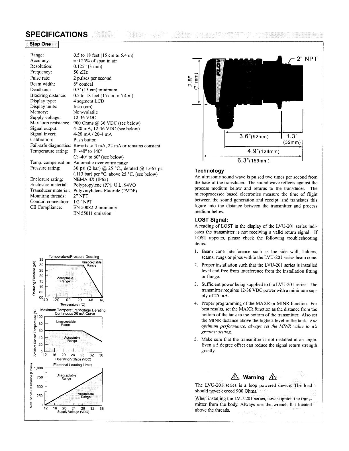
3.6”(Wmm)
n
.
4.9”(124mm)
6.3”(159mm)
I 1.3 ”
(32mm)
cl
cl
Technology
An ultrasonic sound wave is pulsed two times per second from
the base of the transducer. The sound wave reflects against the
process medium below and returns to the transducer. The
microprocessor based electronics measure the time of flight
between the sound generation and receipt, and translates this
figure into the distance between the transmitter and process
medium below.
LOST Signal:
A reading of LOST in the display of the
LVU-201
series indi-
cates the transmitter is not receiving a valid return signal. If
LOST appears, please check the following troubleshooting
items:
1.
Beam cone interference such as the side wall, ladders,
seams, rungs or pipes within the LVU-201 series beam cone.
2.
Proper installation such that the LVU-201 series is installed
from
level and free
interference from the installation fitting
or flange.
Sufficient power being supplied to the LVU-201 series. The
3.
transmitter requires 12-36 VDC power with a minimum sup-
ply of 25
4.
Proper programming of the MAXR or MINR function. For
mA.
best results, set the MAXR function as the distance from the
bottom of the tank to the bottom of the transmitter. Also set
the MTNR distance above the highest level in the tank.
MNR
u1wuy.r
optimum performance,
greatest setting.
5.
Make sure that the transmitter is not installed at an angle.
set the
value to
Even a 5 degree offset can reduce the signal return strength
greatly.
I
For
it:k
16 20 24
Supply Voltage
26 32 36
(WC)
A Warning
A
The LVU-201 series is a loop powered device. The load
should never exceed 900 Ohms.
When installing the LVU-201 series, never tighten the trans-
mitter from the body. Always use the wrench flat located
above the threads.
Page 3

SAFETY PRECAUTIONS
1
Step Two
DEFINITIONS
)
Step
Three
h
About this Manual:
PLEASE READ THE ENTIRE MANUAL PRIOR TO
INSTALLING OR USING THIS PRODUCT. This manual
includes information on all versions of the continuous ultrasonic
level transmitter from Omega; model LVU-201. Please refer to the
part number located on the sensor label to verify the exact model
which you have purchased.
User’s Responsibility for Safety:
h
Omega manufactures a wide range of liquid level sensors and tech-
nologies. While each of these technologies are designed to operate
in a wide variety of applications, it is the user ’s responsibility to
select a technology that is appropriate for the application, install it
properly, perform tests of the installed system, and maintain all
components. The failure to do so could result in property damage
or
serious injury.
h
Proper Installation and Handling:
Because this is an electrically operated device, only
trained staff should install and/or repair this product. Use a proper
sealant with all installations. Never overtighten the transmitter
within the fitting. Always check for leaks prior to system start-up.
A
Wiring and Electrical:
A supply voltage of 12-36 VDC is used to power the LVU-201
series transmitter. The sensor systems should never exceed a max-
imum of 36 VDC for the LVU-20 I series.
sensor should bc
national, state, and local codes.
$
Temperature and Pressure:
The
LVU-201 series is designed for use in application temperatures
from -40
to 30 psi
Material Compatibility:
d
The continuous ultrasonic level transmitter, LVU-201 series, is
made of two materials. The enclosure is of Polypropylene (PP) and
the transducer is made of Polyvinylidene Fluoride (PVDF). Make
sure that the model which you have selected is chemically compat-
ible with the application liquids.
liquid-resistant when installed properly, it is not designed to be
immersed.
mally come into contact with fluid.
1
Flammable, Explosive and Hazardous Applications:
DO NOT USE THE LVU-201 SERIES TRANSMITTER IN
CLASSIFIED HAZARDOUS LOCATIONS.
ti
Make a Fail-Safe System:
Design a fail-safe system that accommodates the possibility of
transmitter or power failure. In critical applications, Omega rec-
ommends the use of redundant backup systems and alarms in addi-
tion to the primary system.
“C
@
performed
(-40 “F) to 60
25 “C, derated
It
should be mounted in such a way that it does not nor-
in accordance with all applicable
“C
(140 “F), and for use at pressures up
@
1.667 psi per
While
Electrical wiring of the
“C
above 25 “C.
the transmitter housing is
properly-
mA
EC4:
The 4
201 series. The EC4 is the distance
from the bottom of the LVU-201 to
mA
the 4
measured in either inches or cen-
timeters on the display. The EC4 set-
ting is typically greater than the
EC20 setting and is equal to the dis-
tance from the bottom of the trans-
ducer to the bottom of the tank.
EC20: The 20
LVU-201 series. The EC20 is the
distance from the bottom of the
LVU-201 to the 20
This setting is measured in either
inches or centimeters on the display. The EC20 setting is typically the
distance from the bottom of the transducer to the highest level in the
tank.
SAFlISAFZISAF3:
SAF_
the
When
becomes LOST. When
mA
remain constant if the signal becomes LOST.
FAST/SLOW:
is the typical setting for the LVU-201 series to operate. [SLOW] is
designed to help dampen out effects caused by severe turbulence. In
the [FAST] mode, the LVU-201 series will
es per second and update every second. In the [SLOW] mode, the
LVU-20
onds. When used with [SAF
is 30 seconds for [FAST] mode and 2.5 minutes for [SLOW] mode.
ALIN:
show the return signal strength in
mechanical alignment of the LVU-201 series and/or signal attenua-
tion. Typical readings range between 2 and 60
alignment, first energize the unit and receive a valid return signal.
Then select the
display is maximized.
ON/OFF:
turned [OFF] when alignment is completed.
This mode will not automatically default back
to [LEVL].
MAXR:
maximum range. The MAXR sets
mum tank height and will filter out
all
(value):
maximum distance is 216.0 inches.
The MAXR value is typically set
equal to the EC4 setting.
MINR:
[MINR] or the minimum range. The
MINR value is the
to the transducer face where no sig-
nal will be generated. The MINR sets the minimum distance between
the liquid and the transducer.
(value):
The
settings to determine a fail-safe mode for the current signal.
[SAFl] is set, the current will increase to 22
if the signal becomes LOST. When
1
series will average signal returns over the preceding 10 sec-
Indicates that the unit is in the Alignment mode. Display will
Actual
Used as an indication for
returns greater than this value.
Actual MAXR setting. The
Used as an indication for
Actual MINR setting. The minimum distance is 6.0 inches,
MINR
value is typically set equal to the EC20 setting.
Fail-Safe setting for the LVU-201 series. Use
[SAF2]
is set, the current will decrease to 4
Setting for echo averaging on the LVU-201. [FAST]
l/2/3], the time for the current to default
dB’s.
ALIN mode and adjust the LVU-201 series until the
setting
for
ALM mode. The
[
deadband
closest
setting for the
set point. This setting is
mA
setting for the
mA
mA
if the signal
the
[SAF3]
average
Used
is set,
ALIN
current will
2 signal respons-
as an indicator for
dB’s.
For optimum
mode must be
set point.
LVU-
Page 4

PROGRAMMING
Step Four
EC4:
I.
Hold [MENU] key until EC4 appears in display.
2. Release [MENU] key and wait until a value appears. This value is
the
current measured level value.
3. If this is
4. From here, use the
5. Press the [SET] key to enter this value as the new EC4 set point.
EC20:
I.
Hold [MENU] key until EC20 appears in display.
2. Release [MENU] key and wait until a value appears. This value is
3. If this is acceptable, press [SET] to lock the value as the new EC20
4. From here, use the
5. Press the [SET] key to enter this value as the new EC20 set point.
SAFlISAFZISAF3:
I.
Hold [MENU] key until
2. Release [MENU] key and hold [SET] key to toggle between SAF 1,
3. When desired setting is reached, release [SET] key. The last dis-
acceptable, press [SET] to lock
set point. If not, press either the
setting for the EC4 will appear.
]
keys to raise or lower the value to the
]
or [t
[s
desired value.
the current measured level value.
set point. If not, press either the
setting for the EC4 will appear.
desired value.
play.
SAF2 and SAF3.
played setting will bc locked into memory. To change, start again
at step 1.
]
keys to raise or lower the value to the
]
or [t
[e
SAFl, SAF2 or SAF3 appears in the dis-
the
value as the new
]
keys once and the old
]
or [t
[S
]
keys once and the old
]
or [t
[S
EC4
WIRING
Step Five
LVU-201
the
in order to operate.
1. Wiring
2.
Wiring to a Two-Wire Loop Indicator:
3.
Wiring to a PLC:
1
requires 12-36 VDC power with at least 25
to a Omega Continuous Controller:
mA
supply
FAST/SLOW:
1.
Hold [MENU]
2. Relcasc [MENU] key and hold [SET] key to toggle between FAST
and SLOW.
3. When desired setting is reached, release [SET] key. The last dis-
played setting will be locked into memory. To change, start again
at step 1.
ALIN:
1. Hold [MENU] key until
2. Continue to hold [MENU] key until OFF appears in the display.
3. Release [MENU] key and hold [SET] key to toggle from OFF to
ON.
4. Release [SET] key. the LVU-20 1 is now in
5. To exit
MAXR:
I. Hold [MENU] key until MAXR appears in
2. Continue to hold [MENU] key until a value appears in the display.
This value is the current MAXR setting.
3. If this is acceptable, press [SET] to lock the value as the MAXR
setting. If not, use the
the desired setting.
4. Press the [SET] key to enter this value as the new MAXR setting.
MINR:
I.
Hold [MENU] key until MINR appears in the display.
2. Continue to hold [MENU] key until a value appears in the display.
This value is the current
3. If this is acceptable, press [SET] to lock the value as the
ting. If not, use the
desired value.
4. Press the [SET] key to enter this value as the new MINR setting.
key until FAST or SLOW appears in the display.
ALIN
appears in the display.
ALIN
ALIN
mode, repeat steps 1-4 changing from ON to OFF.
the
raise
]
keys to
]
or [t
[s
MINR
setting.
]
keys to raise or lower the value to the
]
or [t
[s
or lower
mode.
display.
the
MINR
value to
set-
Hints:
Icvcl.
Current must change with
tion below, as level increases, the current output will increase and as
the level decreases, the current output will decrease. If the output of
the LVU-201 series is always reading 4
values for the LVU-201 series.
changes
Example: For the illustra-
in
mA
or 20
mA,
check the input
El
20
4
mA
mA-
-3
EC4
I
Page 5

INSTALLATION
Step Six
1
INSTALLATION
Step Seven
Mounting the LVU-20
1
series is critical to the successful
operation
the transmitter. Avoid the following parameters:
Avo i d
ln t e ti e r ence
fr o m s ide o f
t ank
i----l
Minimum Range
(MINR) Setting
The MINR setting is typically the dis-
tance from the bottom of the transducer to
the highest level in the tank.
installing the LVU-201 series in a flange
or any device which recesses the bottom
of the transmitter, the minimum setting
for the MINR is the distance
from
tom of the transmitter to the end of the
flange. Never set MINR to less than 6.0
set the
MINR value to
Alwyvs
inches.
greatest setting.
Maximum Application Range
The maximum range of LVU-20lseries is
I8
feet at 1 IO
dB.
less than ideal conditions, a number of factors can reduce the overall
quality of signal return and shorten the accurate range of the
determine
tcr. To
the
signal return formula against the echo attenuation graph below.
low
the maximum application range of the product, fol-
Echo Attenuation Graph
ALIGNMENT
m
tr ansduce r = 40 ”
AL I N
s i b l e
= 26dB
an ica l
a li gn m en t o f un it
d i sp l ayed
MAXIMUM RANGE
AL I N
BatD=40”
When
the bot-
Under
transmit-
va l ue
of
it?
Factory Settings:
The LVU-201 series is preset at the factory. When powering up the
transmitter the first time, the factory settings will be active. If at any
time in you need to return to these settings, remove power from the
LVU-201 series and wait IO seconds. Press the [Set] and [Menu] but-
tons simultaneously while powering up the transmitter.
EC4
EC20 8” (20.3 cm)
216” (548.4
c m )
OFF
MAXR
OFF
WA
Changing Display Units:
The LVU-201 series comes preset to measure in inches. To change the
unit to display centimeters, remove
wait IO seconds. Press
]
and [Set] simultaneously while powering
[S
power to the LVU-201
series
up the transmitter. The LVU-201 series will now read in centimeters.
To return to inches, remove power and wait 10 seconds. Press [t
[Set] simultaneously while powering up the transmitter.
Depth Radius Radius
(Feet) (Inches) (cm)
1
2
3
4
5
6
7
8
9
IO
11
12
13
14
15
16
17
18
1.2 3.1
2.1
2.9 7.3
3.7 9.5
4.6
5.4
6.2
7.1
7.9
8.8
9.6
10.4
11.3
12.1
13.0
13.8
14.6
15.5
5.2
11.6
13.7
15.9
18.0
20.1
22.3
24.4
26.5
28.7
30.8
32.9
35.1
37.2
39.3
I
I
I
f _
C -- G
I
\
\
I
R ad ius
I
I
I
I
- _ - z
1
k
w -- w -
and
]
and
00
40
80
120
DISTANCE FROM FACE OF TRANSDUCER (inches)
160 200
240
 Loading...