

Page 1
M-2051 1/22/02 1:03 PM Page 2
W h e re Do I Find Everything I Need for
P rocess Measurement and Control?
OMEGA…Of Course!
Shop online at www.omega.com
T E M P E R AT U R E
Thermocouple, RTD & Thermistor Probes, Connectors, Panels & Assemblies
Wire: Thermocouple, RTD & Thermistor
Calibrators & Ice Point References
Recorders, Controllers & Process Monitors
Infrared Pyrometers
PRESSURE, STRAIN AND FORCE
Transducers & Strain Gages
Load Cells & Pressure Gages
Displacement Transducers
Instrumentation & Accessories
User’s Guide
Shop online at
F L O W / L E V E L
Rotameters, Gas Mass Flowmeters & Flow Computers
Air Velocity Indicators
Turbine/Paddlewheel Systems
Totalizers & Batch Controllers
p H / C O N D U C T I V I T Y
pH Electrodes, Testers & Accessories
Benchtop/Laboratory Meters
Controllers, Calibrators, Simulators & Pumps
Industrial pH & Conductivity Equipment
D ATA ACQUISITION
Data Acquisition & Engineering Software
Communications-Based Acquisition Systems
Plug-in Cards for Apple, IBM & Compatibles
Datalogging Systems
Recorders, Printers & Plotters
H E AT E R S
Heating Cable
Cartridge & Strip Heaters
Immersion & Band Heaters
Flexible Heaters
Laboratory Heaters
E N V I R O N M E N TA L
MONITORING AND CONTROL
Metering & Control Instrumentation
R e f r a c t o m e t e r s
Pumps & Tubing
Air, Soil & Water Monitors
Industrial Water & Wastewater Treatment
pH, Conductivity & Dissolved Oxygen Instruments
M2051/0102
www.omega.com
e-mail: info@omega.com
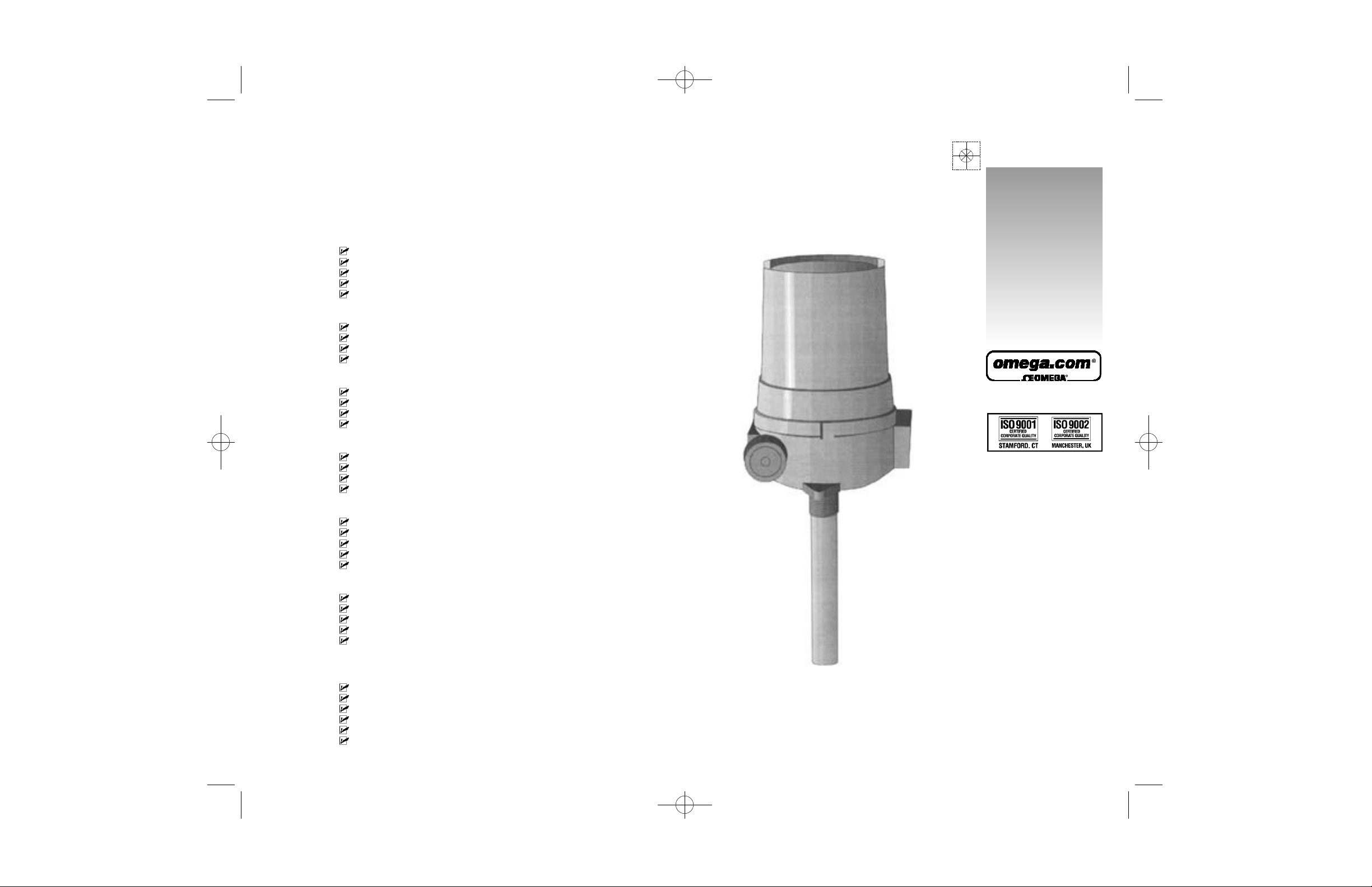
LVU-800, & LV U - 1 1 0 0
Ultrasonic Level System
Page 2
M-2051 1/22/02 1:03 PM Page 4
OMEGAnet®Online Service Internet e-mail
w w w.omega.com i n f o @ o m e g a . c o m
Servicing North America:
USA: One Omega Drive, Box 4047
ISO 9001 Certified
Canada: 976 Bergar
Stamford CT 06907-0047
Tel: (203) 359-1660 FAX: (203) 359-7700
e-mail: info@omega.com
Laval (Quebec) H7L 5A1
Tel: (514) 856-6928 FAX: (514) 856-6886
e-mail: info@omega.ca
For immediate technical or application assistance:
USA and Canada: Sales Service: 1-800-826-6342 / 1-800-TC-OMEGA
Mexico: En Espan˜ol: (001) 203-359-7803 e-mail: espanol@omega.com
Benelux: Postbus 8034, 1180 LA Amstelveen, The Netherlands
Czech Republic: Rude´ arma´dy 1868, 733 01 Karvina´ 8
France: 9, rue Denis Papin, 78190 Trappes
Germany/Austria: Daimlerstrasse 26, D-75392 Deckenpfronn, Germany
United Kingdom: One Omega Drive, River Bend Technology Centre
ISO 9002 Certified
It is the policy of OMEGA to comply with all worldwide safety and EMC/EMI regulations that
apply. OMEGA is constantly pursuing certification of its products to the European New Approach
Directives. OMEGA will add the CE mark to every appropriate device upon certification.
The information contained in this document is believed to be correct, but OMEGA Engineering, Inc. accepts
no liability for any errors it contains, and reserves the right to alter specifications without notice.
WARNING: These products are not designed for use in, and should not be used for, patient-connected applications.
Customer Service: 1-800-622-2378 / 1-800-622-BEST
Engineering Service: 1-800-872-9436 / 1-800-USA-WHEN
TELEX: 996404 EASYLINK: 62968934 CABLE: OMEGA
FAX: (001) 203-359-7807 info@omega.com.mx
Tel: +31 (0)20 3472121 FAX: +31 (0)20 6434643
Toll Free in Benelux: 0800 0993344
e-mail: sales@omegaeng.nl
Tel: +420 (0)69 6311899 FAX: +420 (0)69 6311114
Toll Free: 0800-1-66342 e-mail: czech@omega.com
Tel: +33 (0)130 621 400 FAX: +33 (0)130 699 120
Toll Free in France: 0800-4-06342
e-mail: sales@omega.fr
Tel: +49 (0)7056 9398-0 FAX: +49 (0)7056 9398-29
Toll Free in Germany: 0800 639 7678
e-mail: info@omega.dl
Northbank, Irlam, Manchester
M44 5BD United Kingdom
Tel: +44 (0)161 777 6611 FAX: +44 (0)161 777 6622
Toll Free in United Kingdom: 0800-488-488
e-mail: sales@omega.co.uk
Servicing Europe:
WARRANTY/DISCLAIMER
OMEGA ENGINEERING, INC. warrants this unit to be free of defects in materials and
workmanship for a period of 13 months from date of purchase. OMEGA’s Warranty adds an
additional one (1) month grace period to the normal one (1) year product warranty to cover
handling and shipping time. This ensures that OMEGA’s customers receive maximum
coverage on each product.
If the unit malfunctions, it must be returned to the factory for evaluation. OMEGA’s C u s t o m e r
Service Department will issue an Authorized Return (AR) number immediately upon phone or
written request. Upon examination by O M E G A, if the unit is found to be defective, it will be
repaired or replaced at no charge. O M E G A ’ s WARRANTY does not apply to defects resulting
from any action of the purchaser, including but not limited to mishandling, improper interfacing,
operation outside of design limits, improper repair, or unauthorized modification. This
WARRANTY is VOID if the unit shows evidence of having been tampered with or shows evidence
of having been damaged as a result of excessive corrosion; or current, heat, moisture or vibration; improper specification; misapplication; misuse or other operating conditions outside of
O M E G A ’ s control. Components which wear are not warranted, including but not limited to
contact points, fuses, and triacs.
OMEGA is pleased to offer suggestions on the use of its various products. However,
OMEGA neither assumes responsibility for any omissions or errors nor assumes liability
for any damages that result from the use of its products in accordance with information
provided by OMEGA, either verbal or written. OMEGA warrants only that the parts
®
®
®
manufactured by it will be as specified and free of defects. OMEGA MAKES NO OTHER
WARRANTIES OR REPRESENTATIONS OF ANY KIND WHATSOEVER, EXPRESS OR
IMPLIED, EXCEPT THAT OF TITLE, AND ALL IMPLIED WARRANTIES INCLUDING ANY
WARRANTY OF MERCHANTABILITY AND FITNESS FOR A PARTICULAR PURPOSE ARE
HEREBY DISCLAIMED. LIMITATION OF LIABILITY: The remedies of purchaser set forth
herein are exclusive, and the total liability of OMEGA with respect to this order, whether
based on contract, warranty, negligence, indemnification, strict liability or otherwise, shall
not exceed the purchase price of the component upon which liability is based. In no event
shall OMEGA be liable for consequential, incidental or special damages.
CONDITIONS: Equipment sold by OMEGA is not intended to be used, nor shall it be used: (1) as
a “Basic Component” under 10 CFR 21 (NRC), used in or with any nuclear installation or activity;
or (2) in medical applications or used on humans. Should any Product(s) be used in or with any
nuclear installation or activity, medical application, used on humans, or misused in any way,
OMEGA assumes no responsibility as set forth in our basic WARRANTY/DISCLAIMER language,
and, additionally, purchaser will indemnify OMEGA and hold OMEGA harmless from any liability
or damage whatsoever arising out of the use of the Product(s) in such a manner.
RETURN REQUESTS/INQUIRIES
Direct all warranty and repair requests/inquiries to the OMEGA Customer Service Department.
BEFORE RETURNING ANY PRODUCT(S) TO OMEGA, PURCHASER MUST OBTAIN AN
AUTHORIZED RETURN (AR) NUMBER FROM OMEGA’S CUSTOMER SERVICE DEPARTMENT
(IN ORDER TO AVOID PROCESSING DELAYS). The assigned AR number should then be
marked on the outside of the return package and on any correspondence.
The purchaser is responsible for shipping charges, freight, insurance and proper packaging to
prevent breakage in transit.
FOR WARRANTY RETURNS, please have
the following information available BEFORE
contacting OMEGA:
1. Purchase Order number under which
the product was PURCHASED,
2. Model and serial number of the product
under warranty, and
3. Repair instructions and/or specific
problems relative to the product.
OMEGA’s policy is to make running changes, not model changes, whenever an improvement is possible.
This affords our customers the latest in technology and engineering.
OMEGA is a registered trademark of OMEGA ENGINEERING, INC.
© Copyright 2001 OMEGA ENGINEERING, INC. All rights reserved. This document may not be copied, photocopied,
reproduced, translated, or reduced to any electronic medium or machine-readable form, in whole or in part, without
the prior written consent of OMEGA ENGINEERING, INC.
FOR NON-WARRANTY REPAIRS,
consult
OMEGA for current repair charges. Have the
following information available BEFORE
contacting OMEGA:
1. Purchase Order number to cover the
COST of the repair,
2. Model and serial number of the
product, and
3. Repair instructions and/or specific problems
relative to the product.
Page 3
M-2051 1/22/02 1:03 PM Page 6
5
System Configuration Document
ZERO : inches from sensor face
SPAN : inches from zero
ALARM 1 : inches from sensor face (K1-RELAY)
ALARM 2 : inches from sensor face (K2-RELAY)
ALARM 3 : inches from sensor face
ALARM 4 : inches from sensor face
LINEAR CHARACTERIZATION - DISPLAY
LOW VALUE :
HIGH VALUE:
NOTE
Unpacking Instructions
Remove the Packing List and verify that you have received all
equipment, including the following (quantities in parenthesis):
LVU-800 & LVU-1100 Ultrasonic Level Measurement System (1)
Operator’s Manual (1)
If you have any questions about the shipment, please call OMEGA
Customer Service Department.
When you receive the shipment, inspect the container and equipment for
signs of damage. Note any evidence of rough handling in transit.
Immediately report any damage to the shipping agent.
NOTE
The carrier will not honor damage claims unless all
shipping material is saved for inspection. After
examining and removing contents, save packing
material and carton in the event reshipment is
necessary.
If you select “SLFC” mode
1 = Automatic fill control
2 = Automatic empty control
Alarm #1 relay will act as a auto fill /
auto empty control relay
i14
Page 4

M-2051 1/22/02 1:03 PM Page 8
T A B L EO F
C O N T E N T S
SECTION 1 SYSTEM DESCRIPTION
SECTION 2 INSTALLATION
SECTION 3 LVU-1100 PROGRAMMING DESCRIPTION
SECTION 4 LVU-800 PROGRAMMING DESCRIPTION
LVU-800 & LVU-1100 Series
Ultrasonic Level Systems
1.1 System Description 1
1.2 Principles of Operation 1
2.1 Control Unit Installation 2
2.2 Sensor Installation 2
2.3 Wiring Diagram (Fig. 1) 3
2.4 Calibration Diagram (Fig 2) 4
AND PROMPT LIST
3.1 General 6
3.2 Calibration Procedure 6
AND PROMPT LIST
4.1 General 9
4.2 Calibration Procedure 9
4.3 Dimensional Drawings 12
5
SITE LOCATION ID:
JOB:
UNIT SERIAL NUMBER DATE:
PROGRAMMABLE PARAMETERS, PROGRAMMED BY:
HEIGHT MODE: ❑
DISTANCE MODE: ❑
ANALOG OFFSET: ❑ Y ❑ 4-20 mA ❑ 2-10 V
System Configuration Document
SECTION 5 SYSTEM CONFIGURATION DOCUMENT
5.1 General 13
ii 13
❑ N ❑ 0-20 mA ❑ 0-10 V
DISPLAY MODE: ❑ 0 ❑ 1 ❑ 2
LOST ECHO MODE: ❑ 0 ❑ 1 ❑ 2
❑ STD. ALARM
❑ AUTOMATIC FILL
❑ AUTOMATIC EMPTY
Page 5

M-2051 1/22/02 1:03 PM Page 10
4
LVU - 800 Programming
Description and Prompt List
1
System Description
SECTION I SYSTEM DESCRIPTION
1.1 GENERAL DESCRIPTION
The OMEGA Model, LVU-800 / LVU-1100 Series Liquid Level
Systems are state-of-the-art level measurement instruments.
Based on the latest ultrasonic technologies, the LVU-800 / LVU- 1 1 0 0
Series provide an efficient, reliable and cost effective means of level
control.
The LVU-800 / LVU-1100 Series consist of 2 major components: a
non-contacting ultrasonic sensor and a compact, remote electronic
control.
The LVU-800 / LVU-1100 Series sensor is available in a variety of sizes
and materials to suite virtually any application. Standard
mounting configurations include 3/4” and 2” NPT fittings. Sensor
materials of construction include 316 SS, kynar or teflon.
*3/4” NPT Teflon® Sensor Length 2” (50.8mm) STD
DIMENSIONAL DRAWINGS
LVU-1100 Series 4-20 MA Transmitter continuous output with
two programmable alarm relay with auto fill /
auto empty mode.
LVU-800 Series Two programmable alarm relay with independent
alarm, auto fill / auto empty mode.
1.2 PRINCIPLES OF OPERATION
In operation, the electronics generates an electronic signal that is
converted by the sensor (mounted on top of the vessel) to a burst of
ultrasonic pulses. These pulses are transmitted through the air towards
the liquid surface. As the pulses reach the liquid surface, they are reflected
back to the sensor. These received echoes are converted back to an
electronic signal, which is then sent to a microprocessor. The
microprocessor uses the return signals to calculate the it takes for the
pulses to travel to the liquid surface and back. This “Time of Flight” is
directly proportional to the distance of the liquid surface from the
sensor. The microprocessor then compares these calculated values with
user programmed system parameters to provide the required control
output.
112
Page 6

M-2051 1/22/02 1:03 PM Page 12
2
System Description
SECTION II INSTALLATION
2.1 CONTROL UNIT INSTALLATION
1. Open control unit enclosure and remove the printed circuit board.
2 . Replace printed circuit board, and route power and control
wiring to the enclosure. Observe all applicable local electrical
codes and wiring procedures.
3 . Connect power and control wiring to the control unit as shown in
the wiring diagram (see figure 1).
4 . Be sure that all wiring is carefully dressed to prevent pinching
between the housing and the cover.
2.2 Sensor Installation
The sensor is mounted on the top of the vessel with the sensor facing
downward. A clear path, free of any obstructions, must be provided
between the sensor and the liquid surface. Due to the narrow sensor
beam pattern, vertical-axis positioning of the sensor is important. The
sensor must be installed so as to maintain perpendicularity to the liquid
surface.
1. For sensors provided with an NPT threaded fitting, drill a
suitable hole in the vessel top and tap for the correct NPT
thread. In thin walled vessels, or vessels constructed of
material not suitable for tapping, weld or braze a bushing to
accept the sensor.
2. Screw the sensor into the threaded fitting, being careful not to
cross thread the sensor. When possible, the use of a pipe
compound or sealing tape is recommended.
AVOIDOVER TIGHTENING!
3. For flange mounted sensors, simply bolt the sensor / flange
assembly to the proper mating flange connection.
4. Route the sensor cable to the electronic control unit and connect per the
Wiring diagram (see fig 1). IF ROUTING THE SENSOR CABLE
THROUGH CONDUIT, A DEDICATED CONDUIT SHOULD BE
UTILIZED. AVOID ROUTING THE SENSOR CABLE IN CLOSE
PROXIMITY TO ANY SOURCEOF ALTERNATING CURRENT OR
RFI.
2 11
LVU - 800 Programming
Description and Prompt List
PROMPT DEFINITION DESCRIPTION
S L _ S SELECT SPAN PROGRAMS THE SYSTEMS
S L L E SELECT LOST PROGRAM ONE OF THE THREE
ANALOG VARIABLES ON SIGNAL ECHO LOSS
OUTPUT 0 = OUTPUT GOES TO 4 mA
1. 1-3 OPERATION MODE: AUTOMATIC FILL / AUTO FILL WITH
ALTERNATE PUMP CONTROL
2. 2-4 OPERATION MODE: AUTOMATIC FILL / AUTO FILL WITH
ALTERNATE PUMP CONTROL
PROGRAM PARAMETER:
SLAH
SLAL
3. 5 OPERATION MODE BOTH PUMPS ARE OFF WHEN LEVEL IS
BELOW “SLAL”. AS THE LEVEL INCREASES
TO “SLA3” PUMP #1 / OR PUMP #2 STARTS,
PUMP STAYS ON UNTIL THE LEVEL
DECREASES BELOW “SLAL” THEN STOPS.
IF THE LEVEL CONTINUES TO INCREASE UP
TO “SLAH” PUMP #2 / OR PUMP #1 COMES ON
AND DECREASES BELOW “SLAL”.
PROGRAM PARAMETER:
S L A H
S L A L
S L A 3
ANALOG OUTPUT SPAN
MEASURED IN INCHES FROM THE
ZERO POINT.
1 = OUTPUT HOLDS LAST
G O O D V A L U E
2 = OUTPUT GOES TO 20 mA
4
Page 7

M-2051 1/22/02 1:03 PM Page 14
LVU-800 Programming
4
Description and Prompt List
PROMPT DEFINITION DESCRIPTION
S L A 1 SELECT ALARM PROGRAM ALARM RELAY #1 TRIP
S L A 2 SELECT ALARM PROGRAM ALARM RELAY # 2 AS
S L A H SELECT ALARM (THIS PROMPT ONLY AVAILABLE
S L A L SELECT ALARM (THIS PROMPT ONLY AVAILABLE
S L A 3 PUMP START PROGRAM PUMP START LEVEL POINT
RELAY 1 AS DESIRED, MEASURED IN INCHES
FROM FACE OF PROBE
EXAMPLE: 18” = ‘0 1 8.0’
(THIS PROMPT NOT AVAILABLE IF “S L F C” IS SET TO 1 OR 2)
RELAY 2 AS DESCRIBED ABOVE
HIGH LEVEL IF “S L F C” IS SET TO 1 OR 5)
PROGRAM THE HIGHEST LEVEL
POINT AS MEASURE IN INCHES FROM
THE SENSOR FACE FOR ALL 2-5
OPERATIONS.
LOW LEVEL IF “S L F C” IS SET TO 1 OR 5)
PROGRAM THE LOW LEVEL POINT
AS MEASURE IN INCHES FROM
THE SENSOR FACE FOR ALL 2-5
OPERATIONS.
LEVEL AS MEASURED IN INCHES FROM
THE SENSOR FACE. THIS PROMPT IS
ONLY AVAILABLE IF SLFC IS SET TO 5
2.3 WIRING DIAGRAM
Installation
2
S L D H SELECT THE HEIGHT MODE PROVIDES AN
DISTANCE ANALOG OUTPUT PROPOTTIONAL
MEASUREMENT TO THE LIQUID LEVEL, AND THE
MODES DISTANCE MODE PROVIDES AN
INVERSE OUTPUT.
H = HEIGHT MEASUREMENT
d = DISTANCE MEASUREMENT
S L O S SELECT ALLOWS FOR AN ANALOG OFFSET
ANALOG REFERENCED TO 0mA OR 4 mA
EXAMPLE: 0-20 mA VERSUS 4-20 mA
OR 0-10 Vdc OR 2-10 Vdc
1 = 4-20 mA dc
0 = 0-20 mA dc
S L _ 0 SELECT ZERO PROGRAMS THE SYSTEM ZERO
POINT FOR THE ANALOG OUTPUT
AS MEASURED IN INCHES FROM
THE FACE OF THE SENSOR
NOTE
THE SYSTEM ZERO SETTING IS THE POINT CLOSET TO
THE SENSOR FACE. THE ZERO POINT WILL BE 20 mA
IN HEIGHT MODE AND 4mA IN DISTANCE MODE.
310
Page 8

M-2051 1/22/02 1:03 PM Page 16
2
Installation
2.4 CALIBRATION DIAGRAM
4
LVU-800 Programming
Description and Prompt List
SECTION IV LVU-800 PROGRAMMING
DESCRIPTION AND PROMPT LIST
4.1 GENERAL
The LVU-800 Series is calibrated via push-button entry switches
(Program & Increment) and an onboard digital display, which provides
the necessary programming prompts. All data entered during the
calibration procedure is stored in a non volatile memory to prevent loss
of data in the event of a power failure.
During the calibration procedure you may refer to the programming
Prompt List and the calibration diagram in this manual.
NOTE
DURING THE CALIBRATION PROCEDURE, IF NO
BUTTONS ARE PUSHED FOR MORE THAN 60 SECONDS,
THE SYSTEM WILL AUTOMATICALLY RETURN TO THE
OPERATING MODE-SAVING THOSE PARAMETERS
ALREADY ENTERED.
4.2 CALBRATION PROCEDURE
Unscrew the control unit cover and simultaneously depress and hold the
Program and Increment buttons. After approximately three (3) seconds,
the onboard programming display will issue the prompt “COdE”.
Release both buttons and press the Program button.
Follow chart below for programming setup.
PROMPT DEFINITION DESCRIPTION
S L F C SELECT RELAY DEFINES THE OPERATIONAL MODE
FUNCTIONS ALARM RELAY #1, AS FOLLOWS
4 9
0=STD (INDEPENDENT ALARMS)
1=AUTOMATIC FILL CONTROLS
2=AUTOMATIC EMPTY CONTROL
3=LEAD/LAG WITH ALTERNATE
PUMP AND AUTOMATIC FILL
PUMP CONTROL
4=LEAD/LAG WITH ALTERNATE
PUMP AND AUTOMATIC EMPTY
PUMP CONTROL
5=ALTERNATE PUMP CONTROL
WITH THREE SETTING, AUTO
EMPTY MODE
Page 9

M-2051 1/22/02 1:03 PM Page 18
LVU-800 Programming
3
Description and Prompt List
3.2 CALIBRATION PROCEDURE Con’t
S L _ S SELECT SPAN PROGRAMS THE SYSTEM ANALOG
S L L E SELECT LOST PROGRAM ONE OF THE THREE
ANALOG VARIABLES ON SIGNAL ECHO LOSS
OUTPUT 0 = OUTPUT GOES TO 4 mA
OUTPUT SPAN MEASURED IN INCHES
FROM THE ZERO POINT.
1 = OUTPUT HOLDS LAST GOODVALUE
2 = OUTPUT GOES TO 20 mA
2.5 SPECIFICATIONS
Range: 1 - 12 feet
Repeatability: 1/8 inch typical
Accuracy: Analog output - 1/4% of full scale
Temperature Compensation:
Input Power: 115 V ac, 50/60 Hz, 24 Vdc
Output Signal: 4-20 ma dc (isolated)
Alarm Setpoints: Two independent
Installation
1 - 30 feet (“30 ft” option)
Automatic over full range of
sensor operating temperature
or 230 V ac optional
or 0-10 Vdc
programmable 10A SPOT
relays increments of 0.1”
over entire span
2
Temperature Range: Sensor - 20°F to + 180° F
Electronics - 10°F to + 170°F
Sensor Pressure Rating: 250 psig - 316 SS
100 psig - Teflon, Kynar, CPVC
Sensor Construction: CPCV 316 SS, Kynar or T e f l o n
Electronics Enclosures: NEMA7 explosion-proof
Class I, Division 1 & 2 Groups
B, C&D
Class II, Division 1 & 2 Groups
E, F&G
Class III, NEMA 3, 4, 7, & 9
Mountings:
3
/4” NPT: Range up to 12 Ft
2” NPT: Range up to 30 Ft
58
Page 10

M-2051 1/22/02 1:03 PM Page 20
3
LVU-1100 Programming
Description and Prompt List
SECTION III LVU-1100 PROGRAMMING
DESCRIPTION AND PROMPT LIST
3.1 GENERAL
The LVU-1100 Series is calibrated via push-button entry switches
(Program & Increment) and an onboard digital display, which provides
the necessary programming prompts. All data entered during the
calibration procedure is stored in a non volatile memory to prevent loss
of data in the event of a power failure.
During the calibration procedure you may refer to the programming
Prompt List and the calibration diagram in this manual.
NOTE
DURING THE CALIBRATION PROCEDURE, IF NO BUTTONS ARE
PUSHED FOR MORE THAN 6 0 SECONDS,THE SYSTEM WILL
AUTOMATICALLY RETURN TO THE OPERATING MODE-SAVING
THOSE PARAMETERS ALREADY ENTERED.
LVU-1100 Programming
Description and Prompt List
3.2 CALIBRATION PROCEDURE Con’t
PROMPT DEFINITION DESCRIPTION
S L A 2 SELECT ALARM PROGRAM ALARM RELAY # 2 AS
RELAY 2 AS DESCRIBED ON PAGE 6.
S L A H SELECT ALARM (THIS PROMPT ONLY AVAILABLE
S L A L SELECT ALARM (THIS PROMPT IS ONLY AVAILABLE
S L A 3 PUMP START PROGRAM PUMP START LEVEL POINT
HIGH LEVEL IF “S L F C” IS SET TO 1 OR 5)
PROGRAM THE HIGHEST LEVEL POINT
AS MEASURE IN INCHES FROM
THE SENSOR FACE FOR ALL 2-5
OPERATIONS.
LOW LEVEL IF “S L F C” IS SET TO 1 OR 5)
PROGRAM THE LOW LEVEL POINT
AS MEASURE IN INCHES FROM
THE SENSOR FACE FOR ALL 2-5
OPERATION.
LEVEL AS MEASURED IN INCHES FROM
THE SENSOR FACE. THIS PROMPT IS
ONLY AVAILABLE IF SLFC IS SET TO 5
3
3.2 CALBRATION PROCEDURE
Unscrew the control unit cover and simultaneously depress and hold the
Program and Increment buttons. After approximately three (3) seconds,
the onboard programming display will issue the prompt “COdE”.
Release both buttons and press the Program button.
Follow chart below for programming setup.
PROMPT DEFINITION DESCRIPTION
S L F C SELECT RELAY DEFINES THE OPERATIONAL MODE
FUNCTIONS ALARM RELAY #1, AS FOLLOWS
0=STD (INDEPENDENT ALARMS)
1=AUTOMATIC FILL CONTROLS
2=AUTOMATIC EMPTY CONTROL
3=LEAD/LAG WITH ALTERNATE
PUMP AND AUTOMATIC FILL
PUMP CONTROL
4=LEAD/LAG WITH ALTERNATE
PUMP AND AUTOMATIC EMPTY
PUMP CONTROL
5=ALTERNATE PUMP CONTROL
WITH THREE SETTING, AUTO
EMPTY MODE.
S L A 1 SELECT ALARM PROGRAM ALARM RELAY #1 TRIP
RELAY 1 AS DESIRED, MEASURED IN INCHES
FROM FACE OF PROBE
EXAMPLE: 18” = ‘0 1 8.0’
(THIS PROMPT NOT AVAILABLE IF “S L F C” IS SET TO 1 OR 2)
6 7
S L D H SELECT THE HEIGHT MODE PROVIDES AN
DISTANCE ANALOG OUTPUT PROPOTTIONAL
MEASUREMENT TO THE LIQUID LEVEL, AND THE
MODES DISTANCE MODE PROVIDES AN
INVERSE OUTPUT.
H = HEIGHT MEASUREMENT
d = DISTANCE MEASUREMENT
S L O S SELECT ALLOWS FOR AN ANALOG OFFSET
ANALOG REFERENCED TO 0mA OR 4 mA
EXAMPLE: 0-20 mA VERSUS 4-20 mA
OR 0-10 Vdc OR 2-10 Vdc
1 = 4-20 mA dc
0 = 0-20 mA dc
S L _ 0 SELECT ZERO PROGRAMS THE SYSTEM ZERO
POINT FOR THE ANALOG OUTPUT
AS MEASURED IN INCHES FROM
THE FACE OF THE SENSOR
NOTE
THE SYSTEM ZERO SETTING IS THE POINT CLOSET TO
THE SENSOR FACE. THE ZERO POINT WILL BE 20 mA
IN HEIGHT MODE AND 4mA IN DISTANCE MODE.
 Loading...