

Page 1
LVU-
1000
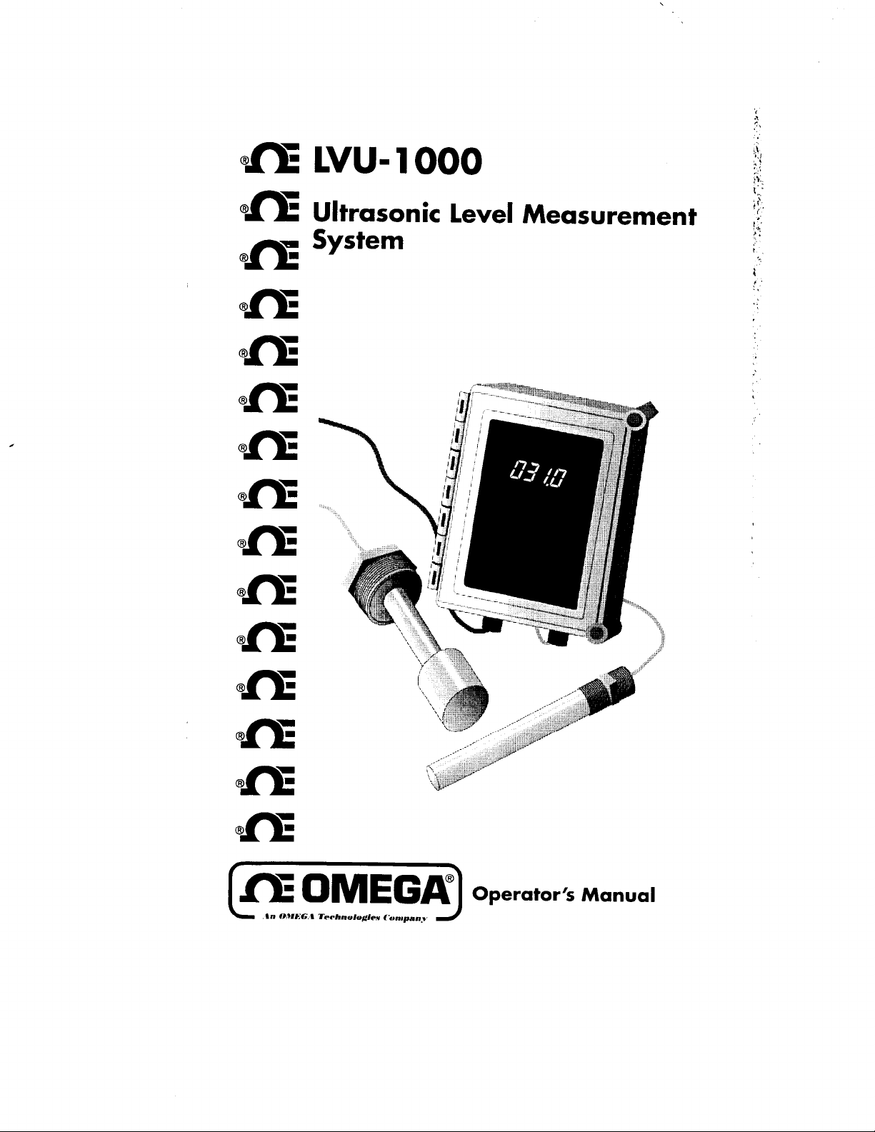
Ultrasonic Level Measurement
System
Operator’s Manual
Page 2
Unpacking instructions
L
A.
Trr...l.#h OMIYEA
Servicing USA and Canada: Call OMEGA Toll Free
One Omega Drive, Box 4047
Stamford, CT 06907-0047
Telephone: (203) 359-1660
FAX: (203) 359-7700
Engineering Service: l-800-872-9436
TELEX: 996404 EASYLINK: 62968934 CABLE: OMEGA
USA
Sales Service: 1-800-826-6342
Customer Service: I-800-622-2378
J
(ir,..y
Canada
ar
976 Ber
(
Lava1
Telephone: (514) 856-6928
FAX: (514) 856-6886
/
l-800.TC-OMEGA“’
I-ROO-622-BEST”
/
I-800.USA-WHEN”’
/
H7L
8
5A1
twbec)
Remove the Packing List and verify that you have received ail equipment,
including the following (quantities in parentheses):
LVU-1000 Ultrasonic Level Measurement System (1)
Operator’s Manual (1)
If you have any questions about the shipment, please call the OMEGA Customer
Service Department.
the
When you receive the shipment, inspect
container and equipment for
damage. Note any evidence of rough handling in transit. Immediately report any
damage to the shipping agent.
Servicing Europe: United Kingdom Sales and Distribution Center
25 Swannington Road, Broughton Astley, Leicestershire
Telephone: 44 (1455) 285520
The OMEGA Complete Measurement and
Control Handbooks
ti
Temperature
v
Pressure, Strain
r/
Flow and Level
pH and Conductivity
w
&
Force
LE9
6TU,
England
FAX: 44 (1455) 283912
& Encyclopedias
r/
Data Acquisition Systems
V
Electric Heaters
V
Environmental Monitoring
and Control
The carrier will not honor damage claims unless all shipping
material is saved for inspection. After examining and removing
contents, save packing material and carton in the event reship-
ment is necessary.
Call for Your FREE Handbook Request Form Today: (203)
359-RUSH
Page 3

LVU-
1000
Series
System Description
Chapter 1
Chapter 2
Chapter 3
Chapter 4
Chapter 5
Chapter 6
Chapter 7
System Description
Principles of Operation
Installation
Control Unit Installation
Sensor Installation
Wiring Diagram
Sensor Diagram
System Features and Operating Modes
General
Standard Features
Optional Features
System Calibration
General ........................................ .
Calibration Procedure
Calibration Diagram
Specifications
Linear Characterization Rrief Description
Analog Output Calibration VERIFICATION Procedure
Programming Prompt list
System Configuration Document
....................... .
-
-
Figure 2
........................................... .
....................................
.................... .
...................
..............................
...................................
Figure 1
............................
.............................
.......
....................................
.................................. .
.................... .
............................
-
Figure 3
.....................
...........
.............. .
............
.
... .
Page
..l-
.2-l
3-1
.3-l
.3-l
.3-2
.3-3
.4-l
..4- 1
.4-l
..4- 1
..5- 1
.
5-1
.
.
5-1
.
.
5-4
.
.
5-5
5-6
.5-B
. .
.6-l
.
.7- 1
1
System Description
The OMEGA Model LVU-1000 series liquid level system is a
of-the-art level measurement instrument. Based on the latest
ultrasonic technologies, the LVU-1000 series provides an efficient,
reliable and cost effective means of level control.
The LVU-1000 series consists of 2 major components: a
contacting ultrasonic sensor and a compact, remote electronic
control.
The LVU-1000 series is available in a variety of sizes and materials to
suit virtually any application. Standard mounting configurations
%”
include a
to meet user specifications. Sensor materials of construction include
CPVC, 316 SS, Kynar or Teflon.
and 2 ” NPT fittings. Flange mounting is also available
Chapter 8
ii
Dimensional Drawings
-
Dimensional Drawings
Figure 4
....................
......................
.8- 1
.8-l
Page 4
.::::
System Description
s
Principles of Operation
.:::.
..::r.
.::F
..::;.
.::F
.::..
:$
7
‘:
Principles of Operation
In
operation, the electronics generates an electronic signal which is
converted by the sensor (mounted on
ultrasonic pulses. These pulses are transmitted through the air
towards the liquid surface. As the pulses reach the liquid surface,
they are reflected back to the sensor. These received echoes are
converted back to an electronic signal, which is then sent to the
microprocessor. The microprocessor uses the return signals to
calculate the time it takes for the pulses to travel to the liquid surface
and back. This “Time of Flight ” is directly proportional to the
distance of the liquid surface from the sensor. The microprocessor
then compares these calculated values with user programmed
system parameters to provide the required control outputs.
1-2
Page 5
P ri nc ip les of Operation
..&
$7
&
,:p
,:.>
4r
,$
Con tr o l
Senso r
Un it I ns ta ll a ti on
1.
2.
3.
4.
Ins ta ll a ti on
The sensor is mounted on the top of the vessel with the sensor facing
downward. A clear path, free of any obstructions, must be provided
between the sensor and the liquid surface. Due to the narrow sensor
beam pattern, vertical-axis positioning of the sensor is important.
The sensor must be installed so as to maintain perpendicularity to
the liquid surface.
1.
2.
Open control unit enclosure and remove the printed circuit board.
Replace printed circuit board, and route power and control wiring
to the enclosure. Observe all applicable local electrical codes and
wiring procedures.
Connect power and control wiring to the control unit as shown in
the wiring diagram (see figure 1).
Be sure that all wiring is carefully dressed to prevent pinching
between the housing and the cover.
For sensors provided with an NPT threaded fitting, drill a suitable
hole in the vessel top and tap for the correct NPT thread. In thin
walled vessels, or vessels constructed of material not suitable for
tapping, weld or braze a bushing to accept the
Screw the sensor into the threaded fitting, being careful not to
cross thread the sensor. When possible, the use of a pipe
compound or sealing tape is recommended.
tightening!
2-2
For flange mounted sensors, simply bolt the sensor/flange
3 .
assembly to the proper mating flange connection.
Route the sensor cable to the electronic control unit and connect
4.
per the Wiring diagram (see figure 1).
IF ROUTING THE SENSOR CABLE THROUGH CONDUIT,
A DEDICATED CONDUIT SHOULD BE UTILIZED. AVOID
ROUTING THE SENSOR CABLE IN CLOSE PROXIMITY TO
ANY SOURCE OF ALTERNATING CURRENT OR RFI.
Page 6

9
..$f
Installation
Q
q
kogrammlng
Leme”,
I -
Vogramming
Switches
Dlsplay
-a-
- -
Enter
Temperature
rTransmttler/RCV
r
-
-
-
Compcnsahon
-
Sensifhr~AdJwlmetW
I
Compensallon
Temp.
-
El
Ad/uslmsnl
Anabg
‘OPTIONAL
Lad
Echo Relay
mmm lsssl m
LllZGnd
-- d -I\-
Power
OVIC 1
NOCNC NOCNC NOCNC NOCN C
Alan-n
wwnl
lnpul
1
\
Relay
Oulpuls
Alum
lOAmp
_
3A&m 2
SPDT
-1
analog
4Alam,
/
Serrscf
noI
Do
adpst
Oubul
Do not attempt to remove a threaded sensor from the vessel
with the cable attached to the control unit, otherwise cable
may be damaged.
W-0)
r
I
L
3-2
Figure
1 Wiring Diagram
Figure 2 Sensor Diagram
Page 7

System Features and
General
The LVU-1000 series is an extremely versatile instrument. It ’s many
standard programmable features and available options can be
utilized to perform a wide variety of control functions. In many
cases, a single LVU-1000 can accomplish control functions which
would otherwise only be possible through the use of multiple
instruments or expensive computer based systems.
Standard
1.
2.
3.
4.
5.
6.
7.
Operating
Modes
Features
Automatic temperature compensation compensates for sound
velocity errors (due to temperature variations) over the entire
sensor temperature range.
Simple 2 button programming.
Four programmable Alarm point relays.
User selectable Height or Distance operating mode.
fully
isolated analog output with programmable output offset.
Three “Lost Echo” condition modes (user selectable).
Internal 4-digit display provides programming prompts, system
heartbeat, and “Lost Echo” feedback.
Enhanced noise rejection algorithm ignores spurious signals and
8.
other noise sources such as 60 cycle and RFI.
Optional Features
1.
External (front covered mounted) 4 digit display for local
indication.
2.3.Optional “Lost Echo” alarm relay, in place of alarm
Customized response times and output damping to meet special
application requirements. Call factory for application assistance.
Page 8

System Features and Operating Modes
General
System Calibration
The LVU-1000 series is calibrated via push-button entry switches
(Enter and Increment) and an
provides the necessary programming prompts. All data entered
during the calibration procedure is stored in a nonvolatile memory
to prevent loss of data in the event of a power failure.
During the calibration procedure, you may wish to refer to the
Programming Prompt List and the Calibration Diagram found
elsewhere within this manual.
During the Calibration procedure, if no button is pressed
for more than 60 seconds, the system will automatically
return to the Operating Mode, saving only those parameter
values already entered.
onboard
4-2
Upon completion of the Calibration procedure, the Analog Output
may be verified by following the Calibration Verification Procedure
(see step 11).
Calibration Procedure
1.
Open control unit enclosures and simultaneously depress and
hold the Enter and Increment buttons. After approximately 3
seconds, the
“COdE”.
Enter button once to bypass this prompt (this prompt is for factory
use only, and is not user accessible).
onboard
The
2.
once and the
operotion, or “d” for Distance Mode of operation, depending on
the previously programmed mode. Pressing the Increment button
now will toggle the display between “H” and “d”. The Height
Mode of operation will provide an analog output proportional to
the liquid level, while the Distance Mode will provide an inverse
onboard
Release both Enter and Increment and then press the
display will issue the prompt
display will read either “H” for Height Mode of
programming display will issue the prompt
Page 9

/’
Jr
System Calibration
output (refer to the Calibration Diagram). With the desired
operating mode displayed, press Enter to select that mode.
3. The next prompt to be displayed will be “SLOS” for “select analog
offset”. The Analog offset determines if the analog output signal is
referenced to zero or some offset
a current output, or O-l 0 V dc vs. 2-l 0 V dc for voltage output).
Press Enter to display the previously entered selection (either 0 or
1). Pressing Increment now will toggle the display between 0 and
II
1.
Entering “1
“0” disables the
displayed, press the Enter button to store the selection.
4. The display
At this time the analog output is driven to its proper state
and may be verified, see step 11.
The Zero Point is the point at which the level will be closest to the
sensor (refer to the Calibration Diagram). The minimum Zero
Point is normally 12 ” from the sensor face.
In certain applications, the LVU-
provide a closer Zero Point. Consult factory.
Press Enter now, and the display will indicate the previously
programmed Zero value, with the “hundreds” digit flashing. Press
Increment to increment the flashing digit to its desired value. With
the desired value displayed for the “hundreds” place digit, press
Enter to store the value. The next digit
be flashing. Repeat the above steps for the “Tens”, “Inches” and
will invoke the
Analog Offset. With the desired selection
will
now issue the
value
(O-20 ma vs. 4-20 ma for
Analog Offset, while entering a
“SL-0”
prompt, for “select zero”.
1000
may be configured to
(
the ‘Tens” place) will now
“Tenths of inches” places to obtain the desired Zero point as
measured in inches from the sensor face.
Upon entry of the Zero Point, the display will issue the prompt
5.
“SL_?
for “select Span”.
At this time the analog output may be verified, see step 1 1.
The Span is the measurement range in inches as measured from
the Zero Point. Press Enter now and the display will indicate the
current Span value, with the hundreds place digit flashing.
Proceed as in step 4 to enter the desired Span in inches from the
Zero Point.
6. After entering the desired Span, the system will issue the prompt
“SLdF”
for “select display function”. This parameter will define the
4
operation of the operational
provided). Press Enter now, and the on board programming
display will indicate a digit of 0 or 1, depending on the
previously entered selection. The Display Function Modes are as
follows:
digit panel-mounted display (if
Mode 0: Display reads distance of target from sensor
in inches.
Mode 1: Display indicates value of linear range
programmable by the user. See the calibration
Linear Characterization Display Scaling for details on
programming this mode.
Pressing Increment will toggle the programming
display through the above Display Function Modes. Press
Enter to store the desired Mode.
If you have selected display mode 1 at the “SLdF”
prompt, then you have chosen Custom Display Scaling and
the unit proceeds to step 6a in the following manner,
otherwise the unit proceeds to step 7.
5-2
Page 10

System Calibration
Specifications
Range:
Repeatability:
Accuracy:
Temperature
Compensation:
Input Power:
Output Signal:
Controls:
Display:
Alarm
Setpoink:
Temperahrre Range:
Sensor Pressure
Rating:
Construction:
Cable:
E&onics
Enclosures:
Mountings:
1-12 feet
1 to 30 feet
KY
Analog output-x% of
&VU-1000)
&VU-1010)
typical
Automatic over
temperature
115 V oc,
4-20
Programmable zero and span, height and
50/60
ma dc (isolated)
mode
Four digit (optional)
Four 1 OA SPDT relays. Programmable
increments of
(optional)
Sensor -22°F to
Electronics -10°F
-
250 psig
psig)
316 S.S.
20”
NEMA-4X (standard)
%“:
2”: (Range up
316 SS (Plastic models limited to 150
St&&x
up
(Range up to 12
Figure 3 Calibration Diagram
Page 11

System Calibration
linear Characterization Brief Description:
The LVU-1000 series allows the user to enter a four digit minimum
arbitrary value, a four digit maximum arbitrary value, and a decimal
position. The display output is
two
values across the previously programmed Span (Calibration
-
Procedure
step 5). The display always increases or decreases in a
manner that is directly proportional to the analog output, which is
based on the selection of Height or Distance mode.
6a.
The unit issues the “SLLO” prompt for “select
display value. Pressing Enter causes the display to advance and
show the previously programmed Low value.
then linearly scaled between these
LOw”
minimum
The unit checks that the
Hlgh value. If this error is detected the unit returns to step
6a
and the user must re-enter valid
6c.
The unit issues the
Pressing Enter causes the display to advance and show the
previously programmed Decimal Place. The display
digit from 0 to 3 indicating the desired precision or the number of
decimal digits to be displayed. Pressing Increment will step the
display through the above decimal place values. Once the desired
decimal place is displayed, press Enter to select that value.
LOw value is not greater than the
“SLdP”
prompt for “Select Decimal Place”.
Ignore the decimal point on the
and it has no meaning in this mode. Proceed as in the
Calibration Procedurestep 4 to enter the desired arbitrary
low point.
6b.
The unit next issues the “SLHI” prompt for “Select High, maximum
display value”. Pressing Enter causes the display to advance and
show the previously programmed Hlgh value.
Again, ignore the decimal point on the
Proceed as the Calibration Procedure-step 4 to enter the
desired arbitrary Hlgh point.
onboard
onboard
display-it is fixed
disploy.
Now the unit proceeds with step 7 of this Calibration Procedure.
will
The next prompt issue
7.
Press Enter to enable the flashing digits as in step 4 and enter the
desired Alarm Point
The
the sensor face, regardless of Operating Mode.
Repeat step 7 for Alarm Points 2, 3, and 4 (prompts
8.
and
After
9.
prompt “SLLE” for “Select Lost Echo Mode”. The last Echo mode
selection determines the stotus of the analog output should a loss
of valid return echo occur. Press the Enter button now and the
display will
Pressing Increment will toggle the programming display through
the Lost Echo Modes listed below. Press Enter to select the desired
Lost Echo Mode: The Lost Echo Modes are as follows:
Points are always programmed in inches from
Alarm
SLA4).
Alarm Point 4 is entered, the display will then issue the
indicate
be
in inches from the sensor face.
the current Lost Echo Mode (either 0,
5-6
Page 12

8
Programming Prompt list
.::::
#
..:..
. .. .
.::::
.:::.
$2
.:::
Jr
,g
Mode 0: Analog output goes to minimum output.
Mode 1: Analog output holds last valid reading.
Mode 2: Analog output goes to maximum output.
10. Upon entry of the desired Lost Echo Mode, the system will return
to the operating mode. The programming displays will display the
system “heartbeat”, a pulsing
complete.
“0”
character. Calibration is
Analog output calibration verification procedure
11. To verify the
digital current meter or voltmeter to the
(refer to Wiring Diagram, page 3-3). Access the Calibration
Mode by simultaneously pressing ond holding the Enter and
Increment buttons, until the
two buttons, then repeatedly press and release the Enter button
until the
Analog output is correct per the selected Operating Mode
(Distance or Height Mode, with or without Analog Offset. Also
refer to the Calibration Diagram). Continue to repeatedly press
and release Enter,
Verify that the Analog output is correct per the selected Operating
Mode. The system will automatically return to the normal
operating mode after 60 seconds, displaying heartbeat.
The analog output level can be adjusted through the analog
adjust multi-turn potentiometer shown in figure 1. With the
analog
adjust this potentiometer until your digital multimeter is
precisely at 20
requires no
“SL-0”
output at its maximum
adiustment.
output of the LVU- 1000 series, connect a
analog
Analog
Output terminals
“COdE” prompt appears. Release the
(Select Zero) prompt is issued. Verify that the
until
the
“SL_S” (Select Span) prompt appears.
mA
(20
or 10 V dc),
mA or
IeveI
10
V dc. The analog minimum value
Prompt
SLdH
SLOS
SL_O
SL_S
SLdF
SLLO
SLHI
SLdP
SLAl
SLA2
SLA3
SLA4
Definition
Select Distance or
Height
Mode
Select Analog
Offset
Select Zero
Select Span
Select Display
Function
Select Low or
Minimum Value
Select High or
Maximum Value
Select Decimal
Points
Select Alarm
Select Alarm 2
Select Alarm 3
Select Alarm 4
1
Description
The Height mode provides an analog output
proportional to the liquid level (4-20 ma or
dc), and the Distance mode provides an inverse
(20-4 ma or
output
Height Mode or “d” for Distance Mode.
Allows for an analog output referenced to Zero or
some Offset reference (4-20 ma vs O-20 ma for a
current output, or a 2-10 V dc vs O-10 V dc for a
voltage output). Select 0 to disable the Offset;
select 1 to invoke the Offset.
Programs the system Zero point as measured from
the sensor face in inches. The system Zero is the
point at which the level is closest to the sensor
face.
Programs the system Span as measured in inches
from the system Zero point.
Defines the operational mode of the optional 4
digit display. Mode “0” displays target distance
from sensor in inches. Mode “1” displays user
defined Linear scaled output.
Linear Characterization sub-mode that defines the
minimum value that the display should indicate.
Linear Characterization sub-mode that defines the
maximum value that the display should indicate.
Linear Characterization sub-mode that defines the
decimal digits to be displayed.
Programs Alarm Point 1 as measured in inches
from the sensor face.
Programs Alarm Point 2 as measured in inches
from the sensor face.
Programs Alarm Point 3 as measured in inches
from the sensor face.
Programs Alarm Point 4 as measured in inches
from the sensor face.
5-8
Page 13

9
.
4f
Programming Prompt List
,f
.:v
c.
System Configuration
Document
SLLE
Select Lost Echo
Mode
Programs the analog output condition in the event
of a loss of a valid return echo for more than 8
seconds.
Mode 0 Output goes to minimum.
Mode 1 Output holds last reading.
Mode 2 Output goes to maximum.
In a lost echo condition, the 4 digit display and the
onboard
display will display
“-LE-“.
SITE/LOCATION ID:
JOB:
UNIT SERIAL NUMBER:
PROGRAMMABLE PARAMETERS,
__
:
_
?
0
0
O N
??
0
Y
0
0
HEIGHT MODE:
DISTANCE MODE:
ANALOGOFFSET:
DISPLAY MODE:
LOST ECHO MODE:
ZERO :
SPAN
ALARM1
ALARM 2
:
:
PROGRAMMED BY:
0
4-20
(
0
O-20mA
(
01
01
0
0
02
inches from sensor face
inches from zero
inches from sensor face
inches
6-2
ALARM3
ALARM4 :
LINEAR CHARACTERIZATION -DISPLAY
VALUE:
LO
HI VALUE:
DECIMAL
:
PLACE:
0
0
0
1
inches from sensor face
inches from sensor face
0
2
Page 14

8-l
Dimensional Drawings
FIBERUlllf ENCLOSURE
NW-IX
+
WARRANTY
OMEGA warrants this unit to be free of defects in materials and workmanship and to
satisfactory
adds an additional one (1) month grace period to the normal one (1) year product
warranty
receive maximum coverage on each product. If the unit should malfunction, it must be
returned to the factory for evaluation. OMEGA’s Customer Service Department will issue an
Authorized Return (AR) number immediately upon phone or written request. Upon
examination by OMEGA, if the unit is found to be defective it will be repaired or replaced at
no charge. However, this WARRANTY is VOID if the unit shows evidence of having been
tampered with or shows evidence of being damaged as a result of excessive corrosion; or
current, heat, moisture or vibration; improper specification; misapplication; misuse or other
operating conditions outside of OMEGA’s control. Components which wear or which are
damaged by misuse are not warranted. These include contact points, fuses, and
OMEGA is glad to
theless, OMEGA only
service for a period of 13 months from date of purchase. OMEGA Warrantv
to cover
handling and shipping time. This ensures that OMEGA’s customers
offer suggestions on the use of its various products. Never-
warrants that
the
parts manufactured by it will be as
specified and free of defects.
OMEGA MAKES NO OTHER WARRANTIES OR REPRESENTATIONS OF ANY KIND
WHATSOEVER, EXPRESSED OR IMPLIED, EXCEPT THAT OF TITLE AND
IMPLIED WARRANTIES INCLUDING ANY WARRANTY
AND FITNESS FOR A PARTICULAR PURPOSE ARE HEREBY DISCLAIMED.
LIMITATION OF LIABILITY: The remedies of purchaser set forth herein are
exclusive and the total liability of OMEGA with respect to this order, whether
based on contract, warranty, negligence, indemnification, strict liability or
otherwise, shall not exceed the purchase price of the component upon which
liability is based. In no event shall OMEGA be liable for consequential, incidental
or special damages.
Every precaution for accuracy has been taken in the preparation of this manual; however,
OMEGA ENGINEERING, INC. neither assumes responsibility for any omissions or errors
that may appear nor assumes liability for any damages that result from the use of the
products in accordance with the information contained in the manual.
SPECIAL CONDITION: Should this equipment be used in or with any nuclear installation or
activity, purchaser will indemnify OMEGA and hold OMEGA harmless from any liability or
damage whatsoever arising out of the use of the equipment in such a manner.
RETURN REQUESTS
Direct all warranty and repair requests/inquiries to the OMEGA ENGINEERING Customer
Service Department. BEFORE RETURNING ANY PRODUCT(S) TO OMEGA, PURCHASER
MUST OBTAIN AN AUTHORIZED RETURN (AR) NUMBER FROM OMEGA’S CUSTOMER
SERVICE DEPARTMENT (IN ORDER TO AVOID PROCESSING DELAYS). The assigned AR
number should then be marked on the outside of the return package and on any
correspondence.
FOR
WARRANTY
FOR
the following information available
BEFORE contacting OMEGA:
1. P.O. number under which the product
was PURCHASED,
2. Model and serial number of the product
under warranty, and
3. Repair instructions and/or specific
problems relative to the product.
OMEGA’s policy is to make running changes, not model changes, whenever an
improvement is possible. This affords our customers the latest in technology and
engineering.
OMEGA
0
may not be
medium or machine-readable form, in whole or in part, without prior written consent of
OMEGA ENGINEERING, INC.
IS
a registered trademark of OMEGA ENGINEERING. INC.
Copyright 1995 OMEGA ENGINEERING, INC. All rights reserved. This documentation
RETURNS, please have
copled. photocopied, reproduced, translated, or reduced to any electronic
NON-WARRANTY
CALIBRATION,
repair/calibration charges. Have the
following information available BEFORE
contacting OMEGA:
1. P.O. number to cover the COST of the
repair/calibration,
2. Model and serial number of product, and
3. Repair instructions and/or specific
problems relative to the product.
 Loading...