

Page 1
Where Do I Find Everything I Need for
Process Measurement and Control?
OMEGA…Of Course!
TEMPERATURE
䡺⻬
Thermocouple, RTD & Thermistor Probes,
Connectors, Panels & Assemblies
䡺⻬
Wire: Thermocouple, RTD & Thermistor
䡺⻬
Calibrators & Ice Point References
䡺⻬
Recorders, Controllers & Process Monitors
䡺⻬
Infrared Pyrometers
PRESSURE, STRAIN AND FORCE
䡺⻬
Transducers & Strain Gauges
䡺⻬
Load Cells & Pressure Gauges
䡺⻬
Displacement Transducers
䡺⻬
Instrumentation & Accessories
FLOW/LEVEL
䡺⻬
Rotameters, Gas Mass Flowmeters & Flow Computers
䡺⻬
Air Velocity Indicators
䡺⻬
Turbine/Paddlewheel Systems
䡺⻬
Totalizers & Batch Controllers
pH/CONDUCTIVITY
䡺⻬
pH Electrodes, Testers & Accessories
䡺⻬
Benchtop/Laboratory Meters
䡺⻬
Controllers, Calibrators, Simulators & Pumps
䡺⻬
Industrial pH & Conductivity Equipment
DATA ACQUISITION
䡺⻬
Data Acquisition & Engineering Software
䡺⻬
Communications-Based Acquisition Systems
䡺⻬
Plug-in Cards for Apple, IBM & Compatibles
䡺⻬
Datalogging Systems
䡺⻬
Recorders, Printers & Plotters
HEATERS
䡺⻬
Heating Cable
䡺⻬
Cartridge & Strip Heaters
䡺⻬
Immersion & Band Heaters
䡺⻬
Flexible Heaters
䡺⻬
Laboratory Heaters
ENVIRONMENTAL
MONITORING AND CONTROL
䡺⻬
Metering & Control Instrumentation
䡺⻬
Refractometers
䡺⻬
Pumps & Tubing
䡺⻬
Air, Soil & Water Monitors
䡺⻬
Industrial Water & Wastewater Treatment
䡺⻬
pH, Conductivity & Dissolved Oxygen Instruments
M-3939 / 0203
WARRANTY/DISCLAIMER
OMEGA ENGINEERING, INC. warrants this unit to be free of defects in materials and workmanship for a
period of 13 months from date of purchase. OMEGA Warranty adds an additional one (1) month grace
period to the normal one (1) year product warranty to cover handling and shipping time. This ensures
that OMEGA’s customers receive maximum coverage on each product.
If the unit should malfunction, it must be returned to the factory for evaluation. OMEGA’s Customer Service
Department will issue an Authorized Return (AR) number immediately upon phone or written request. Upon
examination by OMEGA, if the unit is found to be defective it will be repaired or replaced at no charge.
OMEGA’s WARRANTY does not apply to defects resulting from any action of the purchaser, including but not
limited to mishandling, improper interfacing, operation outside of design limits, improper repair, or unautho-
rized modification. This WARRANTY is VOID if the unit shows evidence of having been tampered with or
shows evidence of being damaged as a result of excessive corrosion; or current, heat, moisture or vibration;
improper specification; misapplication; misuse or other operating conditions outside of OMEGA’s control.
Components which wear are not warranted, including but not limited to contact points, fuses, and triacs.
OMEGA is pleased to offer suggestions on the use of its various products. However, OMEGA neither
assumes responsibility for any omissions or errors nor assumes liability for any damages that result
from the use of its products in accordance with information provided by OMEGA, either verbal or writ-
ten. OMEGA warrants only that the parts manufactured by it will be as specified and free of defects.
OMEGA MAKES NO OTHER WARRANTIES OR REPRESENTATIONS OF ANY KIND WHATS0EVER,
EXPRESSED OR IMPLIED, EXCEPT THAT OF TITLE, AND ALL IMPLIED WARRANTIES INCLUDING ANY
WARRANTY OF MERCHANTABILITY AND FITNESS FOR A PARTICULAR PURPOSE ARE HEREBY DIS-
CLAIMED. LIMITATION OF LIABILITY: The remedies of purchaser set forth herein are exclusive and the
total liability of OMEGA with respect to this order, whether based on contract, warranty, negligence,
indemnification, strict liability or otherwise, shall not exceed the purchase price of the component
upon which liability is based. In no event shall OMEGA be liable for consequential, incidental or spe-
cial damages.
CONDITIONS: Equipment sold by OMEGA is not intended to be used, nor shall it be used: (1) as a “Basic
Component” under 10 CFR 21 (NRC), used in or with any nuclear installation or activity; or (2) in medical
applications or used on humans. Should any Product(s) be used in or with any nuclear installation or activity,
medical application, used on humans, or misused in any way, OMEGA assumes no responsibility as set forth
in our basic WARRANTY/ DISCLAIMER language, and additionally, purchaser will indemnify OMEGA and
hold OMEGA harmless from any liability or damage whatsoever arising out of the use of the Product(s) in
such a manner.
RETURN REQUESTS / INQUIRIES
Direct all warranty and repair requests/inquiries to the OMEGA Customer Service
Department. BEFORE RETURNING ANY PRODUCT(S) TO OMEGA, PURCHASER MUST
OBTAIN AN AUTHORIZED RETURN (AR) NUMBER FROM OMEGA’S CUSTOMER SERVICE
DEPARTMENT (IN ORDER TO AVOID PROCESSING DELAYS). The assigned AR number
should then be marked on the outside of the return package and on any correspondence.
The purchaser is responsible for shipping charges, freight, insurance and proper packaging
to prevent breakage in transit.
FOR W
ARRANTY RETURNS, please have
the following information available BEFORE
contacting OMEGA:
1. P.O. number under which the product
was PURCHASED,
2. Model and serial number of the product
under warranty, and
3. Repair instructions and/or specific
problems relative to the product.
FOR NON-WARRANTY REPAIRS,
consult
OMEGA for current repair charges. Have
the following information available
BEFORE contacting OMEGA:
1. P.O. number to cover the COST
of the repair,
2. Model and serial number of product, and
3. Repair instructions and/or specific
problems relative to the product.
OMEGA’s policy is to make running changes, not model changes, whenever an improvement is possible.
This affords our customers the latest in technology and engineering.
OMEGA is a registered trademark of OMEGA ENGINEERING, INC.
© Copyright 1996 OMEGA ENGINEERING, INC. All rights reserved. This document may not be copied,
photocopied, reproduced, translated, or reduced to any electronic medium or machine-readable form, in whole or
in part, without prior written consent of OMEGA ENGINEERING, INC.
USA
MADE
IN
Servicing North America:
USA: One Omega Drive, Box 4047
ISO 9001 Certified Stamford, CT 06907-0047
Tel: (203) 359-1660 FAX: (203) 359-7700
e-mail: info@omega.com
Canada: 976 Bergar
Laval (Quebec) H7L 5A1
Tel: (514) 856-6928 FAX: (514) 856-6886
e-mail: canada@omega.com
For immediate technical or application assistance:
USA and Canada: Sales Service: 1-800-826-6342 / 1-800-TC-OMEGA
SM
Customer Service: 1-800-622-2378 / 1-800-622-BEST
SM
Engineering Service: 1-800-872-9436 / 1-800-USA-WHEN
SM
TELEX: 996404 EASYLINK: 62968934 CABLE: OMEGA
Mexico and
Latin America:
Tel: (95) 800-TC-OMEGA
SM
FAX: (95) 203-359-7807
En Espan˜ol: (203) 359-1660 ext: 2203 e-mail: espanol@omega.com
Servicing Europe:
Benelux: Postbus 8034, 1180 LAAmstelveen, The Netherlands
Tel: (31) 20 6418405 FAX: (31) 20 6434643
Toll Free in Benelux: 06 0993344
e-mail: nl@omega.com
Czech Republic: Ostravska 767, 733 01 Karvina
Tel: 42 (69) 6311899 FAX: 42 (69) 6311114
e-mail: czech@omega.com
France: 9, rue Denis Papin, 78190 Trappes
Tel: (33) 130-621-400 FAX: (33) 130-699-120
Toll Free in France: 0800-4-06342
e-mail: france@omega.com
Germany/Austria: Daimlerstrasse 26, D-75392 Deckenpfronn, Germany
Tel: 49 (07056) 3017 FAX: 49 (07056) 8540
Toll Free in Germany: 0130 11 21 66
e-mail: germany@omega.com
United Kingdom: 25 Swannington Road, P.O. Box 7, Omega Drive,
ISO 9002 Certified Broughton Astley, Leicestershire, Irlam, Manchester,
LE9 6TU, England M44 5EX, England
Tel: 44 (1455) 285520 Tel: 44 (161) 777-6611
FAX: 44 (1455) 283912 FAX: 44 (161) 777-6622
Toll Free in England: 0800-488-488
e-mail: uk@omega.com
OMEGAnet
SM
On-Line Service Internet e-mail
http://www.omega.com info@omega.com
It is the policy of OMEGA to comply with all worldwide safety and EMC/EMI regulations that apply. OMEGA is constantly
pursuing certification of its products to the European New Approach Directives. OMEGA will add the CE mark to every
appropriate device upon certification.
The information contained in this document is believed to be correct but OMEGA Engineering, Inc. accepts no liability for any errors it con-
tains, and reserves the right to alter specifications without notice.
WARNING: These products are not designed for use in, and should not be used for, patient connected applications.
http://www.omega.com
e-mail: info@omega.com
®
User’s Guide
LVR-50 Series
High-Temp Vertical Level Transmitter
OMEGA
®
TM
omega.comomega.com
Page 2
Step One
SPECIFICATIONS
Range: 5" to 72" (12.7 cm to 1.8m)
Accuracy: 0.25”over span in water
Specific gravity: 0.75 minimum
Orientation: ± 30° vertical
Supply voltage: LVR-50-PP series: 10 to 30 VDC
LVR-50 series: 10 to 40 VDC
Loop resistance: 600 Ohms @ 24 VDC
Signal output: 4-20 mA, two-wire
Signal invert: 4-20 or 20-4 mA
Calibration: None, fixed span
Process temp.: F: -40° to 300°
C: -40° to 148.9°
Electronic temp.: F: -40° to 160°
C: -40° to 71°
Pressure: 300 psi max.
20.7 bar max.
Enclosure rating: LVR-50-PP series: NEMA 4X (IP65)
LVR-50 series: NEMA 7 (IP65)
Installed height: LVR-50-PP series: 5.2" (13.2 cm)
LVR-50 series: 6.2" (15.7 cm)
Encl. material: LVR-50-PP series: PP, UL94VO
LVR-50 series: Aluminum
Guide/float mat.: 316 ss
Process mount: 2" NPT
Conduit entrance: Single, 1/2" NPT
Classification: LVR-50-PP series: General purpose
LVR-50 series: Explosion proof
Approvals: FM, CSA: Class I, Division I, Groups B,
(LVR-50 series only) C & D; Class II, Groups E, F and G
CE compliance: EN 50082-2 immunity
EN 55011 emission
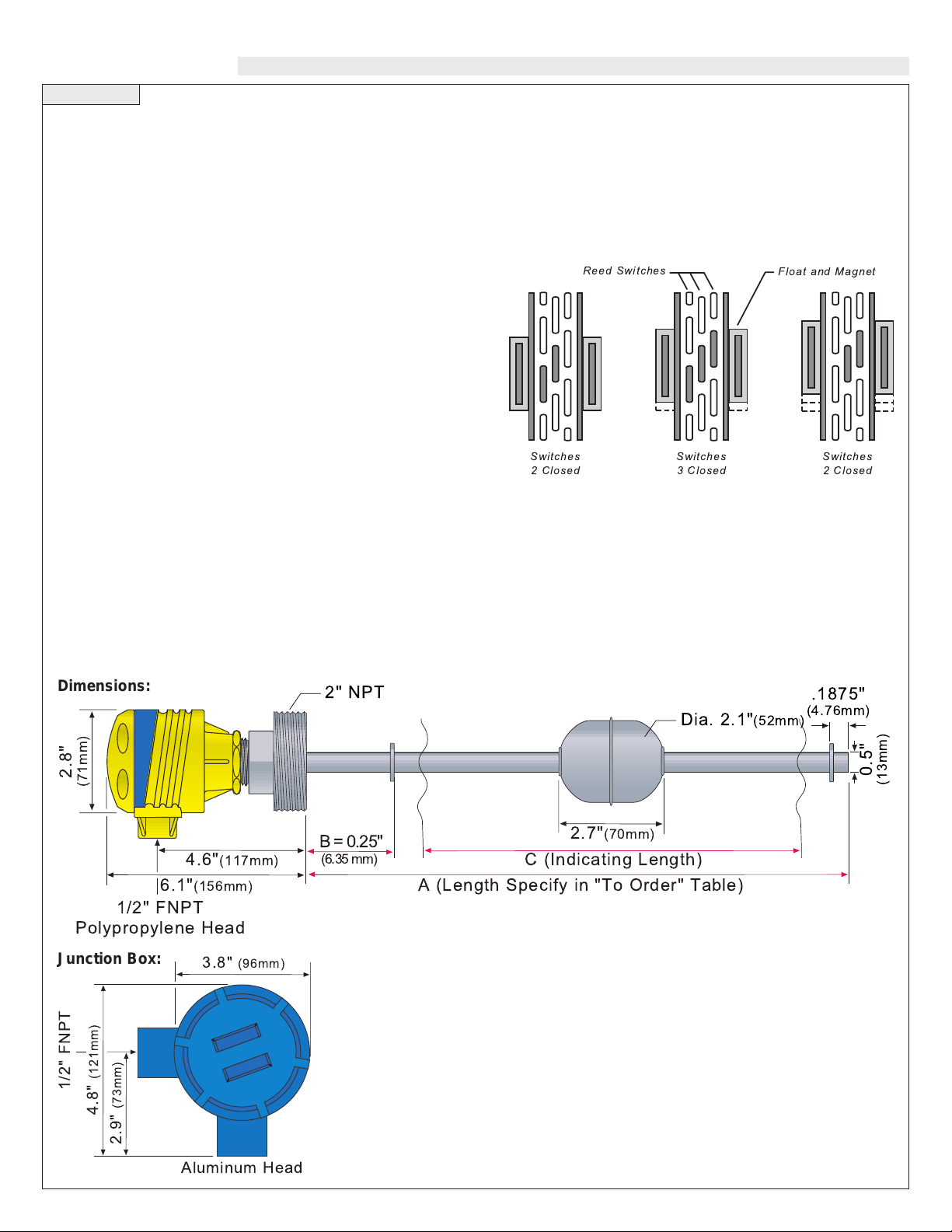
Technology
A single float is attached to a stainless steel rod, which is installed
through the top of the tank. Internal to the rod is a series of reed
switches designed to open and close as the float changes with the liquid level. The internal magnets within the float will open or close the
reed switches in a “2-3-2 at-a-time” sequence, which enables the
transmitter to provide accurate level indication. With every movement of the float, either one additional switch closes or opens.
Dimensions:
Junction Box:
Switches
2 Closed
Reed Switches
Switches
3 Closed
Float and Magnet
Switches
2 Closed
2.8"
(71mm)
4.6"(117mm)
6.1"(156mm)
1/2" FNPT
Polypropylene Head
1/2" FNPT
4.8" (121mm)
3.8" (96mm)
2" NPT
B = 0.25"
(6.35 mm)
Dia. 2.1"(52mm)
2.7"(70mm)
C (Indicating Length)
A (Length Specify in "To Order" Table)
.1875"
(4.76mm)
0.5"
(13mm)
2.9" (73mm)
Aluminum Head
Page 3

Step Two Step Three
SAFETY PRECAUTIONS INSTALLATION
About this Manual:
PLEASE READ THE ENTIRE MANUAL PRIOR TO
INSTALLING OR USING THIS PRODUCT. This manual
includes information on the L VR-50 series Level T ransmitter , models LVR-50-PP series & LVR-50 series. Please refer to the part
number located on the sensor label to verify the exact model which
you have purchased.
User's Responsibility for Safety:
OMEGA manufactures a wide range of liquid level switches and
technologies. While each of these switches is designed to operate
in a wide variety of applications, it is the user's responsibility to
select a switch model that is appropriate for the application, install
it properly, perform tests of the installed system, and maintain all
components. The failure to do so could result in property damage
or serious injury.
Proper Installation and Handling:
Because this is an electrically operated device, only properly
trained staff should install and/or repair this product. Use a proper
sealant with all installations. Never overtighten the sensor within
the fitting, beyond a maximum of 80 inch-pounds torque. Always
check for leaks prior to system start-up. Physical damage sustained
by the product may render it unserviceable.
Material Compatibility:
The wetted portion of the LVR-50 series is available in 316
Stainless Steel. The junction box is made of either Polypropylene
(PP) for the LVR-50-PP series or Aluminum for the LVR-50 series.
Make sure that the switch is compatible with the application liquids. To determine the chemical compatibility between the sensor
and its application liquids, refer to a corrosion guide.
Temperature and Pressure:
The LVR-50-PP series is designed for use in application temperatures up to 300 °F (148.9 °C), and for use at pressures up to 300 psi
(20.7 bar). Temperature and pressure limitations must not be
exceeded.
Wiring and Electrical:
The supply voltage used for the LVR-50-PP series should never
exceed 30 VDC and for the LVR-50 series should never exceed 40
VDC. Electrical wiring of the switch should be performed in
accordance with all applicable national, state, and local codes.
Flammable, Explosive and Hazardous Applications:
The LVR-50-PP series series switch should not be used within
flammable or explosive applications. Only use the LVR-50 series
series in hazardous locations when properly connected to an
approved control device. In hazardous applications, use redundant
measurement and control points, each having a different sensing
technology. Refer to the National Electrical Code (NEC) for all
applicable installation requirements in hazardous locations.
OMEGA’s LVR-50 Series Installation:
OMEGA’s LVR-50 Series is an in tank system. The LVR-50 series
may be installed through the top wall of any tank or flange, using a
standard 2” NPT tank adapter or blind flange. If the top is not available, OMEGA’s side mount bracket, LVM-50, enables LVR-50 series
to be installed directly to the side wall or lip of the tank.
T ank Adapter:
Flange Mounting:
Side Mount Bracket:
Lip of Tank: Side Wall:
Thread Treatment:
Sealing: When threading metal threads into a metal coupling, pipe
sealant or Teflon tape is recommended. When threading a metal sensor into a metal coupling, the installer should use a suitable wrench
and tighten the threads 1-1/2 turns past hand tight.
Page 4

Step Four Step Five
WIRING MAINTENANCE
LVR-50-PP Series: General:
The LVR-50 series level transmitter has no scheduled maintenance
requirement, except to clean off any deposits or scaling from the
switch as necessary. It is the responsibility of the user to determine the
appropriate maintenance schedule, based on the specific characteristics of the application liquid.
Cleaning procedure:
1. Power: Make sure that all power to the transmitter, controller
and/or power supply is completely disconnected.
2. Switch removal: If necessary, make sure that the tank is
drained to a safe level and that the pressure is sufficient for
removal of the LVR-50 series. Carefully, remove the sensor from
the installation.
3. Cleaning the switch: Using a soft bristle brush and mild deter-
gent, carefully wash the switch. Do not use harsh abrasives, which
might damage the surface of the sensor. Do not use incompatible
solvents which may damage the sensor's 316 ss body. Take particular care to remove any scaling from the float body and make
sure that it moves freely.
4. Sensor installation: Follow the appropriate steps of installa-
tion as outlined in the Installation section of this manual.
Troubleshooting:
Verify proper wiring, power supply and loop resistance. If transmitter is not functioning properly, isolate the transmitter from the system
and wire as shown below. Multimeter should read 4 mAwith float at
the bottom and 20 mA with float at the top of the transmitter.
+
-
R
W
B
R5
R1
+
-
DC Power
Supply
18-36 VDC
-
+
123456
SPAN
NULL
+
-
DC Power
Supply
18-36 VDC
-
+
LVR-50 Series:
Warning
For hazardous area applications, use an appropriate intrinsically safe interface device.
Excitation:
The minimum excitation
required for operation of
transmitters with 4-20 mA,
DC signals can be determined
for a given total loop resistance from the graph shown.
(Total loop resistance = sum
of the DC termination resistance plus loop resistance).
For optimum operation,
which is a function of source
voltage (+VA) and total loop
resistance, the source voltage
value used should be above the minimum load line for the related loop
resistance.
+
-
Multimeter
(set for mA)
DC Power
Supply
+
24 VDC
-
COM
mA
-
Choose loop resistance (RL)
to match application
+
Minimum Excitation Required
for Loop Resistance
50
Area of
40
Operation
30
20
10
DC Source Voltage
00
000 200 400 600 800 1000 1200
RL(Ohms) Termination plus
DC Loop Resistance
 Loading...