

Page 1

®
LVCN6200/7200 Series
Capacitive Point Level Detection
Page 2
®
Page 3

Contents
Introduction .................................................4
Models & Dimensions .........................................5
Wiring Diagram ..............................................6
Relay Status Guide ...........................................7
Installation ..................................................8
Calibration .................................................10
Handling ..................................................11
Technical Specifications ......................................12
Trouble Shooting ............................................14
Warranty & Disclaimer ....................................... 15
www.omega.com e-mail: info@omega.com
03
Page 4

Introduction
LVCN 6200 / LVCN 7200
Capacitive Point
Level Detection
The LVCN Series are capacitance switches ideal for High/Low level detection for
liquid, solids, granular materials and pastes. These units can also detect level
without being in contact with the product through a sight glass. Unlike other
capacitance probes, the LVCN6200/7200 can detect conductive, non-conductive or
low dielectric materials with extremely accurate performance without requiring an
external reference or installation in a metal vessel.
Both models can be made with cable or rod rigid stainless steel giving more flexibility
to complex applications.
®
Technology
The sensor operates in a manner that is similar to a simple capacitor. A high
frequency oscillator is located within the tip of the probe. When the tip of the probe
comes in contact with the medium, the frequency of the oscillation reaches a preset
point and the detection circuit signals the switch to change state.
Features
No Moving Parts – RuggedConstruction
Highly customizable:
POM (Polyoxymethylene), PTFEor PVC Sensing Tip
Extended Lengths withboth Rigid 316 rodor Cable
Threaded, Flange orSanitary Process Connections
Available in DC or Universal Power Supplyversions
Almost completely immunefrom build-up, coating mediaaggressive products
Easily applied in a wide range of applications/industries such as: water, oils,
corrosives, solids, powders,grains, conductive as wellas non-conductive medias.
04
Page 5
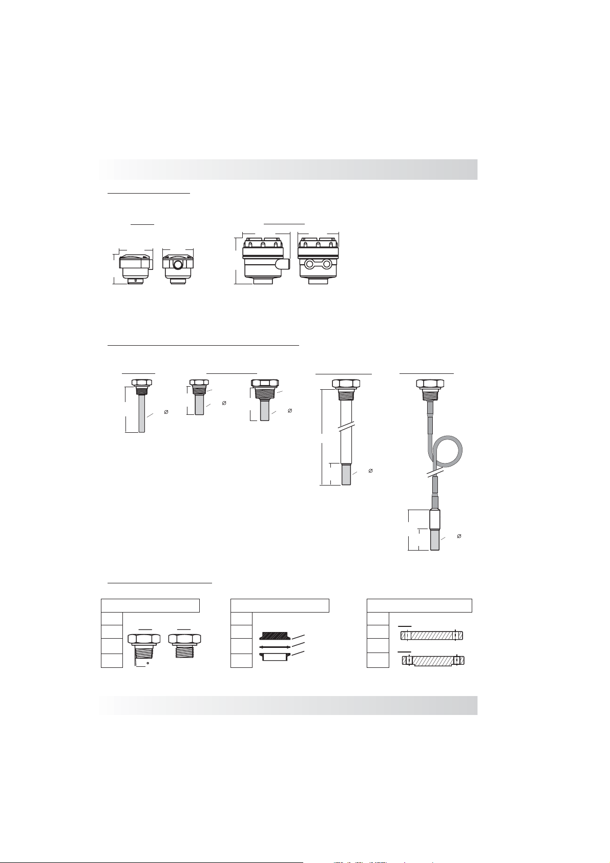
Housing Options
Models and Dimensions
Aluminum
130mm
130mm
76mm
Nylon
89mm
80mm
Mounting Options for LVCN-6200 / 7200
Standard
120mm
15mm
70mm
Standard Sizes
3/4” or 1” NPT
20mm
80mm
1½”NPT
20mm
118mm
Extended Length
L
50mm
Cable Extension
20mm
Process Connections
Threaded Connections
3/4”
1”
NPT
BSP
1½”
2”
1,75
Tri-Clamp Connection
1½”
2”
2½”
3”
www.omega.com e-mail: info@omega.com
TC Connection
Rubber Seal
Process Connection
90mm
50mm
Flange Connections
1”
FF
1½”
2”
RF
2½”
20mm
ANSI 150#
ANSI 300#
05
Page 6

Wiring Diagram
L1 - Power ON (Green)
L2 - Output Status (Red
L3 - Sensor Status (Delay) Yellow
P1 - Sensibility Adjustment
P2 - Time Delay Adjustment
LVCN-7200 Nylon Housing
®
1
- Positive DC
2 - Negative DC
3 - Ground
4-
NO Contact
5-
Common
6-
NC Contact
1
- Power Supply
2-
Power Supply
3 - Ground
4-
Common
5-
NO Contact
6-
Common
7-
NC Contact
8 - Positive DC
9 - Negative DC
Power Supply
24Vdc
Power Supply
Relay Contact
5A-250Vac
L2
3
12
24Vdc
ON
L1
6
5
4
NO
CNC
L3
P1P2
LVCN-6200 Aluminum Housing
Time Delay Adjustment
LVCN-6200
8
-
+
24Vdc
1
2934567
80....260Vac
L1 L2
L3
5
46
3
2
1
0
Sensitivity
H
L
10
7
8
9
10
1
20 sec.
Delay
P2P1
NO
NC
Sensitivity Adjustment
06
Page 7

LVCN-6200
Switch Position
H
Level
Probe covered
NO-NC
4
5
6
7
Relay Status Guide
Green LED
Yellow LED
ON ONON
Red LED
Maximum
fail-safe
L
Minimum
fail-safe
LVCN-7200
Level
Probe uncovered
Probe uncovered
Probe covered
Probe uncovered
SPDT
5
6
4
4
6
ON
5
7
4
6
ON
5
7
7
4
ON
6
5
Green LED
Yellow LED
ON OFF OFF
OFF
ON
OFF
Red LED
OFF
OFF
ON
6
5
4
Probe covered
www.omega.com e-mail: info@omega.com
ON ONON
07
Page 8

Installation
Installation
®
Verify that the location the probe is to be mounted
is clear fromthe stream of product(Fig. 1).
When installing more than one probe in your
process, verify that they are separated by a
minimum distance of500mm (Fig. 1).
Material falling ontothe probe can causedamage
or switching errors. If this is unavoidable, it is
recommended that a protective shield be installed
above the probe to protect it. The shield is also
recommended when the probe is use for a low
level switch orin the outflow ofthe product (Fig. 2).
The tip of the probe should slightly point
downward ( when possible) so that if thereare any
excess of product it will easily slide from the probe
(Fig. 2).
When installing from the top of the tank confirm
that the tip of the probe has cleared the side of the
vessel at least500mm (Fig. 3).
Fig. 2
Shield
500mm
Fig. 3
500mm
Fig. 1
500mm
Fig. 4
When installing the sensor directly to the tank
make sure that the rod extends beyond the inner
wall of the tank, by as much as possible, so that
internal build up or other debris does not interfere
with the sensor's performance (Fig. 2 correct Fig.
4 incorrect).
08
Page 9

Installation
For probes with cable extensions, installation
should be from the top of the tank. It is also
recommended that for these probes the process
shouldn't have any agitation as this can cause
fluctuating readings or damage to the probe
(Fig. 5).
The LVCN with rigid rod is recommended for
applications that have turbulence or vortices
throughout use (Fig.6).
Ensure that the conduit is facing downward to
avoid water fromentering the housing (Fig.7).
Before installing the probe, ensure that the
available power supplyis correct.
Verify that the probe has been wired as per the
instructions on page7.
Verify that the operating pressure and
temperature of the process corresponds to the
operating parameters ofthe probe.
Fig. 5
Fig. 6
The probe must be installed utilizing the type of
connection provided.
Caution:
The Capacitance Probes Series will not work
properly in viscous, coating mediums with high
salt content (high di-electric), especially when
mounting from the side of the vessel. Sitron does
not recommend using this product in this type of
application unless otherwisespecified.
www.omega.com e-mail: info@omega.com
Fig. 7
09
Page 10

Calibration
1. Turn both potentiometers (P1 and P2) fully
counterclockwise before you begin (Fig. 1).
2. Install the probe and power it on. The L1 green
LED should beon.
3. With the vessel empty (or the medium not in
contact with the sensor), turn the sensibility
potentiometer (P1) clockwise until the yellow
LED (L3) turns On. Mark that location on the
electronics' label using a pencil. If this LED (L3)
does not turn on, mark the maximum position on
the label witha pencil (Fig. 2).
4. Fill the vessel until the medium is in contact
with the sensor.
5. Turn the potentiometer (P1) counter-clockwise
until the yellow LED (L1) turns Off. Mark the
location where the yellow LED shuts off on the
electronics' sticker using a pen or pencil. If the
LED does not turn Off, leave the potentiometer
completely turned counter-clockwise(Fig. 3).
LVCN
2
1
LVCN
2
1
LVCN
2
1
L3
3
0
L3
3
0
L3
3
0
5
4
Sensitivity
P1
5
4
Sensitivity
P1
5
4
Sensitivity
P1
®
Fig.1
®
L1
L2
6
6
6
10
7
8
9
10
1
20 sec.
Delay
P2
Fig.2
®
L1
L2
10
7
8
9
10
1
20 sec.
Delay
P2
Fig.3
®
L1
L2
10
7
8
9
10
1
20 sec.
Delay
P2
6. Now that you have marked minimum and
maximum settings for your particular application,
turn the sensibility potentiometer (P1) clockwise
half way between the two pencil marks. Thispoint
should be the ideal setting where the probe is
neither too sensitive or not sensitive enough.
This method of calibration should also prevent
false alarms.
Delay
Adjust the delaytime from 0,1 to20 seconds
by setting potentiometerP2.
10
LVCN
2
1
L3
3
0
5
4
Sensitivity
P1
Fig.4
®
L1
L2
6
10
7
8
9
10
1
20 sec.
Delay
P2
Page 11

Probes:
Handling
Seal the thread with Teflon tape before
installation (Fig. 1).
Do not turn or handle by the housing when
tightening the process connection. However, the
housing is suitable to be reoriented by once the
process connection has been tighten.(Fig. 2).
Use the correct tool during installation (Fig. 3)
The probe should not be dropped or suffer any
impact or fall that could damage the electronics or
the plastic tipof the probe (Fig.4 and 5).
Periodic visual inspection of the probe is required
to check for corrosion or deposit build-up. If
deposits are found, clean the sensor to ensure
optimum performance.
Fig. 1
Fig. 2
Fig. 3
Fig. 4
Fig. 5
When cleaning the rod use a soft brush or any
other similar object.
www.omega.com e-mail: info@omega.com
11
Page 12

Technical Specifications
LVCN-7200
L2
3
2
1
6
45
ON
L1
NO
CNC
24Vdc
SC700
L3
P1P2
®
Application
Operating Voltage
Current Consumption
Output
Adjustment
Time Delay
Frequency oscilation
Level indication
Electrical Connection
Process Connection
Wetted Material
Enclosure Material
Max pressure
Operating Temperature
Level switch for liquids solids and granular
24 Vdc +/- 10%
2VA
Relay (SPDT) 5A max (250Vac)
Potentiometer - Switch Point
Potentiometer 1 to 20 seconds
5MHz
Led status on/off
Cable gland - ½”NPT cond. entry or M12 connector
3/4” to 1 1/2” BSP or NPT flange or sanitary connections
POM (Polyoxymethylene), PTFE or PVC
Glass filled nylon
145 PSI (10 Bar)
14 to 176º F (-10 to 80ºC)
12
Class Protection
NEMA 4 (IP 65)
Page 13

SC700
8
L3
5
46
7
3
-
+
2
1
24Vdc
10
0
Sensitivity
1
2934567
H
L
NO
Technical Specifications
LVCN-6200
L1 L2
10
8
9
1
20sec.
Delay
P2P1
NC
Application
Operating Voltage
Current Consumption
Output
Adjustment
Time Delay
Frequency oscilation
Level indication
Electrical Connection
Process Connection
Wetted Material
Enclosure Material
Max pressure
Operating Temperature
Level switch for liquids solids and granular
85...230 Vac
24 Vdc
4VA
Relay (NO + NC) 5A max (250Vac)
Potentiometer - Switch Point
Potentiometer 1 to 20 seconds
5MHz
Led status on/off
Cable gland - ½”NPT cond. entry or M12 connector
3/4” to 1 1/2” BSP or NPT flange or sanitary connections
POM (Polyoxymethylene), PTFE or PVC
Glass filled nylon, Aluminium
145 PSI (10 Bar)
14 to 176º F (-10 to 80ºC)
Class Protection
www.omega.com e-mail: info@omega.com
NEMA 4 (IP 65)
13
Page 14

Trouble Shooting
®
Fault
Doesn’t
Power Up
Doesn’t
Detect Medium
Always On
Cause
Green LED Off
No power
Bad contact
Low sensibility
Build up on the sensor
Solution
Verify current supply
Verify cable connection
Adjust sensibility trimpot
Clean sensor then
adjust sensibility
14
Page 15

Page 16

 Loading...