

Omega Products LV752 Installation Manual

USE OMEGA FRONT COVER

USE OMEGA INSIDE FRONT COVER

CONTENTS
SECTION
1.0 General Description------------------------------------------------------------- 1
PAGE
2.0 Specifications -------------------------------------------------------------------- 2
3.0 Installation and Calibration----------------------------------------------------- 4
4.0 Operation -----------------------------------------------------------------------12
5.0 Maintenance and Troubleshooting --------------------------------------------14
FIGURES
Figure 2.1 Overall Dimensions----------------------------------------------------- 3
Figure 3.1 Suggested Mounting Arrangements------------------------------------ 5
Figure 3.2 Doubtful Mounting Arrangements------------------------------------- 5
Figure 3.3 Typical Field Wiring Diagram for 120 Volts A. C. ----------------- 6
Figure 3.4 Typical Field Wiring Diagram for 24 Volts D. C.------------------- 7
Figure 3.5 Typical Field Wiring Diagram for 12 Volts D. C.------------------- 8
Figure 3.6 Location of Adjustments and Controls -------------------------------10
Figure 3.7 Typical Wiring Pictorial and Device Status Chart ------------------13
LV750 11/30/01

1.0 GENERAL DESCRIPTION
1.1 The OMEGA® LV750 Series Level Switch is used to detect the presence of a
material at a given level in a tank, bin or other container. It can be used with
a wide range of both liquid and solid materials which may be electrically
conductive or non-conductive. In some cases, the LV750 can be used to detect
the level of an interface between a lighter and a heavier substance such as that
found in an oil and water separator.
1.2 The standard version of the LV750 is housed in a general-purpose enclosure
with an integral 12 inch long probe. The standard probe is a solid 3/8 inch
diameter stainless steel rod. A time delay circuit is included as standard on
the LV750. It operates on rising level and may be set to times of 0, 5, 10, and
15 seconds. The standard version of the LV750 is powered from 120 VAC
but a DC powered version is also offered.
1.3 There are four models available:
LV751 General purpose, 3/8" diameter 316SS rod, acetal bushing, 1/2"
NPT 316SS nipple
LV752 General purpose, 3/8" diameter 316SS rod, Teflon® bushing,
1/2" NPT 316SS nipple
LV753 Teflon® coated probe, 1/2" NPT 316SS nipple
LV754 Teflon® coated probe, 3/4" NPT Teflon® nipple
The standard probe length is 12 inches, however, lengths of up to 72 inches
are available.
1.4 In most applications, the installation and calibration of the LV750 are easily
accomplished by a competent electrician. Mounting the unit requires three
basic steps. First, provide an opening in the tank or other container. Second,
fit this opening with a pipe coupling or other threaded entry. Third, install
the LV750 securely into the coupling or other fitting. The wiring of the unit
may consist of as few as three wires, depending upon the application. No test
equipment is required for calibration since the necessary calibration indicators
are built into the unit. Seasonal recalibration of the unit is unnecessary due to
its exceptional stability.
1.5 Because of the patented detection technique used in the LV750, it can tolerate
reasonable amounts of sticky material buildup on the probe. In addition, the
rugged construction techniques used in building the probes allow them to
support the weight of such a buildup. For conductive liquids and materials
with a high dielectric constant (greater than 30) that additionally have a
tendancy to "bridge" between the probe and container wall, a Teflon® coated
probe should be used. For chemical compatibility considerations, also request
the 3/4" Teflon® nipple.

2.0 SPECIFICATIONS
2.1 ENVIRONMENTAL
Operating temperatures:
Electronics ..........................................-40°C to +85°C (-40°F to +185°F)
Probes.................................................12 inches min length (standard) to
Uncoated, acetal bushing..................-40°C to +85°C (-40°F to +185°F),
Uncoated, Teflon® bushing............. -40°C to +230°C (-40°F to +450°F)
Teflon® coated (except................... -40°C to +230°C (-40°F to +450°F)
Teflon® nipple) 1500 psig @ 25°C (77°F),
72 inches(special)
1500 psig @ 25°C (77°F),
0 psig @ 85°C (185°F)
1500 psig @ 25°C (77°F),
0 psig @ 230°C (450°F)
0 psig @ 230°C (450°F)
Teflon® coated, 3/4".......................-40°C to +85°C (-40°F to +185°F),
Teflon® nipple 150 psig @ 25°C (77°F),
Minimum dielectric constants
Liquid material sensing .......................2.0 for standard uncoated probe
Solid material sensing..........................8.0 for standard uncoated probe
2.2 ELECTRICAL
Input Power......................95 to 130 VAC, 50 to 60 Hz, 2 watts (standard)
Relay DPDT (2 form C) dry contacts
Relay Contact Rating.................5 Amps Resistive @ 120 VAC or 28 VDC
Time delay ...............................................0, 5, 10, 15 seconds, selectable
0 psig @ 85°C (185°F)
see Dielectric Chart, pages16 & 17
or 9 to 35 VDC @ 100 mA max(optional)
LV750 2 11/30/01
2.3 MECHANICAL
Process Connection ........................1/2" NPT (standard); 3/4" NPT (optional)
Wetted parts .................. 316SS rod, 316SS nipple, acetal (Teflon® optional)
Enclosure .......................................................Cast aluminum, (PVC optional)
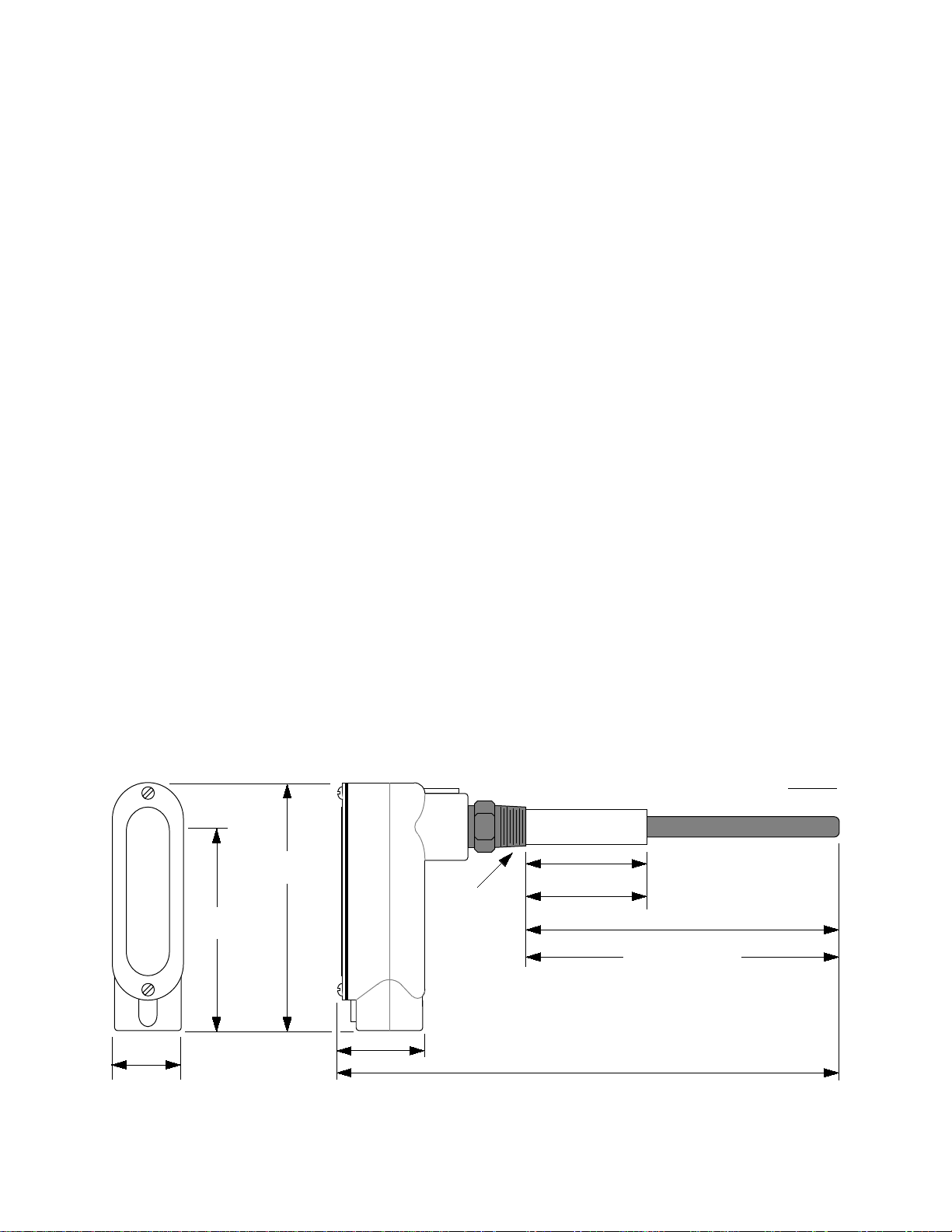
Overall Size ............................ 16.5 X 6.1 X 1.8 inches(419 X 155 X 46 mm)
Weight .......................................................................................... 2 lb (4.4 kg)
1.75
(45)
LV750
6.10
(155)
5.00*
(127)
*MINIMUM TURNING
RADIUS REQUIRED
FOR INSTALLATION
INSULATOR
LENGTH
1/2" NPT
DIMENSIONS SHOWN ARE FOR STANDARD UNIT.
PROBE LENGTHS TO 72 INCHES (1830 MM) ARE
2.10
(53)
4.00
(102)
AVAILABLE ON SPECIAL ORDER.
16.50
(419)
Figure 2.1: Overall Dimensions
3
DIMENSIONS:
12.00
(305)
PROBE LENGTH
INCHES
MM
11/16/01

3.0 INSTALLATION AND CALIBRATION
3.1 After unpacking the unit, inspect it for any evidence of shipping damage. Any
claims for damage due to shipping must be filed with the carrier who handled
the package(s).
3.2 Select a mounting location for the LV750 unit and its attached sensing probe.
See Figure 3.1 for recommended mounting practices. Figure 3.2 shows some
mounting methods which have proven to be troublesome. Be sure that there is
sufficient clearance around the mounting position to allow for the turning
radius as the unit is screwed into place. Also, in the case of rigid probes,
allow sufficient room to be able to insert the probe into the opening in the
vessel. Cut a hole in the vessel that is at least large enough to allow the
insulator portion of the probe to extend into the inside of the vessel and mount
a threaded coupling to the vessel. The thread size of the coupling should be
1/2" NPT for standard probes. A 3/4" NPT fitting is required for some of the
optional probes.
CAUTION: WHEN MAKING THE OPENING IN THE VESSEL, OBSERVE
ALL SAFETY REQUIREMENTS OF THE AREA IN WHICH THE WORK IS
BEING DONE. BE ESPECIALLY CAREFUL OF PRESSURIZED VESSELS.
CAUTION: SHOULD IT BE NECESSARY TO REMOVE THE PROBE
ASSEMBLY FROM THE HOUSING FOLLOW THE DISASSEMBLY
INSTRUCTIONS IN PARAGRAPHS 3.13 AND 3.14.
3.3 Screw the LV750 unit into the coupling and install conduit suitable to the
environment in which the unit is to be used. See Figure 3.1 for a suggested
conduit arrangement.
3.4 Wire the LV750 unit in accordance with the typical wiring diagrams of
Figure 3.3, 3.4, or 3.5 or as may be required by the particular application in
which the unit is to be used. Because of the extremely wide range of control
and/or alarm applications in which the unit may be used, it is not possible to
show all conceivable wiring diagrams. Consult OMEGA Engineering if
assistance is desired.
CAUTION: BE SURE THAT ALL WIRING CONFORMS TO THE REQUIREMENTS
OF THE NATIONAL ELECTRICAL CODE AND ANY ENFORCING AUTHORITIES OR
AGENCIES HAVING JURISDICTION OVER THE INSTALLATION.
LV750 4 11/30/01
 Loading...