

Page 1
LV-1201, LV-1202, LV-1203
Non-Magnetic, Side Mount
Liquid Level Switches
INSTRUCTION
SHEET
M0776/0104
1. GENERAL DESCRIPTION
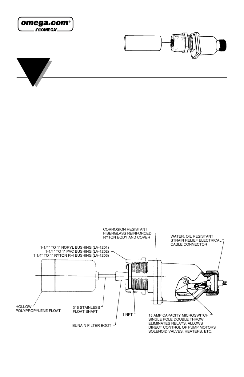
The OMEGA®LV-1200 Series Switches feature a non-magnetic design
suitable for application where magnetic particles (ie: rust) are present. The
LV-1200 Series features a plastic and 316 SS construction, or a Hastelloy C
construction for more corrosive applications.
The LV-1200 Series can be used in highly particle contaminated liquids such
as sewage, machine cutting oils and medium slurries under conditions of
crystallization liquid surface, drying-caking at liquid-air interference, and
scum formations.
With the LV-1200 Series, particle contamination resistance is provided by a
flexible filter boot which prevents crystallization, caking, heavy dirt
concentration, slurries, scum, etc, from affecting the operation of the unit.
FEATURES
• Rugged Industrial Design
• Non-Magnetic Design Suitable for Rusty Enviromnents;
• 15A SPDT Switch Directly Controls Pump
Page 2

SPECIFICATIONS FOR MODELS LV-1201, & LV-1202
• Model LV-1201 (NORYL®PPO)
For use in water, acids, bases, inorganic solutions, sewage, contaminated
water
• Wetted Surfaces
Noryl
®
Engineering Plastic (PPO), 316 SS Stainless Steel, Hypalon
®
• Nominal Working
Temperature & Pressure
Temperature (°F) 200 Max.
Pressure (PSIG) 75 Operating
100 Max. Non-Operating
• LV-1202 (FORTRON
®
PPS)
(Broad Chemical Spectrum)
For use in acids, bases, inorganic solutions, alcohols ketones, chlorinated
organics, esters, ether, hydrocarbons, nitrites, phenols
• Wetted Surfaces
Fortron
®
Engineering Plastic (PPO), 316 SS Stainless Steel, Viton
®
• Nominal Working
Temperature & Pressure
Temperature (°F) 200 Max.
Pressure (PSIG) 75 Max. Operating
100 Max. Non-Operating
• Working Fluid Spec. Gravity
Model 1201 0.6 Min.
Model 1202 0.7 Min.
Model 1203 0.7 Min.
• Electrical Switch Characteristics
SPDT UL and CSA listed
15 AMP @ 1/2 HP: 125/250 Vac
1/2 AMP @ 125 Vdc, 1/4 AMP @ 250 Vdc
5 AMP 125 Vac (Tungsten Lamp Load)
10,000,000 Operation Median.
2
Page 3
3
II. SPECIFICATIONS FOR MODELS LV-11201, & LV-1202 con’t
• SPDT-Dry Circuit
Gold Cross bar Contacts for Computer/ PLC Interfaces
1.0 AMP or less 5-24 Vac/Dc (UL & CSA Listed)
• Liquid Level Change to Activate Switch:
-6.35 mm (-1/4") All Models
• Weight:
0.22 kg. (1/2 lb) All Models
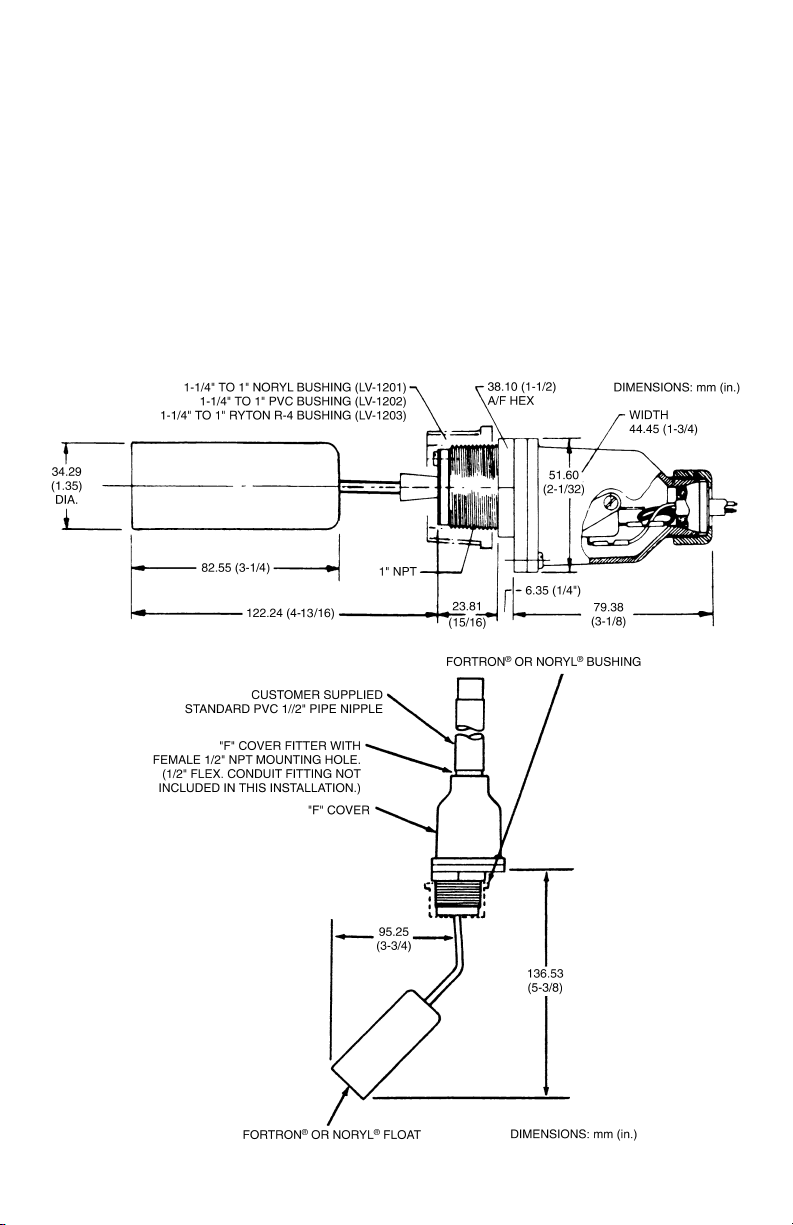
• INSTALLATION DIMENSIONS
Page 4
4
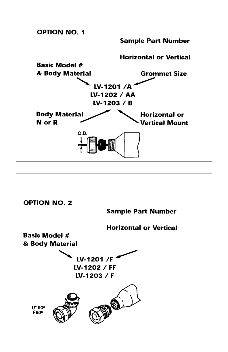
III. INPUT POWER CABLE INTERFACE OPTIONS
GROMMET CABLE GROMMET CABLE
SIZE O. D. SIZE O. D.
A 6.35 mm (0.25 in.) B 9.40 mm (0.37 in.)
AA 7.62 mm (0.30 in.) C 12.70 mm (0.50 in.)
12.70 mm (1/2") Flexible
Conduit Fitting
12.70 mm (1/2") STRAIGHT
F
Page 5

5
ASSEMBLY WARNING
THE LV-1200 SERIES EMPLOY AN EXTERNAL SEAL SHAFT (A), A
FLEXIBLE ELASTOMER DIAPHRAGM SEAL (B), AND AN INTERNAL
FEED THRU SHAFT OR SWITCH ACTUATING ARM (D) - REFER TO
DIAGRAM BELOW. ALL THREE ELEMENTS ARE ASSEMBLED AND
LOCKED IN PLACE WITH LOCTITE ADHESIVE. TO PREVENT
RUPTURE OF SEAL AND LEAKAGE INTO SWITCH AREA, IT IS
CRITICALLY IMPORTANT THAT TORQUE NOT BE APPLIED TO SEAL
SHAFT (A), FLOAT SHAFT (E) OR DRAG DISK ARM (E), DURING
CHANGE OF FLOAT OR DISK DRAG.
IF FLOAT SHAFT OR DRAG DISK ARM (E) REQUIRE REPLACEMENT,
IT IS NECESSARY TO REMOVE FILTER BOOT (F). SEAL SHAFT (A)
MUST THEN BE HELD FIRMLY IN A VISE OR WITH PLIERS WHILE (E)
IS THREADED AND A NEW SHAFT IS ASSEMBLED.
LV-1200 Series are NOT explosion-proof devices.
NOTE
Page 6

6
IV. INSTALLATION AND OPERATION
The LV-1200 Series Liquid Level Switch is for side-mounting ONLY. It is
supplied with a 1
1
⁄2" or 11⁄4" x 1" bushing (Noryl®, Model LV-1201; PVC,
Model LV-1202, and Ryton R-4 for Model LV-1203) threaded in place with 2
to 3 wraps of Teflon
®
tape, which must be intact or renewed if the bushing
and switch are separated before assembly in tank. Care must be exercised
when threading the bushing into plastic or metal fittings. Apply a minimum
of 2 to a maximum of 3 wraps of Teflon tape to the threads of the bushing.
This is especially important if the unit is to be used in metal fittings where
coarse metal threads could gall plastic if not lubricated. The plastic bushing
CAN BE CRACKED
if the main body of the level switch is tightened into it
FIRST
. Cracking will not occur if the bushing is FIRST tightened into the
pipe or tank fitting and THEN
the LV-1200 body is tightened into the
bushing.
Therefore:
Step 1. Teflon tape thread and tighten plastic bushing into pipe or
tank fitting.
Step 2. Teflon tape thread and tighten the LV-1200 Switch into plastic
bushing by applying wrench to hexagon section. Repeat steps 1
and 2 until arrow on the body points UPWARD and the threads
are leak tight.
Plumbers tools such as pipe wrenches are not recommended if
possible, use a “Rigid” type wrench where the smooth jaws
closely fit the hexagon section.
V. ELECTRICAL WIRING
1. Remove the gland nut, grommet and switch cover
2. Strip the outer jacket of the electrical cord back approximately 32 mm
(1
1
⁄4"). Strip the insulation from the individual conductors back
approximately 6 mm (
1
⁄4").
3. Slip on terminals are supplied with each switch. Remove them from the
switch terminals and crimp on or solder to the electrical leads.
4. Feed the electrical cable through the gland nut, grommet and switch
cover as shown below.
NOTE
Page 7

7
V. ELECTRICAL WIRING Con't
5. Apply slip on terminals to appropriate contacts of the microswitch.
6. Slide the cover down the cable and fasten it to the body of the switch with
the 4 screws provided.
7. Slide the grommet down the cable until the outer jacket is level with the
small end of the grommet and then push the grommet into the tapered
end of the cover.
8. Hold the cable jacket to prevent rotation and thread the gland nut firmly
onto the cover.
Figure 1: Wiring Schematic for power applied to the load when the liquid
level is less than the set point (power to the load is interrupted when the
level increases to above the set point.)
Figure 2: Wiring Schematic for power applied to the load when the liquid
level is greater than the set point (power to the load is interrupted when the
level decreases to above the set point.)
Microswitch actuation point may be monitored by an audible click or with
an OHM meter before connecting the line power to the terminal strip or by
monitoring the voltage supplied to the load through the microswitch.
Page 8

8
LV-1201 AND LV-1202 PARTS LIST DIAGRAM
Page 9

9
LV-1201 PARTS LIST DIAGRAM
Page 10

10
LV-1202 PARTS LIST DIAGRAM
Page 11

11
LV-1203 PARTS LIST DIAGRAM
Page 12

It is the policy of OMEGA to comply with all worldwide safety and EMC/EMI regulations that apply. OMEGA is constantly pursuing certification of its
products to the European New Approach Directives. OMEGA will add the CE mark to every appropriate device upon certification.
The information contained in this document is believed to be correct, but OMEGA Engineering, Inc. accepts no liability for any errors it contains, and reserves the right to alter
specifications without notice.
WARNING: These products are not designed for use in, and should not be used for, human applications.
WARRANTY/DISCLAIMER
OMEGA ENGINEERING, INC. warrants this unit to be free of defects in materials and workmanship for a period of 13 months from
date of purchase. OMEGA’s WARRANTY adds an additional one (1) month grace period to the normal one (1) year product
warranty to cover handling and shipping time. This ensures that OMEGA’s customers receive maximum coverage on each
product.
If the unit malfunctions, it must be returned to the factory for evaluation. OMEGA’s Customer Service Department will issue an
Authorized Return (AR) number immediately upon phone or written request. Upon examination by OMEGA, if the unit is found to be
defective, it will be repaired or replaced at no charge. OMEGA’s WARRANTY does not apply to defects resulting from any action of the
purchaser, including but not limited to mishandling, improper interfacing, operation outside of design limits, improper repair, or
unauthorized modification. This WARRANTY is VOID if the unit shows evidence of having been tampered with or shows evidence of
having been damaged as a result of excessive corrosion; or current, heat, moisture or vibration; improper specification;
misapplication; misuse or other operating conditions outside of OMEGA’s control. Components which wear are not warranted,
including but not limited to contact points, fuses, and triacs.
OMEGA is pleased to offer suggestions on the use of its various products. However, OMEGA neither assumes responsibility
for any omissions or errors nor assumes liability for any damages that result from the use of its products in accordance with
information provided by OMEGA, either verbal or written. OMEGA warrants only that the parts manufactured by it will be as
specified and free of defects. OMEGA MAKES NO OTHER WARRANTIES OR REPRESENTATIONS OF ANY KIND
WHATSOEVER, EXPRESS OR IMPLIED, EXCEPT THAT OF TITLE, AND ALL IMPLIED WARRANTIES INCLUDING ANY
WARRANTY OF MERCHANTABILITY AND FITNESS FOR A PARTICULAR PURPOSE ARE HEREBY DISCLAIMED. LIMITATION
OF LIABILITY: The remedies of purchaser set forth herein are exclusive, and the total liability of OMEGA with respect to this
order, whether based on contract, warranty, negligence, indemnification, strict liability or otherwise, shall not exceed the
purchase price of the component upon which liability is based. In no event shall OMEGA be liable for consequential,
incidental or special damages.
CONDITIONS: Equipment sold by OMEGA is not intended to be used, nor shall it be used: (1) as a “Basic Component” under 10 CFR
21 (NRC), used in or with any nuclear installation or activity; or (2) in medical applications or used on humans. Should any Product(s)
be used in or with any nuclear installation or activity, medical application, used on humans, or misused in any way, OMEGA assumes
no responsibility as set forth in our basic WARRANTY/DISCLAIMER language, and, additionally, purchaser will indemnify OMEGA and
hold OMEGA harmless from any liability or damage whatsoever arising out of the use of the Product(s) in such a manner.
RETURN REQUESTS / INQUIRIES
Direct all warranty and repair requests/inquiries to the OMEGA Customer Service Department. BEFORE RETURNING ANY
PRODUCT(S) TO OMEGA, PURCHASER MUST OBTAIN AN AUTHORIZED RETURN (AR) NUMBER FROM OMEGA’S CUSTOMER
SERVICE DEPARTMENT (IN ORDER TO AVOID PROCESSING DELAYS). The assigned AR number should then be marked on the
outside of the return package and on any correspondence.
The purchaser is responsible for shipping charges, freight, insurance and proper packaging to prevent breakage in transit.
FOR WARRANTY
RETURNS, please have the following informa-
tion available BEFORE contacting OMEGA:
1. Purchase Order number under which the product was
PURCHASED,
2. Model and serial number of the product under warranty, and
3. Repair instructions and/or specific problems relative to the
product.
FOR NON-WARRANTY REPAIRS,
consult OMEGA for current repair charges. Have the following information available BEFORE contacting OMEGA:
1. Purchase Order number to cover the COST of the repair,
2. Model and serial number of the product, and
3. Repair instructions and/or specific problems relative to
the product.
OMEGA’s policy is to make running changes, not model changes, whenever an improvement is possible. This affords our customers the latest in
technology and engineering.
OMEGA is a registered trademark of OMEGA ENGINEERING, INC.
© Copyright 2003 OMEGA ENGINEERING, INC. All rights reserved. This document may not be copied, photocopied, reproduced, translated, or
reduced to any electronic medium or machine-readable form, in whole or in part, without the prior written consent of OMEGA ENGINEERING,
INC.
Servicing North America:
USA: One Omega Drive, Box 4047
ISO 9001 Certified Stamford CT 06907-0047
Tel: (203) 359-1660 FAX: (203) 359-7700
e-mail: info@omega.com
Canada: 976 Bergar
Laval (Quebec) H7L 5A1, Canada
Tel: (514) 856-6928 FAX: (514) 856-6886
e-mail: info@omega.ca
For immediate technical or application assistance:
USA and Sales Service: 1-800-826-6342 / 1-800-TC-OMEGA
®
Canada: Customer Service: 1-800-622-2378 / 1-800-622-BEST
®
Engineering Service: 1-800-872-9436 / 1-800-USA-WHEN
®
TELEX: 996404 EASYLINK: 62968934 CABLE: OMEGA
Mexico: En Espan˜ol: (001) 203-359-7803 e-mail:espanol@omega.com
FAX: (001) 203-359-7807 info@omega.com.mx
OMEGAnet®Online Service Internet e-mail
www.omega.com info@omega.com
Servicing Europe:
Benelux: Postbus 8034, 1180 LA Amstelveen, The Netherlands
Tel: +31 (0)20 3472121 FAX: +31 (0)20 6434643
Toll Free in Benelux: 0800 0993344
e-mail: sales@omegaeng.nl
Czech Frystatska 184, 733 01 Karviná, Czech Republic
Republic: Tel: +420 (0)59 6311899 FAX: +420 (0)59 6311114
Toll Free: 0800-1-66342 e-mail: info@omegashop.cz
France: 11, rue Jacques Cartier, 78280 Guyancourt, France
Tel: +33 (0)1 61 37 2900 FAX: +33 (0)1 30 57 5427
Toll Free in France: 0800 466 342
e-mail: sales@omega.fr
Germany/ Daimlerstrasse 26, D-75392 Deckenpfronn, Germany
Austria: Tel: +49 (0)7056 9398-0 FAX: +49 (0)7056 9398-29
Toll Free in Germany: 0800 639 7678
e-mail: info@omega.de
United One Omega Drive, River Bend Technology Centre
Kingdom: Northbank, Irlam, Manchester
ISO 9002 Certified M44 5BD United Kingdom
Tel: +44 (0)161 777 6611 FAX: +44 (0)161 777 6622
Toll Free in United Kingdom: 0800-488-488
e-mail: sales@omega.co.uk
 Loading...