

Page 1
J-15
⻬ Complete Isolation
with Optical Couplers
and Power DC-to-DC
Converter
⻬ Industrial Surge
Protection Devices
⻬ Six LED Diagnostic
Indicators
⻬ 19.2K Baud at 3 Miles
(5KM), 57.6K Baud at
0.5 Miles (0.8KM)
⻬ Request-to-Send, Clear-
to-Send Handshake
⻬ Tri-State Outputs for
Multidrop Applications,
up to 64 Devices
⻬ Selection of Connectors
⻬ Wide Operating
Temperature Range
⻬ Solderless Screw
Terminal Field
Connections
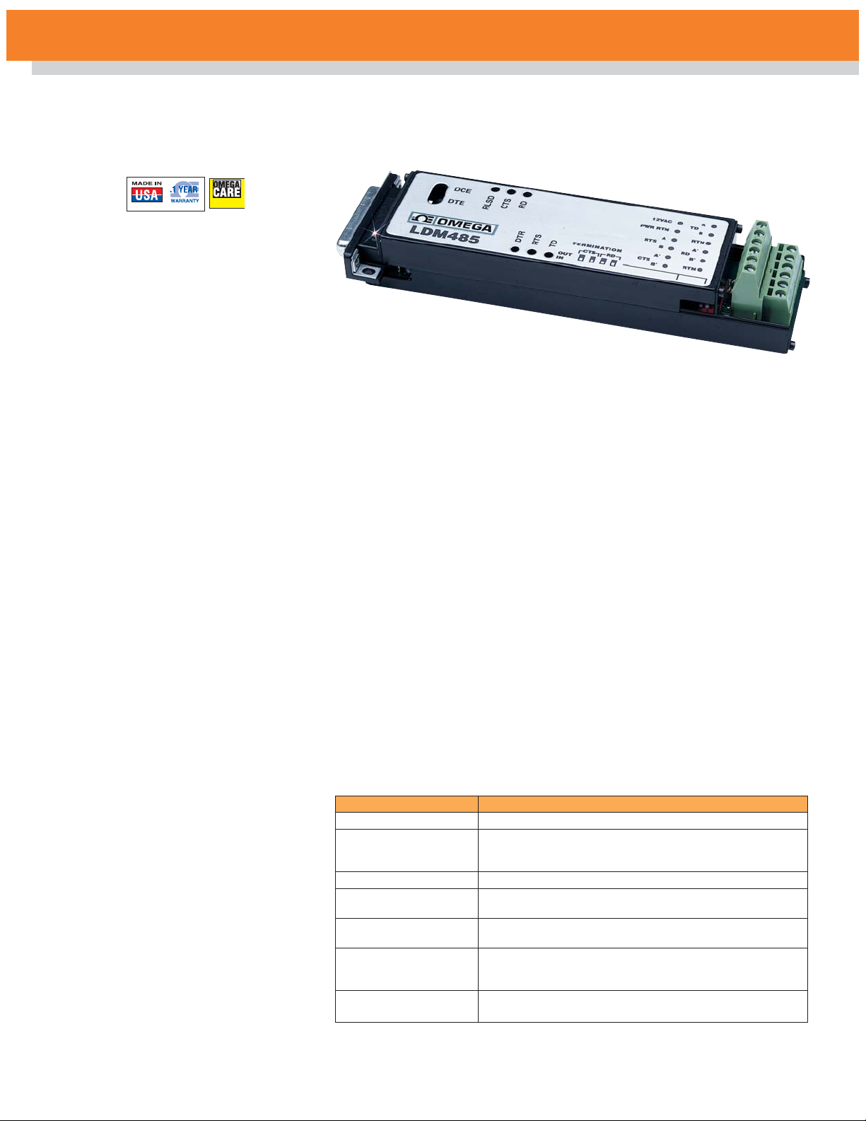
LDM485
Fully Isolated Limited Distance Modem, RS-232/422 Converter
The LDM485 is a compact RS-232
to RS-485 con verter which fea tures
a complete electrical iso la tion
bar rier and heavy duty elec tri cal
surge protectors. These devices
feature a rugged alu mi num
enclosure small enough to mount on
the back panel of typical computer
equipment, saving valuable desk
and floor space. Isolation is
pro vided by optical couplers and a
DC-to-DC converter. The RS-232
con nec tion is through male or
female EIA 25-pin con nec tors. The
RS-485 connections are made
through con ven ient solderless
screw terminals.
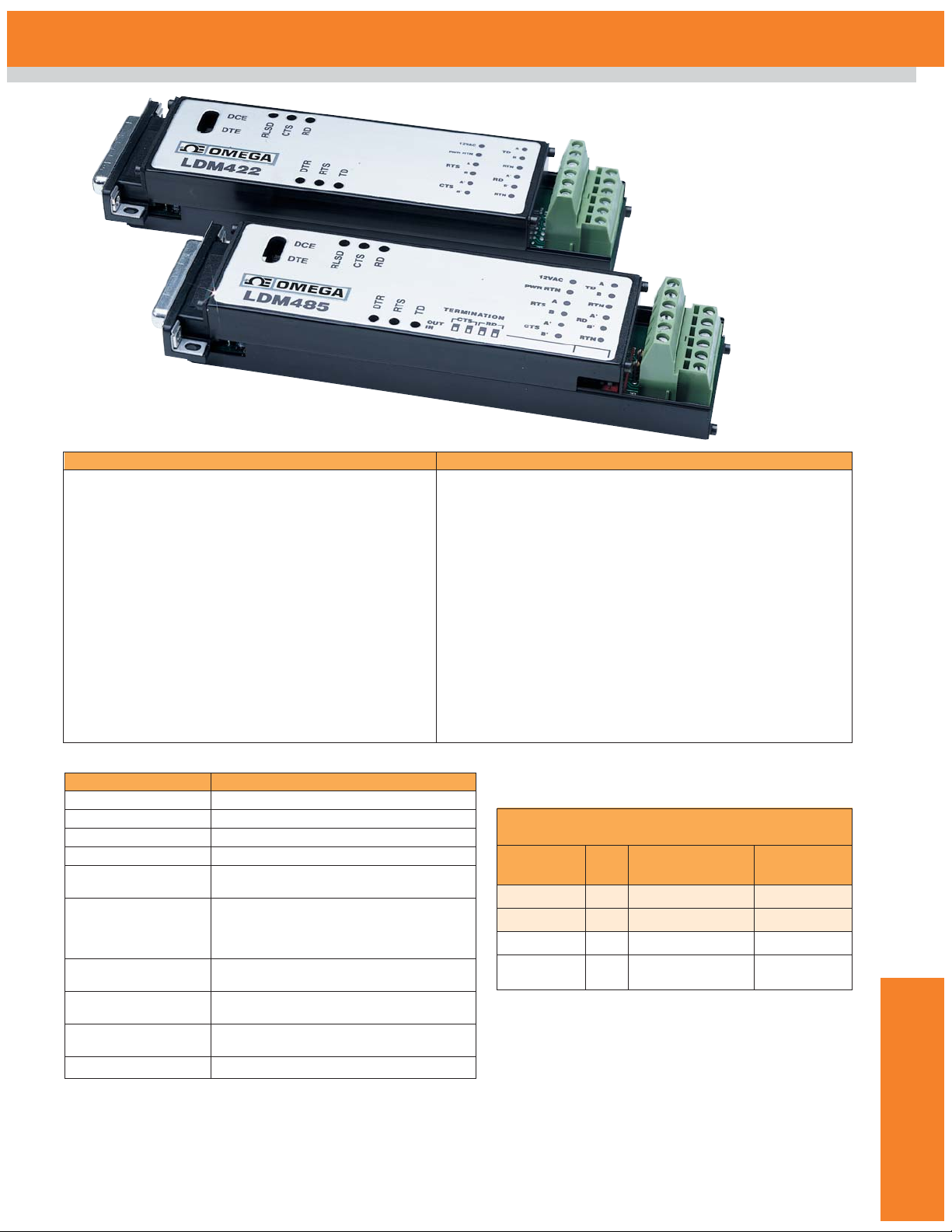
The LDM485 series is designed for
full duplex op era tion over two-wire
pairs. Outputs are tri-state, allowing
multidropping of up to 64 units.
Hardware hand shake is available
over two separate wire pairs. Data
rates are DC to 57.6k baud. Six
diagnostic LED indicators are
provided (see Figure 1) for
in stal la tion guid ance and system
trou bleshoot ing. The RS-232
SPECIFICATIONS
Model LDM485
Baud Rate Range 0 – 57.6K
Baud Rate 57.6K 38.4K 19.2K 9.6K 4.8K 2.4K – 0
Distance (miles)
(1)
0.5 1 3 4 5 8
Distance (km) 0.8 1.7 5 6.7 8.3 13.3
Wire Capacitance Equal to 25pF per foot and up to 32 multidrop units
Maximum
Multidrop Units 64
Common Mode Surge: 1500V
Isolation Continuous: 1000V
Differential Mode (AC input)
Surge Protection ANSI/IEEE C37.90.1-1989
(9 devices) (all RS-485 inputs and outputs)
Modes Asynchronous 4-wire duplex, 2-wire half-duplex,
2-wire simplex
interface sup ports Request To
Send, Clear To Send, Data Set
Ready, Re ceived Line Signal
Detect, and Data Ter mi nal Ready.
A convenient null modem switch is
pro vided for the data lines. Also, a
line termination switch connects a
line termination resistor and line
bias re sis tors to the RS-485 receive
lines. The RS-485 interface
supports Request To Send and
Clear To Send on separate wire
pairs. The LDM485 may be used to
convert two sets of send and
receive channels by using RTS and
CTS circuits as the second data
channels. Data rates are the same.
The units use 12VAC from a
wall-mounted transformer to screw
terminals 1 and 2 on the RS-485
con nec tor. Al ter nate ly, they can use
±12VDC to pins 9 (+) and 10 (–) of
the RS-232 connector.
The LDM485 conforms to EIA
RS-232 and RS-485 specifications.
Data Ter mi nal Ready must be
asserted by the host RS-232 port
before the LDM485 can transmit
data. When Data Ter mi nal Ready is
not as serted, all outputs of the
LDM485 are high impedance,
allowing up to 64 LDM485 units to
be mul tidrop ped on a common
com mu ni ca tions cable. See Figures
1 and 3 for details.
Request To Send and Clear To
Send are carried through the
RS-485 port as two separate wire
pairs. These may be used for full
duplex flow control.
Data Terminal Ready, DTR, must
be asserted before the LDM485 can
trans mit data. This is normally done
by the host computer. For situations
where the host equipment does not
have the capability of supplying a
DTR signal, RLSD may be used to
automatically assert DTR. On the
RS-232 connector P1 of each
LDM485, simply connect RLSD
pin 8 to DTR pin 20. This
con nec tion is not ap pro pri ate for
multi-drop installations.
Notes: (1) Distances reduced if multidropping more than 32 units; by 30% for 33-48 units, 50%
for 49-64.
$
287
Basic Unit
LDM485-P, $287, shown
smaller than actual size
SM
Extended Warranty
Program
Page 2
J
J-16
To Order
(Specify Model No.)
Power
Model No. Price RS232 Connector Source
LDM485-P $287 25 Pin male Host-powered
LDM485-S 287 25 Pin female Host-powered
LDM485-PT 305 25 Pin male Transformer
LDM485-ST 305 25 Pin female Transformer
Includes operator’s manual. Transformer powered units also
include 120 Vac wall mount transformer.
Ordering Example: LDM485-ST converter: $305.
Notes: (2) TD = Transmit Data, RD = Receive Data, RTS = Request To
Send, CTS = Clear To Send, DTR = Data Terminal Ready, DSR = Data
Set Ready, RLSD = Received Line Signal Detect. (3) 120VAC and 220
VAC power transformers are available. (4) Ground-benign environmental
conditions (no salt atmosphere, <50°C ambient temperature).
Model LDM485
Channel Lines
(2)
TD, RD, RTS, CTS
Control Lines
(2)
RTS, CTS, DTR, DSR, RLSD
Null Modem Switch 1 (Reverses RS-232 pins 2 and 3)
RS-485 Output Drive 60mA max/output
RS-485 Input
Impedance 12kΩ min/input
Power:
AC operation
(3)
12VAC, ±10%, 10W screw terms 1 & 2
DC operation +11.5 to +17VDC @ 500mA on pin 9
-11.5 to -17VDC @ 100mA on pin 10
Operating 0°C to +70°C, 0-95% relative humidity,
Environment noncondensing
Dimensions 53.3 mmH x 167.6 mmW x 32.5 mmD
(2.1 x 6.6 x 1.28")
Weight 200 g (7 oz) max
AC Transformer 311.8 g (11.0 oz) max
MTBF
(4)
>100,000 hrs
RS-232 P1 Pin Descriptions RS-485 P2 Pin Descriptions
Pin 1 Case Case Ground Pin 1 12VAC
Pin 2 TD Transmit DataPin 2 PWR RTN
Pin 3 RD Receive Data Pin 3 RTS A
Pin 4 RTS Request To Send Pin 4 RTS B
Pin 5 CTS Clear To Send Pin 5 CTS A'
Pin 6 DSR Data Set Ready Pin 6 CTS B'
(connected to Data Pin 7 TD A
Terminal Ready) Pin 8 TD B
Pin 7 Sig Gnd Signal Ground Pin 9 SIG RTN
Pin 8 RLSD Receive Line Signal Detect Pin 10 RD A'
Pin 9 +12VDC Positive DC Supply Input Pin 11 RD B'
Pin 10 –12VDC Negative DC Supply Input Pin 12 SIG RTN
Pin 16 Echo Sup Echo Suppression
(tie to pin 17 to enable)
Pin 17 Echo Sup Echo Suppression
(tie to pin 16 to enable)
Pin 20 DTR Data Terminal Ready
(connected to Data
Set Ready)
MOST POPULAR
MODELS HIGHLIGHTED
Page 3

One Omega Drive | Stamford, CT 06907 | 1-888-TC-OMEGA (1-888-826-6342) | info@omega.com
EPG05
www.omega.com
UNITED KINGDOM
www. omega.co.uk
Manchester, England
0800-488-488
UNITED STATES
www.omega.com
1-800-TC-OMEGA
Stamford, CT.
CANADA
www.omega.ca
Laval(Quebec)
1-800-TC-OMEGA
GERMANY
www.omega.de
Deckenpfronn, Germany
0800-8266342
Karviná, Czech Republic
FRANCE
www.omega.fr
Guyancourt, France
088-466-342
CZECH REPUBLIC
www.omegaeng.cz
596-311-899
BENELUX
www.omega.nl
Amstelveen, NL
0800-099-33-44
More than 100,000 Products Available!
Temperature
Calibrators, Connectors, General Test and Measurement
Instruments, Glass Bulb Thermometers, Handheld Instruments
for Temperature Measurement, Ice Point References,
Indicating Labels, Crayons, Cements and Lacquers, Infrared
Temperature Measurement Instruments, Recorders Relative
Humidity Measurement Instruments, RTD Probes, Elements
and Assemblies, Temperature & Process Meters, Timers and
Counters, Temperature and Process Controllers and Power
Switching Devices, Thermistor Elements, Probes and
Assemblies,Thermocouples Thermowells and Head and Well
Assemblies, Transmitters, Wire
Flow and Level
Air Velocity Indicators, Doppler Flowmeters, Level
Measurement, Magnetic Flowmeters, Mass Flowmeters,
Pitot Tubes, Pumps, Rotameters, Turbine and Paddle Wheel
Flowmeters, Ultrasonic Flowmeters, Valves, Variable Area
Flowmeters, Vortex Shedding Flowmeters
pH and Conductivity
Conductivity Instrumentation, Dissolved Oxygen
Instrumentation, Environmental Instrumentation, pH
Electrodes and Instruments, Water and Soil Analysis
Instrumentation
Data Acquisition
Auto-Dialers and Alarm Monitoring Systems,
Communication Products and Converters, Data
Acquisition and Analysis Software, Data Loggers
Plug-in Cards, Signal Conditioners, USB, RS232, RS485
and Parallel Port Data Acquisition Systems, Wireless
Transmitters and Receivers
Pressure, Strain and Force
Displacement Transducers, Dynamic Measurement
Force Sensors, Instrumentation for Pressure and Strain
Measurements, Load Cells, Pressure Gauges, Pressure
Reference Section, Pressure Switches, Pressure Transducers,
Proximity Transducers, Regulators,
Strain Gages, Torque Transducers, Valves
Heaters
Band Heaters, Cartridge Heaters, Circulation Heaters,
Comfort Heaters, Controllers, Meters and Switching
Devices, Flexible Heaters, General Test and Measurement
Instruments, Heater Hook-up Wire, Heating Cable
Systems, Immersion Heaters, Process Air and Duct,
Heaters, Radiant Heaters, Strip Heaters, Tubular Heaters
click here to go to the omega.com home page
 Loading...