

Page 1
LD610 Series
B.I.C.M.
Displacement Transducers
With In-Line Signal
Conditioners
omega.com
e-mail: info@omega.com
For latest product manuals:
omegamanual.info
User’s Guide
Shop online at
Page 2

Servicing North America:
USA:
One Omega Drive, Box 4047
ISO 9001 Certified
Stamford CT 06907-0047
Tel: (203) 359-1660 FAX: (203) 359-7700
e-mail: info@omega.com
Canada:
976 Bergar
Laval (Quebec) H7L 5A1, Canada
Tel: (514) 856-6928 FAX: (514) 856-6886
e-mail: info@omega.ca
For immediate technical or application assistance:
USA and Canada:
Sales Service: 1-800-826-6342 / 1-800-TC-OMEGA
®
Customer Service: 1-800-622-2378 / 1-800-622-BEST
®
Engineering Service: 1-800-872-9436 / 1-800-USA-WHEN
®
TELEX: 996404 EASYLINK: 62968934 CABLE: OMEGA
Mexico:
En Espan˜ ol: (001) 203-359-7803 e-mail: espanol@omega.com
FAX: (001) 203-359-7807 info@omega.com.mx
Servicing Europe:
Benelux:
Postbus 8034, 1180 LA Amstelveen, The Netherlands
Tel: +31 (0)20 3472121 FAX: +31 (0)20 6434643
Toll Free in Benelux: 0800 0993344
e-mail: sales@omegaeng.nl
Czech Republic:
Frystatska 184, 733 01 Karvina´, Czech Republic
Tel: +420 (0)59 6311899 FAX: +420 (0)59 6311114
Toll Free: 0800-1-66342 e-mail: info@omegashop.cz
France:
11, rue Jacques Cartier, 78280 Guyancourt, France
Tel: +33 (0)1 61 37 2900 FAX: +33 (0)1 30 57 5427
Toll Free in France: 0800 466 342
e-mail: sales@omega.fr
Germany/Austria:
Daimlerstrasse 26, D-75392 Deckenpfronn, Germany
Tel: +49 (0)7056 9398-0 FAX: +49 (0)7056 9398-29
Toll Free in Germany: 0800 639 7678
e-mail: info@omega.de
United Kingdom:
One Omega Drive, River Bend Technology Centre
ISO 9002 Certified
Northbank, Irlam, Manchester
M44 5BD United Kingdom
Tel: +44 (0)161 777 6611 FAX: +44 (0)161 777 6622
Toll Free in United Kingdom: 0800-488-488
e-mail: sales@omega.co.uk
OMEGAnet®Online Service Internet e-mail
www.omega.com info@omega.com
It is the policy of OMEGA to comply with all worldwide saf ety and EMC/EMI regulations that
apply. OMEGA is constantly pursuing certification of its p roducts to the European New Approach
Directives. OMEGA will add the CE mark to every appropriat e device upon certification.
The information contained in this document is believed to be correct, but OMEGA Engineering, Inc. accepts
no liability for any errors it contains, and reserves the right to alter specifications without notice.
WARNING: These produc ts are not designed for u se in, and should not be used for, human applicati ons.
Page 3

LD610
M-3342 08/09
Index
Section Title Page
Index . . . . . . . . . . . . . . . . . . . . . . . . . . 1
1.0 Introduct ion . . . . . . . . . . . . . . . . . 2
2.0 Technical Specification . . . . . . . . . . . . . . . 3
3.0 Operational and Set-Up G uide - BI CM Kit . . . 6
3.1 Introduction . . . . . . . . . . . . . . . . . . . . . . 6
3.2 Screen Connection . . . . . . . . . . . . . . . . . 8
3.3 Gain Adjustment . . . . . . . . . . . . . . . . . . . 10
3.4 Offset . . . . . . . . . . . . . . . . . . . . . . . . 10
3.5 Set Up Using Fixed Value Resistors . . . . . 11
3.6 Gain Set Up Procedure . . . . . . . . . 13
3.7 Offset Set Up Procedure . . . . . . . . . 14
4.0 The Case . . . . . . . . . . . . . . . . . . . . . . . . . . 16
5.0 The "Why Doesn 't it Work Guide" . . . . . . 17
6.0 Application Notes . . . . . . . . . . . . . . . . . . . . 18
6.1 Transducer Installation . . . . . . . . . . . . . . . . 18
6.2 Example 1 . . . . . . . . . . . . . . . . . . . . . 22
6.3 Example 2 . . . . . . . . . . . . . . . . . . . . . 23
1
Page 4

M-3342 08/09
LD610
1.0: Introduction & Glossary
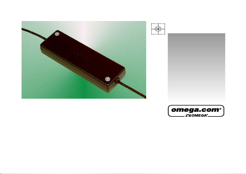
The Boxed Inline Conditioning Module (BICM) is an electronics module that may be used with a wide range of LVDT transducers. Layout and size are
designed to allow the BICM to be easily fitted inline with the transducer cable and installed with the minimum of effort (or changed if ready connected to a
transducer)
The BICM output may be set for a full scale range up to ±10 VDC, offset facilities are provided. The BICM is either powered from a bipolar ±15 VDC supply
or a unipolar ±24 VDC supply depending on product type.
BICM - Boxed Inline Conditioning Unit
Gain - The output voltage per mm of transducer stroke
Offset - The output voltage when the transducer core is at null
P.C.B. - Printed Circuit Board
NPV - Nearest Preferred Value. A resistor selected from a standard range of value
(E24, E48, etc.) that is closest to the required value
BICM kits are supplied for user connection to an LVDT transducer.
2
1.0: Introduction
Page 5

M-3342 08/09
LD610
Standard BICM IP67 BICM
Bipolar Supply Unipolar Supply Bipolar Supply
Power Requirement
Voltage ±15 V ±1.5 V 24 V ±2.4 V ±15 V ±1.5 V
Current
±15 mA nominal
30 mA nominal ±15 mA nominal
Transducer Excitation
Primary Voltage 2 Vrms nominal
Primary Frequency
1
5 kHz typical
Primary Current 10 mA nominal
Signal Input
Input Voltage Range Up to 2.5 Vrms
Input Load Resistance 100 kW
3
2.0: Technical Specication
Page 6

M-3342 08/09
4
LD610
Standard BICM IP67 BICM
Bipolar Supply Unipolar Supply Bipolar Supply
Signal Output
Voltage Output Up to ±10 V
Current Output 11 mA
Output Ripple <14 mVrms
Output Offset 100%
Temp Co. Gain <0.03% FRO / oC
Temp. Co. Offset <0.025% FRO / oC
Warm up Time 15 minutes recommended
Linearity 2 (electronics only) <0.1% FRO
Bandwidth (-3 dB)
3
250 Hz typical
1
Other frequencies are available on request.
2
The electronics has a specification of <0.1%, the overall linearity is dominated by the transducer.
3
Other bandwidths available on request.
4
2.0: Technical Specication
Page 7

M-3342 08/09
5
LD610
Standard BICM IP67 BICM
Bipolar Supply Unipolar Supply Bipolar Supply
Environmental
Operation Temperature Range 0 - 70 oC
Storage Temperature Range -20 to +85 oC
IP Rating IP40 IP67
Mechanical and Connections
Connections Solder pad or factory fit Factory fit only
Enclosure Size 98.5 x 30.5 x 13.0 mm 73.0 x 20.6 mm
Weight 30 g 75 g
Material ABS 400 Series Stainless Steel
Cable Lengths
All specification limits assume a nominal 3 m cable length between transducer and BICM. The BICM can be mounted up to 10 m from the transducer, but
this may result in reduced performance. Not all transducers can cope with long cable lengths. Cable from the BICM to the processing unit or display should
be limited to 100 m.
5
2.0: Technical Specication
Page 8

M-3342 08/09
LD610
3.1: Introduction
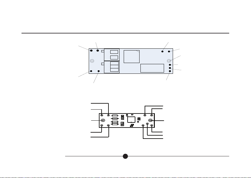
The BICM kit is supplied with a selection of potentiometers and an output cable allowing users to connect LVDT sensors and set up to their own
requirements. Connections are made to the BICM PCB as shown in Fig. 3.1A or Fig. 3.1B below depending on the PCB version.
The BICM output is adjustable for GAIN and OFFSET. See the specification for range of adjustments possible.
Gain is sometimes called span or range. This control will affect the output voltage at the full transducer stroke. Adjusting the control clockwise will increase
the output.
Offset is sometimes called DC shift or zero shift. This control may be used to zero the output if mechanically nulling the transducer is not convenient or
can provide as much as 100% offset to enable the output to be unipolar ie. 0V to 10 V for full transducer stroke. Adjusting the control clockwise will make
output more negative.
Adjustment is by means of trimmer potentiometers (also called variable resistor or pots). The BICM will accept fixed value resistors in place of
potentiometers.
The BICM is designed to accept the following types of potentiometer or resistor:-
Potentiometer - Standard 3/8in square top adjust type potentiometer, see Fig. 3.1 (ie. Bourns 3299 type). The BICM kit comes complete with four
potentiometers.
Resistors - 1/4W MRF4 style.
6
3.0: Operational and Set-Up Guide - BICM Kit
Page 9
M-3342 08/09
LD610
Fig. 3.1A Connections to PCB - 105186 (Bipolar or Unipolar)
Fig. 3.1B Connections to PCB - 103766 (Bipolar only)
7
3.0: Operational and Set-Up Guide - BICM Kit
Yellow
SEC2
SEC1
Green
White
Screen
Primary
Blue
Red
I/O CONNECTIONS
PRI1
PRI2
Screen
VOUT
0V
-15 V
0V
+15 V
Power
Supply
Output
Signal
SEC2
SEC1
Green
White
Screen
Primary
Blue
Red
TRANSDUCER CONNECTIONS
I/O CONNECTIONS
PRI1
PRI2
Screen
VOUT
0V
-15 V
0V
+15 V
Power
Supply
Output
Signal
Yellow
White
Green
Blue
Red
0V (Signal
white
)
Secondary 2 Green
0V Supply
Green
+15 V Bipolar
+24 V Unipolar
Red
Vout Yellow
Gain Offset
R2
+R4
R3
-R4
RV2RV1
R2
R1
Secondary 1 White
Primary Exc 2 Red
Primary Exc1 Blue
-15V Bipolar only
Blue
Screen
Page 10

M-3342 08/09
LD610
3.2: Screen Connection
The screen connection is arranged so that the transducer cable screen and I/O cable screen is connected and that some cable strain relief is
provided whilst setting up the board. Screens are not connected to 0V on the PCB. Screen and 0V may be connected on the PCB by using a wire
link or at the user connection end, for example at the PSU, but it all depends on the installation requirements.
Colours are for Omega LD610 Series transducers. Check individual transducer data sheets before connecting.
If a different polarity output is required secondary connections may be reversed. See application notes.
Centre Tap (CT), yellow wire, connection not required. Ensure no loose wires.
3.2 Screen Connection
Fit the potentiometers in the positions indicated in Fig. 3.3. The table below gives suggested values for use with some Omega LVDT's. Once fitted
the set up procedure can be followed to give the required output.
8
3.0: Operational and Set-Up Guide - BICM Kit
Page 11

M-3342 08/09
LD610
9
3.0: Operational and Set-Up Guide - BICM Kit
TRANSDUCER POTENTIOMETER VALUE (ohms)
GAIN OFFSET
LD610 2.5 100K 5K
LD610 5.0 50K 10K
LD610 10 100K 5K
LD610 15 100K 5K
LD610 25 100K 5K
LD610 50 50K 10K
LD610 100 50K 10K
Fig. 3.3 Component Installation
Top View
Side View
Fit this way round
Transducer
Connection
End
Page 12

M-3342 08/09
LD610
3.3. Gain Adjustment
Gain adjustment is best done before offset adjustment. If an OFFSET potentiometer has been fitted then set this to the mid position.
GAIN SETUP PROCEDURE
1) Adjust the potentiometer to the approximate mid position, about 12 full turns from either end.
2) Adjust the LVDT core position to give 0V output.
3) Move the core to a full scale position either inwards (+ve output) or outwards (-ve output). Adjust the potentiometer value to give the required
full scale output voltage such as + or -10 V. Adjusting the control clockwise will increase the output.
4) Return the core to the null position and check the output. Repeat steps 2 & 3 as required.
3.4. Offset
Any offset required is set by simply adjusting the OFFSET potentiometer until the required positive or negative offset is achieved. Adjusting the
control clockwise will make the output more negative.
Example:- Output required is 0V to +8 V for full transducer stroke (fully out to fully in). Set the gain for an output of 0V ±4 V then apply an offset
of +4 V.
Applying the required offset can sometimes be difficult if the gain is not correctly set. The application notes may help.
If no offset is required it is best not to fit the OFFSET potentiometer.
10
3.0: Operational and Set-Up Guide - BICM Kit
Page 13

M-3342 08/09
LD610
3.5. Set Up Using Fixed Value Resistors
Fit the components into the positions shown in Fig 3.4 once component values have been determined using the set up procedure.
The term nearest preferred value (NPV) is used throughout. This is a resistor selected from standard ranges (E24,E48 etc) that most closely
matches the value required.
Two resistors (in series) may be fitted to allow for more accurate calibration of gain and offset. If only one resistor is required a wire link is fitted
in place of the second resistor.
Gain adjustment is best done before offset adjustment. If an OFFSET potentiometer is fitted, set this to the mid position. If a resistor is fitted,
temporarily disconnect this.
If an offset is to be applied take this into account when setting the gain.
Example:- Output required is 0V to +10 V for full transducer stroke (fully out to fully in). Set the gain for an output of 0V ±5 V then apply an
offset of +5 V.
Some suggested start values for resistors are shown in the table below. If the transducer being used is not in the list then start with an arbitrary
value such as 50 Kohms.
11
3.0: Operational and Set-Up Guide - BICM Kit
Page 14

M-3342 08/09
LD610
TRANSDUCER APPROXIMATE RESISTOR VALUE (ohms)
GAIN OFFSET (+ or -5V)
LD610 1.5 85K 20K
LD610 2.5 61K 13K
LD610 5.0 40K 7K5
LD610 10 70K 15K
LD610 15 52K 11K
LD610 25 51K 11K
LD610 50 39K 7K5
LD610 100 25K 4K3
Fig 3.4 Resistor Positions
12
3.0: Operational and Set-Up Guide - BICM Kit
Page 15

M-3342 08/09
LD610
3.6. Gain Set Up Procedure
If this procedure is to be used to determine the value of potentiometer required perform up to step (6). The potentiometer value will be the NPV
greater than the resistor value determined.
1) Temporarily connect a variable resistance (such as a decade box) to the board as in
Fig. 3.5(a). Set the resistor to an initial value as shown in the table.
Fig 3.5 Temporary Resistor Connections - Gain
2) Move the core to a full scale position either inwards (+ve output) or outwards (-ve output). Adjust the potentiometer value to give the
required full scale output voltage such as + or -10 V.
3) Move the core to the full scale position. Adjust the variable resistor value to give the required full scale output voltage such as + or - 10 V.
4) Return the core to the null position and check the output. Repeat steps 2 & 3 as required.
5) If a single resistor is to be fitted, fit a NPV fixed resistor to position R1. Fit a wire link to position R2. If two resistors are to be used for a more
accurate calibration see step (6)
13
3.0: Operational and Set-Up Guide - BICM Kit
Resistance
Box
Resistance
Box
(a)
(b)
Page 16

M-3342 08/09
LD610
6) Fit a NPV fixed resistor that is just below the value required to position R1. Reconnect the temporary variable resistor to position R2, see Fig 3.6(b).
7) Repeat steps 2 & 3, moving the core between the null position and the full scale position adjusting the variable resistor as necessary to achieve the
required output.
8) Substitute a NPV fixed resistor for the temporary variable resistor position R2.
3.7 Offset Set Up Procedure
It is assumed that the gain has been set up consistent with the overall required result.
1) Set the transducer core to the null position. If this cannot be determined mechanically then, with no OFFSET resistors connected, adjust the core
position for a 0V output.
2) Connect temporary SOT or variable resistors (leads to be kept as short as possible) as shown for the required polarity offset. Fig. 3.6(a) for a positive
offset and Fig. 3.6(b) for a negative offset.
Fig 3.6 Temporary Resistor Connections - Offset
14
3.0: Operational and Set-Up Guide - BICM Kit
Resistance
Box
(a)
(b)
POSITIVE OFFSET
NEGATIVE OFFSET
Resistance
Box
Page 17

M-3342 08/09
LD610
3) Adjust the variable resistance until the required offset is achieved.
4) If a single resistor is to be fitted, fit a NPV fixed resistor to position +R4 or -R4 . Fit a wire link to position R3. If two resistors are to be used for a more
accurate calibration see step (5).
5) Fit a resistor with NPV that is just below the required value to position +R4 or -R4.
Re-connect the temporary variable resistor to position R3.
6) Repeat steps 1 & 3, moving the core between the null position and the full scale position adjusting the variable resistor as required to achieve the
required output.
7) Substitute the temporary variable resistor for a fixed resistor of the nearest preferred value.
15
3.0: Operational and Set-Up Guide - BICM Kit
Page 18

M-3342 08/09
LD610
The BICM case comprises two identical halves which are simply clamped around the PCB and connecting cables. Four self tapping screws are used to
secure the halves together.
Please note each half has a step along the side. The case halves will only mate correctly one way round.
DO NOT OVER TIGHTEN THE SCREWS when reassembling the case.
The strain relief blades in each half of the case may be removed if not required.
If enhanced environmental protection is required it is recommended that a suitable adhesive/sealant is applied to all edges of the case before assembly.
A suitable potting agent may also prove effective.
Fig 4.1 Case Assembly
16
4.0: The Case
Strain Relief
Blades
Page 19

M-3342 08/09
LD610
This is not an exhaustive list of problems but may help cure some of more common problems.
FAULT CONDITION POSSIBLE CAUSE OF FAULT
NO OUTPUT Power supply
Is it connected correctly?
Is it turned on?
Is there at least ±13.5 VDC at the power supply pads of the bipolar or +21.6 V for unipolar BICM?
Transducer
Is it connected correctly?
Is the transducer functional (perform continuity tests)?
SUPPLY CURRENT HIGH Power supply (see NO OUTPUT)
Transducer
Core not in transducer?
Short on primary connection?
Short on secondary connection?
Is the transducer functional (perform continuity test)?
Is the primary drive to transducer correct (compare with specification)?
Output load
Is the output shorted or wrong load?
INSUFFICIENT OUTPUT Power supply
Is there at least ±13.5 VDC at the power supply pads of the bipolar or +21.6 V for unipolar BICM?
Is there a proper 0V connection?
Transducer
Is the transducer core able to move the required amount?
Setup
Is gain and offset set correctly?
Have the components been fitted properly (any dry joints)?
WRONG POLARITY OUTPUT Transducer
Secondary connection wrong way round (swap white and green wires).
Set up
Voltmeter/indicator connected wrong way round.
17
5.0: The "Why Doesn't it Work Guide"
Page 20

M-3342 08/09
LD610
6.1. Transducer
The LD610 Series range of Transducer coil assemblies are designed for protection against dust and water to IP66, making them suitable for use in harsh
environments. Designed to be rugged and yet still cost effective, these devices offer the Customer all the attributes associated with LVDT’s. A variety of
combinations and accessories are available as options.
6.1.1. Introduction
The LD610 Series range of transducers operate on the LVDT principal, where movement of a core inside the transducer body is detected by a differential
change in output on two secondary coils, the primary coil(s) being energised by an appropriate AC signal. With the core in a central position, the coupling
from the primary to each secondary is equal and opposite and therefore cancel out, thus the resultant output voltage is zero. As the core is displaced
further into one secondary, its voltage increases proportionally and the other secondary voltage decreases, hence the output changes in magnitude and
phase in proportion to movement in either direction from null.
The red and white connections are in phase for inward movement (ie. towards the cable end).
The output signal depends on both core movement and energisation voltage and is expressed as a sensitivity in mV output / V energising / mm travel.
6.1.2. Installation
LVDT transducers generally are a reliable and proven technology that is well established in all areas of manufacturing and control industries. The majority
of the associated problems experienced with their application and use are totally avoidable, particularly if sufficient thought is given during the initial design
stages of equipment, to the positioning and clamping methods employed for these feedback elements.
LVDT’s being of inductive nature are susceptible to some degree to the influence of magnetic fields and therefore should be positioned well away from
electric motors, relays and permanent magnets, where this is not possible then magnetic shielding should be considered as an alternative.
Clamping of the coil assembly should be carefully considered, some example methods are shown overleaf. Ideally the body of the transducers should be
clamped centrally in a pinch or yoke type clamp, manufactured from a low conductivity, non-magnetic material, if this is not possible then the introduction
of a non-metallic bush between body and clamp is a preferred alternative.
18
6.0: Application Notes
Page 21

M-3342 08/09
LD610
6.1.2. Installation (continued)
Irrespective of clamping method care must be taken not to overtighten retaining screws as distortion of the body may prove damaging to the integrity of the
transducer and adversely affect the geometry of the installation.
If the LVDT is to be mounted on equipment subject to high ”g” then dependent on the direction of these forces, it may be advantageous to consider end to
end clamping in preference to over body clamping.
The magnetic core supplied with each transducer has been manufactured and heat treated to achieve the optimum magnetic performance, any subsequent
handling of the core which results in stress being imparted will render the calibration void, this includes overtightening of the core during installation onto its
carrier. Hand tightening and retention by means of a suitable thread locking anaerobic retainer is the recommended procedure.
6.1.3. Cores
The standard core supplied with each transducer incorporates an M4 x 0.7 x 12 mm deep female thread at both ends for mounting onto a carrier. An
alternative 6-40 UNF female thread is available as a standard option upon request.
6.1.4. Carriers
A standard length carrier is available for each model of transducer, manufactured from 316 stainless steel and incorporating an M4 x 0.7 x 10 mm long
male thread for attachment to the standard core and an M4 x 0.7 x 20 mm male thread for attachment to the fixture.
6.1.5. Guided Carrier
MOUNTING Normal mounting methods apply (see section 6.1.2. on Installation). Careful consideration should be given to alignment, the carrier must be
able to move freely within the transducer core. Side force should be kept to a minimal level.
MAINTENANCE: Check for free movement of the carrier when in the vertical plane. Lubrication is provided via an oilite bush which is impregnated with
molybdenum disulphide and in normal usage is maintenance free.
19
6.0: Application Notes
Page 22

M-3342 08/09
LD610
6.1.6. Ball Tip
This option is for use with the Guided Carrier and is attached via an adapter fitted to the threaded end of the core carrier. Side forces which may exert
undue pressure and flex the carrier must be avoided.
6.1.7. Rod End Bearings
MOUNTING: With the exception of the B100 the Transducer may be mounted in an axis; it is recommended that the rear rod end bearing (near cable exit)
is mounted on the static component. The B100 because of the increase in weight may exhibit bowing of the carrier and therefore mounting in the horizontal
plane should either be avoided or additional support given to the body. This option is used with the guided core.
MAINTENANCE: Rod end bearings are supplied pre-lubricated with mineral oil; for higher temperature applications the use of a molybdenum disulphide
impregnated oil is recommended and your representative should be consulted about the maximum temperature.
Periodic inspection of locking screws and nuts etc. is advisable depending upon the Customers application. Rod end bearings should be able to move
freely and have minimal side play.
6.1.8. Cable
Omega cable is specially manufactured to optimise performance with respect to temperature, chemical resistance, flex life, abrasion resistance and
electrical performance. However, no single cable design can fulfil every known requirement and by taking a few simple precautions cable failure can be
avoided. In flexture conditions then a minimum bend radius of 150 mm should be maintained. Avoid contact with sharp edges and rough surfaces and
inspect at periodic intervals.
Excessive cable runs may alter the output characteristics, if in doubt consult your representative.
20
6.0: Application Notes
Page 23

M-3342 08/09
LD610
Fig 6.1 Examples of Clamping Methods
21
6.0: Application Notes
IF POSSIBLE CENTRALISE L.V.D.T.
NON-METALLIC SPLIT (TUFNOL)
BUSH FOR USE WITH METALLIC CLAM P
Page 24

M-3342 08/09
LD610
6.2. Example 1
LD610 15 TRANSDUCER ±15 mm stroke (30 mm total stroke) BICM output E10 V output, no offset
1) Fit the 100 k potentiometer to the GAIN position on the BICM board.
2) No offset is required so the 50 k potentiometer is NOT fitted to the GAIN position on the BICM board.
3) Connect the transducer to the BICM according to Fig. 3.1.
4) Connect the output BICM to the display instrument, in this case a voltmeter on the DC range as shown in Fig. 6.1.
Fig 6.2
5) Move the transducer core to the approximate null position, half way along the transducer bore.
6) Turn the power supply on. A small output will probably be indicated on the voltmeter (unless the core has been placed exactly at null).
6) Adjust the core position until the voltmeter reads 0V.
22
6.0: Application Notes
Page 25

M-3342 08/09
LD610
6.2. Example 1 (continued)
7) Move the core 15 mm inwards from the null position. The voltmeter should indicate a Positive increase in output.
8) Adjust the GAIN potentiometer clockwise until +10 V is indicated on the voltmeter.
9) Move the core back to the null position then repeat steps (6) to (8) until satisfied with the calibration. Move the core 15 mm outwards and check that
-10 V is indicated on the voltmeter.
6.3. Example 2
LD610 2.5 TRANSDUCER ±2.5 mm stroke (5 mm total stroke) BICM output 0 TO 5 V OUTPUT OVER 5 mm (ie ±2.5 V output plus 2.5 V offset)
1) Fit the 100 k potentiometer to the GAIN position on the BICM board. The OFFSET potentiometer will be fitted later.
2) Connect the transducer to the BICM according to Fig. 3.1
3) Connect the output BICM to the display instrument, in this case a voltmeter on the DC range as shown in the diagram of the last example.
4) Move the transducer core to the approximate null position, half way along the transducer bore.
5) Turn the power supply on. A small output will probably be indicated on the voltmeter (unless the core and OFFSET potentiometer are exactly at null). If
the offset pot has already been fitted, see USEFUL HINTS (4). Adjust the core position until the voltmeter reads 0V.
8) Move the core 2.5 mm inwards from the null position. The voltmeter should show a positive increase in output.
9) Adjust the GAIN potentiometer clockwise until +2.5 V is indicated on the voltmeter.
9) Move the core back to the null position then repeat (6) to (8) until satisfied with the calibration. Move the core 2.5 mm outwards and check that -2.5 V is
indicated on the voltmeter.
The transducer has now been calibrated for ±2.5 V for 5 mm of movement.
10) Fit the 5 k potentiometer to the GAIN position on the BICM board and set the potentiometer to the approximate mid position.
23
6.0: Application Notes
Page 26

M-3342 08/09
LD610
6.3. Example 2 (continued)
11) For a 0 to 5 V output simply adjust the OFFSET potentiometer until the -2.5 V reading on the voltmeter shows 0V. If the core is moved to the mechanical
null position +2.5 V should be indicated and +5 V at the fully out position.
6.4. Some Useful Hints
1) If no offset facility is required it is best not to fit any OFFSET components. This makes calibration much easier.
2) If an opposite polarity output is required, ie a -ve output for an inward core movement the secondary connections to the BICM may be reversed (white
and green wires for a Omega LD610 Series transducer).
3) If the BICM is to be placed in a position where it may be subject to high levels of vibration then using resistors for calibration is advised as
potentiometers may shift.
4) If an offset potentiometer is fitted an accurate electrical null can easily be found. Put a temporary shorting link across the transducer secondary by
connecting the SEC1 and SEC2 pads on the BICM board. Adjust the OFFSET potentiometer to give an accurate 0V on the voltmeter. Now remove the
temporary short.
Best performance will be achieved if resistors are used to set gain and offset. Potentiometers whilst being of high quality have a poorer temperature
coefficient than resistors. Output noise and stability are also improved by using resistors.
24
6.0: Application Notes
Page 27

WARRANTY/DISCLAIMER
OMEGA ENGINEERING, INC. warrants this unit to be free of defects in materials and
workmanship for a period of 13 months from date of purchase. OMEGA’s Warranty adds an
additional one (1) month grace period to the normal one (1) year product warrantyto cover
handling and shipping time. This ensures that OMEGA’s customers receive maximum
coverage on each product.
If t he unit malfunctions, it mus t be returned to the factory for evaluati on. OMEGA’s C ustomer
Service Department wil l issue an Auth orized Return (AR) number immedia tely upon phone or
written request. Upon examination by OMEGA, if the unit is found to be defective, it will be
repaired or replaced at no charge. OMEGA’s WARRANTY does not apply to defects resu lting
from any ac tion of the purchas er, including but not limited to mis handling, improper inte rfacing,
operation outside of design limits, improper repair, or unauthorized modification. This
WARRANTY is VOID i f the unit shows evidence of having been tampered with or shows evidence
of having been dam aged as a result o f excessive corrosion; or current, hea t, moisture or vibration; improper specification; misapplication; misuse or other operating conditions outside of
OMEGA’s control. Components which wear are not warranted, including but not limited to
contact points, fuses , and triacs.
OMEGA is pl eased to offer suggestions on the us e of its various pr oducts. H owever,
OMEGA neit her assumes respo nsibility for any omis sions or errors nor assum es l iability
for any d amages that result from the u se of its products in accorda nce wi th inf ormation
provided by OMEGA, either verbal or written. OMEGA warrants only that the parts
manufa ctured by it w ill be as spe cified and free of defects. OMEG A MA KES N O OT HER
WARRANTIES OR REPRESENTATIONS OF ANY KIND WHATSOEVER, EXPRESS OR
IMPLIED, EXCEPT THAT OF TITLE, A ND ALL IMPLIED WARRANTI ES INCLU DING ANY
WARRANT Y OF MER CHANTABILIT Y AN D FI TNESS FOR A P ARTICULAR PURP OSE ARE
HEREBY DISCLAI MED. LIMITATION OF LIABILITY: The remedi es of purch aser s et for th
herein are exclusiv e, and the total liabili ty of OMEGA with respect to t his or der, w hether
based on contr act, warr anty, neg ligence, indemnifi cation, strict li ability o r otherwi se, shal l
not e xceed th e purcha se price of the compone nt upon which li ability is based . In no event
shall OMEGA be liable fo r consequ ential, in cidental or specia l damages .
CONDITIONS: Equipment sold by OMEGA is no t intended to be used, nor shall it be used: (1) as
a “Basic Com ponent” under 10 CF R 21 (NRC), used in or with any nuclear installation or activity;
or (2) in medical appl ications or used on humans. Should any Pro duct(s) be used in or wit h any
nuclear ins tallation or activity, medical application, used on humans, or misused in any way,
OMEGA assumes no responsibility as set forth in our basic WARRANTY /DISCLAIMER language,
and, additionally, purchaser will indemnify OMEGA an d hold OMEGA harmless from any liability
or damage whatsoever arising out of the use of the Pr oduct(s) in such a manner.
RETURN REQUESTS/INQUIRIES
Direct all warranty and repair requests/inquiries to the OMEGA Customer Service Department.
BEFORE RETURNING ANY PRODUCT(S) TO OMEGA, PURCHASER MUST OBTAIN AN
AUTHORIZED RETURN (AR) NUMBER FROM OMEGA’S CUSTOMER SERVICE DEPARTMENT
(IN ORDER TO AVOID PROCESSING DELAYS). The assigned AR number should then be
marked on the outside of the return package and on any correspondence.
The purchaser is responsible for shipping charges, freight, insurance and proper packaging to
prevent breakage in transit.
FOR WARRANTY
RETURNS, please have
the following information available BEFORE
contacting OMEGA:
1. Purchase Order number under which
the product was PURCHASED,
2. Model and serial number of the product
under warranty, and
3. Repair instructions and/or specific
problems relative to the product.
FOR NON-WARRANTY REPAIRS,
consult
OMEGA for current repair charges. Have the
following information available BEFORE
contacting OMEGA:
1. Purchase Order number to cover the
COST of the repair,
2. Model and serial number of the
product, and
3. Repair instructions and/or specific problems
relative to the product.
OMEGA’s policy is to make running changes, not model changes, whenever an improvement is possible.
This affords our customers the latest in technology and engineering.
OMEGA is a registered trademark of OMEGA ENGINEERING, INC.
© Copyright 2004 OMEGA ENGINEERING, INC. All rights reserved. This document may not be copied, photocopied,
reproduced, translated, or reduced to any electronic medium or machine-readable form, in whole or in part, without
the prior written consent of OMEGA ENGINEERING, INC.
Page 28

Where Do I Find Everything I Need for
Process Measurement and Control?
OMEGA…Of Course!
Shop online at www.omega.com
TEMPERATURE
Thermocouple, RTD & T hermistor Probes, Connectors, Panels & Assemblies
Wire: Thermocouple, R TD & Thermistor
Calibrators & Ice Poi nt References
Recorders, Controller s & Process Monitors
Infrared Pyrometers
PRESSURE, STRAIN AND FORCE
Transducers & Strain Gages
Load Cells & Pressure Gages
Displacement Transduc ers
Instrumentation & Acc essories
FLOW/LEVEL
Rotameters, Gas Mass Flowmeters & Flow Computers
Air Velocity Indicato rs
Turbine/Paddlewheel S ystems
Totalizers & Batch Co ntrollers
pH/CONDUCTIVITY
pH Electrodes, Testers & Ac cessories
Benchtop/Laboratory M eters
Controllers, Calibrat ors, Simulators & Pumps
Industrial pH & Conductivit y Equipment
DATA ACQUISITION
Data Acquisition & En gineering Software
Communications-Based Acquisition Systems
Plug-in Cards for App le, IBM & Compatibles
Datalogging Systems
Recorders, Printers & Plotters
HEATERS
Heating Cable
Cartridge & Strip Hea ters
Immersion & Band Heat ers
Flexible Heaters
Laboratory Heaters
ENVIRONMENTAL
MONITORING AND CONTROL
Metering & Control In strumentation
Refractometers
Pumps & Tubing
Air, Soil & Water Mon itors
Industrial Water & Wa stewater Treatment
pH, Conductivity & Di ssolved Oxygen Instrument
s
 Loading...