

Page 1
LLDDPP66-EENNCC99
LLDDPP66-SSHHRR
LLDDPP66-MMBB
LLAABBEELL-LLXX
Large DDisplay AAccessories
User’s Guide
LP0688X
Shop online at
omega.com
e-mail: info@omega.com
For latest product manuals:
omegamanual.info
Page 2

OMEGAnet®Online Service
omega.com
Internet e-mail
info@omega.com
Servicing North America:
U.S.A.: One Omega Drive, P.O. Box 4047
ISO 9001 Certified Stamford, CT 06907-0047
TEL: (203) 359-1660 FAX: (203) 359-7700
e-mail: info@omega.com
Canada: 976 Bergar
Laval (Quebec) H7L 5A1, Canada
TEL: (514) 856-6928 FAX: (514) 856-6886
e-mail: info@omega.ca
For immediate technical or application assistance:
U.S.A. and Canada: Sales Service: 1-800-826-6342/1-800-TC-OMEGA
®
Customer Service: 1-800-622-2378/1-800-622-BEST
®
Engineering Service: 1-800-872-9436/1-800-USA-WHEN
®
Mexico: En Español: (001) 203-359-7803 e-mail: espanol@omega.com
FAX: (001) 203-359-7807 info@omega.com.mx
Servicing Europe:
Czech Republic: Frystatska 184, 733 01 Karviná, Czech Republic
TEL: +420 (0)59 6311899 FAX: +420 (0)59 6311114
Toll Free: 0800-1-66342
e-mail: info@omegashop.cz
Germany/Austria: Daimlerstrasse 26, D-75392 Deckenpfronn, Germany
TEL: +49 (0)7056 9398-0 FAX: +49 (0)7056 9398-29
Toll Free in Germany: 0800 639 7678
e-mail: info@omega.de
United Kingdom: One Omega Drive, River Bend Technology Centre
ISO 9002 Certified Northbank, Irlam, Manchester
M44 5BD United Kingdom
TEL: +44 (0)161 777 6611 FAX: +44 (0)161 777 6622
Toll Free in United Kingdom: 0800-488-488
e-mail: sales@omega.co.uk
It is the policy of OMEGA Engineering, Inc. to comply with all worldwide safety and EMC/EMI
regulations that apply. OMEGA is constantly pursuing certification of its products to the European New
Approach Directives. OMEGA will add the CE mark to every appropriate device upon certification.
The information contained in this document is believed to be correct, but OMEGA accepts no liability for any
errors it contains, and reserves the right to alter specifications without notice.
WARNING : These products are not designed for use in, and should not be used for, human applications.
Page 3
3
O
ENGINEERING UNIT LABELS
O
BRACKETS FOR BASE, CEILING, OR WALL MOUNTING
O
NEMA 4/IP65 ENCLOSURE FOR WASHDOWN ENVIRONMENTS
O
FRONT PANEL SHROUD FOR ENHANCED VIEWING
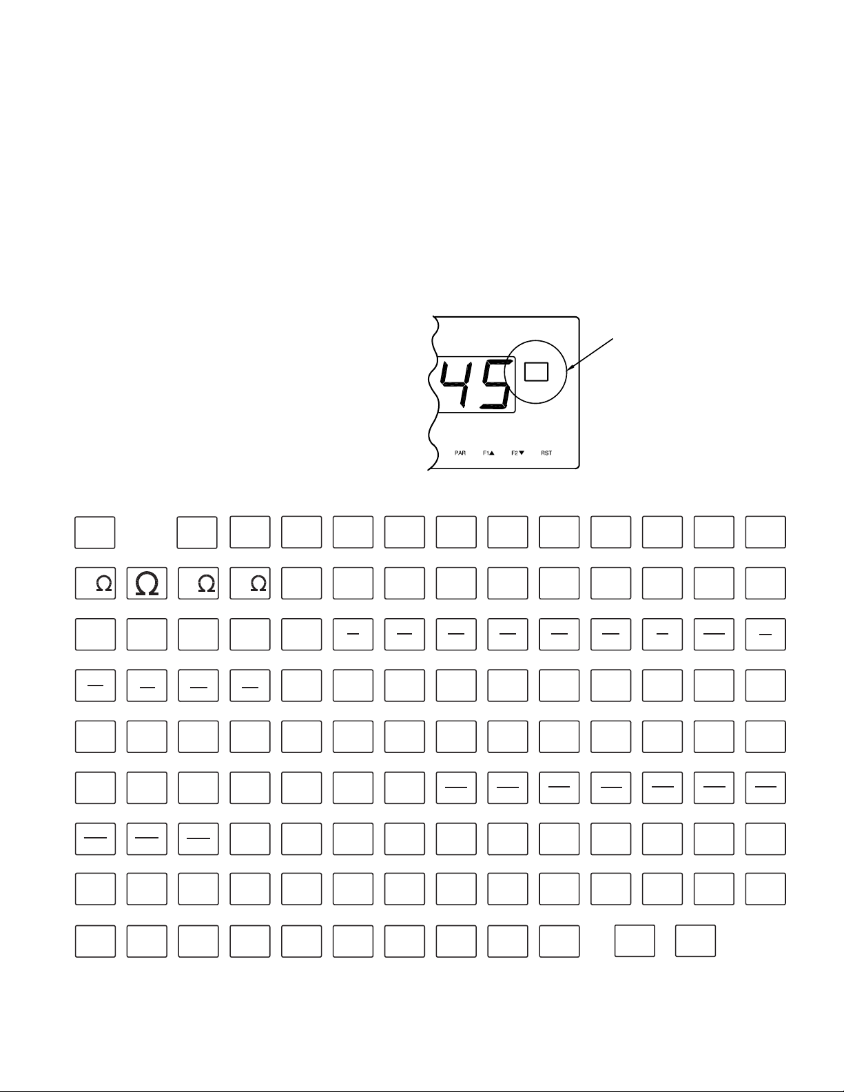
LABEL-LX ACCESSORY
The LX label accessories allow the 5 digit LDP63000 display to be
customized with an engineering unit. The label is affixed to the embossed area
on the bezel of the display. The input module is then programmed to turn on its
backlighting, which illuminates the label from behind. Shown below is a chart
of the preprinted labels available to order.
INSTALLATION
Before applying the label, ensure that the
embossed area is clean, dry, and free of dirt.
Remove the backing and center the label in
the embossed area and attach. Take extra care
to seat the edges of the label.
Attach Units
Label to this
embossed
area.
SP3
SP4
μ
K
LXBLANK0 * LXK00000 LXA00000 LXMA0000 LXUA0000 LXHZ0000 LXKHZ000 LXKV0000 LXVA0000
m
3
cm
ton
h
fps
kph
min min
fpm
RPS
u
K
LXKOHM00 LXMOHM20 LXW00000 LXKW0000 LXKWH000 LXKG0000 LXTON000 LXGAL000 LXL00000 LXML0000 LXKL0000 LXM30000LXMOHM10 LXOHM000
3
inmm
LXIN3000 LXFT3000 LXYD3000 LXL/H000 LXKG/S00 LXKG/MIN LXM3/S00 LXM3/MIN LXM3/H00 LXL/S000 LXL/MIN0 LXKG/H00LXCM3000 LXMM3000
3
ft
s
lb
ft
min
LXFT3/MN LXFT3/H0 LXBPS000 LXBPM000 LXLPM000 LXGPS000 LXGPM100 LXGPM200 LXGPH000 LXFPS100 LXFPM100 LXFPH000LXTON/H0 LXFT3/S0
YPS YPM
LXYPS000 LXYPM000 LXYPH000 LXIPS000 LXIPM000 LXIPH000 LXCPS000 LXCPM000 LXCPH000 LXMPS000 LXMPM000 LXMPH000LXFPS200 LXFPM200
rps
LXRPS200 LXRPM000 LXRPH000 LXPPB000 LXPPM000 LXMM/S00 LXCM/S00 LXCM/MIN LXM/S000 LXM/MIN0 LXM/H000 LXT/MIN0LXKPH000 LXRPS100
lb
h T
LXLB/H00 LXT10000 LXT20000 LX%RH000 LXPH0000 LXDEG000 LXG00000 LXOZ0000 LXLB0000 LX10X000 LX100X00 LX1000X0LXU/MIN0 LXLB/MIN
A
M
3
3
rpm
barØCØBØA
LXPHC000 LXBAR000 LXINHG00 LXPSI000 LXKPA000 LX%00000 LXIN0000 LXFT0000 LXYD0000 LXMM0000 LXCM0000 LXM00000LXPHA000 LXPHB000
km
N
hp
LXHP0000 LXINLB00 LXFTLB00 LXMIN000 LXH00000 LXS00000 LXSEC000 LXVDC000 LXDF0000 ** LXDC0000 **LXKM0000 LXN00000
in lb
mA
W
3
ft
3
ft
h
3
yd
BPS
YPH
rph
t
in
Hg
ft lb
A
KW
l
h
BPM
IPS
ppb
%RH
psi
min
Hz
KWh
LPM
IPM
ppm
pH
kPa
hS
kHz
kg
kg
ss
min
gps
IPH
mm
deg
%
kg
kV
ton
m
GPM
CPS
cm
s
G
in
SEC VDC
VA
gal
3
s
3
m
min
gpm
CPM
cm
min
oz
ft
** These labels included with LDP63000-T units* Blank label included with each LDP63000.
kVA
LXKVA000 LXVAC000 LXMV0000 LXV00000
m
gph
CPH MPS
lb
yd
VAC
ll
m
3
h
FPS
m
mins
x10
mm
°
F
l
s
°
C
mV
K m
l
min
FPM
MPM
mm
h
x100
cm
V
3
l
kg
h
FPH
MPH
t
min
x1000
m
Page 4

4
LDP6-ENC9 NEMA 4/IP65 ENCLOSURE
The LDP6-ENC9 NEMA 4/IP65 enclosure provides a means of mounting
the display in dirty or washdown environments. The enclosure comes with all
the gaskets, hardware (except the mounting screws), and brackets required to
base, ceiling, or wall mount the display. The mounting screws to attach the
brackets to your surface are not provided due to the variety of installation
options available.
Rotate bracket for other
installation choices.
ENCLOSURE ASSEMBLY
1. Before drilling a hole in the enclosure for your wire connector or fitting, ensure
that the location you have chosen allows enough clearance around the input
module.
2. Remove the center section of the gasket provided with the display, and slide it
over the rear of the display and onto the mounting studs.
3. Insert the display into the enclosure as illustrated. Install six #10-32 keps nuts
(supplied with the display) and tighten evenly for uniform gasket compression.
The gasket should be compressed to about 75 to 80% of its original thickness.
Do not overtighten the nuts.
4. Run the wires through the hole that was drilled in the enclosure, and attach them
to the display. Wiring instructions are provided in the appropriate product
bulletin shipped with the input Module.
5. Remove the center section of the rear cover gasket. Apply the gasket to the rear
panel of the enclosure by inserting the screws through the panel and into the
holes in the gasket. Position the panel on the enclosure and start all of the
screws. Alternately tighten each screw to ensure uniform gasket compression.
The gasket should be compressed to about 75 to 80% of its original thickness.
6. To securely mount the enclosure, attach the adjustable mounting brackets to the
enclosure using the washers and screws provided.
7. Secure the mounting brackets to the desired mounting location.
LDP6-SHR SHROUD
The optional shroud enhances the readability of the large display unit in areas
with high intensity overhead light sources. The shroud can be used in
conjunction with any installation (panel mount, enclosure, or mounting
brackets). When properly installed, the shroud will not affect the integrity of a
NEMA 4 installation.
DIMENSIONS In inches (mm)
INSTALLATION
1. Remove the center section of the gasket provided with the display, and slide
it over the rear of the display and onto the mounting studs.
2. Orient the shroud and gasket as shown in the assembly figure, and place it
over the display. The studs of the display should now be protruding through
the rear of the shroud.
3. Follow the remaining installation instructions for panel mounting, bracket
mounting or enclosure mounting as appropriate.
DIMENSIONS In inches (mm)
Page 5

5
LDP6-MB-MOUNTING BRACKETS
The LDP6-MB mounting brackets provide an easy way to base, wall, or
ceiling mount the display. The LDP6-MB kit comes with two sets of brackets,
and most of the hardware to mount the display at virtually any angle. The
screws to attach the brackets to your surface are not provided due to the variety
of installation options available.
Notes:
1. When installing the brackets, the fastener bracket must be installed on the
studs of the display as shown.
2. The mounting bracket may be installed with the flange facing in or out.
3. The rubber washers provided must be installed between the two mounting
brackets during assembly.
4. The screws for fastening the brackets to a surface are not provided in the
LDP6-MB kit. The holes are 0.2" in diameter and will accept size #10 screws
and smaller.
ASSEMBLY
DIMENSIONS In inches (mm)
Page 6

6
Page 7

WARRANTY/DISCLAIMER
OMEGA ENGINEERING, INC. warrants this unit to be free of defects in materials and workmanship for a
period of 13 months from date of purchase. OMEGA’s WARRANTY adds an additional one (1) month grace
period to the normal one (1) year product warranty to cover handling and shipping time. This ensures
that OMEGA’s customers receive maximum coverage on each product.
If the unit malfunctions, it must be returned to the factory for evaluation. OMEGA’s Customer Service
Department will issue an Authorized Return (AR) number immediately upon phone or written request. Upon
examination by OMEGA, if the unit is found to be defective, it will be repaired or replaced at no charge.
OMEGA’s WARRANTY does not apply to defects resulting from any action of the purchaser, including but
not limited to mishandling, improper interfacing, operation outside of design limits, improper repair, or
unauthorized modification. This WARRANTY is VOID if the unit shows evidence of having been tampered
with or shows evidence of having been damaged as a result of excessive corrosion; or current, heat,
moisture or vibration; improper specification; misapplication; misuse or other operating conditions outside
of OMEGA’s control. Components in which wear is not warranted, include but are not limited to contact
points, fuses, and triacs.
OMEGA is pleased to offer suggestions on the use of its various products. However, OMEGA
neither assumes responsibility for any omissions or errors nor assumes liability for any
damages that result from the use of its products in accordance with information provided by
OMEGA, either verbal or written. OMEGA warrants only that the parts manufactured by the
company will be as specified and free of defects. OMEGA MAKES NO OTHER WARRANTIES OR
REPRESENTATIONS OF ANY KIND WHATSOEVER, EXPRESSED OR IMPLIED, EXCEPT THAT OF
TITLE, AND ALL IMPLIED WARRANTIES INCLUDING ANY WARRANTY OF MERCHANTABILITY
AND FITNESS FOR A PARTICULAR PURPOSE ARE HEREBY DISCLAIMED. LIMITATION OF
LIABILITY: The remedies of purchaser set forth herein are exclusive, and the total liability of
OMEGA with respect to this order, whether based on contract, warranty, negligence,
indemnification, strict liability or otherwise, shall not exceed the purchase price of the
component upon which liability is based. In no event shall OMEGA be liable for consequential,
incidental or special damages.
CONDITIONS: Equipment sold by OMEGA is not intended to be used, nor shall it be used: (1) as a “Basic
Component” under 10 CFR 21 (NRC), used in or with any nuclear installation or activity; or (2) in medical
applications or used on humans. Should any Product(s) be used in or with any nuclear installation or activity,
medical application, used on humans, or misused in any way, OMEGA assumes no responsibility as set forth
in our basic WARRANTY/DISCLAIMER language, and, additionally, purchaser will indemnify OMEGA and
hold OMEGA harmless from any liability or damage whatsoever arising out of the use of the Product(s) in
such a manner.
RETURN REQUESTS/INQUIRIES
Direct all warranty and repair requests/inquiries to the OMEGA Customer Service Department. BEFORE
RETURNING ANY PRODUCT(S) TO OMEGA, PURCHASER MUST OBTAIN AN AUTHORIZED RETURN (AR)
NUMBER FROM OMEGA’S CUSTOMER SERVICE DEPARTMENT (IN ORDER TO AVOID PROCESSING
DELAYS). The assigned AR number should then be marked on the outside of the return package and on any
correspondence.
The purchaser is responsible for shipping charges, freight, insurance and proper packaging to prevent
breakage in transit.
OMEGA’s policy is to make running changes, not model changes, whenever an improvement is possible. This affords our
customers the latest in technology and engineering.
OMEGA is a registered trademark of OMEGA ENGINEERING, INC.
© Copyright 2006 OMEGA ENGINEERING, INC. All rights reserved. This document may not be copied, photocopied,
reproduced, translated, or reduced to any electronic medium or machine-readable form, in whole or in part, without the
prior written consent of OMEGA ENGINEERING, INC.
FOR WARRANTY RETURNS, please have the
following information available BEFORE
contacting OMEGA:
1. Purchase Order number under which the product
was PURCHASED,
2. Model and serial number of the product under
warranty, and
3. Repair instructions and/or specific problems
relative to the product.
FOR NON-
WARRANTY REPAIRS, consult OMEGA
for current repair charges. Have the following
information available BEFORE contacting OMEGA:
1. Purchase Order number to cover the COST of the
repair,
2. Model and serial number of the product, and
3. Repair instructions and/or specific problems
relative to the product.
Page 8

Where Do I Find Everything I Need for
Process Measurement and Control?
OMEGA…Of Course!
Shop online at omega.com
TEMPERATURE
] Thermocouple, RTD & Thermistor Probes, Connectors, Panels & Assemblies
] Wire: Thermocouple, RTD & Thermistor
] Calibrators & Ice Point References
] Recorders, Controllers & Process Monitors
] Infrared Pyrometers
PRESSURE, STRAIN AND FORCE
] Transducers & Strain Gages
] Load Cells & Pressure Gages
] Displacement Transducers
] Instrumentation & Accessories
FLOW/LEVEL
] Rotameters, Gas Mass Flowmeters & Flow Computers
] Air Velocity Indicators
] Turbine/Paddlewheel Systems
] Totalizers & Batch Controllers
pH/CONDUCTIVITY
] pH Electrodes, Testers & Accessories
] Benchtop/Laboratory Meters
] Controllers, Calibrators, Simulators & Pumps
] Industrial pH & Conductivity Equipment
DATA ACQUISITION
] Data Acquisition & Engineering Software
] Communications-Based Acquisition Systems
] Plug-in Cards for Apple, IBM & Compatibles
] Datalogging Systems
] Recorders, Printers & Plotters
HEATERS
] Heating Cable
] Cartridge & Strip Heaters
] Immersion & Band Heaters
] Flexible Heaters
] Laboratory Heaters
ENVIRONMENTAL
MONITORING AND CONTROL
] Metering & Control Instrumentation
] Refractometers
] Pumps & Tubing
] Air, Soil & Water Monitors
] Industrial Water & Wastewater Treatment
] pH, Conductivity & Dissolved Oxygen Instruments
M4531/0607
 Loading...