

Omega Products iSE-TH Installation Manual

User’s Guide
®
®
Shop on line at
omega.com
e-mail: info@omega.com
For Latest Product Manuals
omegamanual.info
Temperature + Humidity
Environmental Surveillance over the Internet

It is the policy of OMEGA to comply with all worldwide safety and EMC/EMI regulations that apply.
OMEGA is constantly pursuing certification of its products to the European New Approach Directives. OMEGA will add the CE mark
to every appropriate device upon certification.
The information contained in this document is believed to be correct, but OMEGA Engineering, Inc. accepts no liability for any
errors it contains, and reserves the right to alter specifications without notice.
WARNING: These products are not designed for use in, and should not be used for, patient-connected applications.
This device is marked with the international caution symbol. It is important to read the Setup Guide before installing or
commissioning this device as the guide contains important information relating to safety and EMC.

Part 1: Introduction
Part 2: Hardware
Part 3: Network Configuration
Part 4: Operations
Part 5: Specifications ..........................................................................................................45
Part 6: Factory Preset Values ...................................................................................................47
Appendix A Glossary ..........................................................................................................48
Appendix B IP Address ......................................................................................................49
Appendix C IP Netmask ......................................................................................................50
1.1 Safety and EMC Considerations .....................................................................2
1.2 Before You Begin .............................................................................................2
1.3 Description........................................................................................................2
2.1 Wall Mounting ..................................................................................................5
2.2 DIP Switch Location.........................................................................................6
2.3 Parts of the iSE Unit ........................................................................................7
2.4 Disassembly Instruction .................................................................................8
2.5 Network Communication Interfaces ..............................................................9
2.5.1 10Base-T RJ-45 Pinout ......................................................................9
2.5.2 10Base-T Crossover Wiring ..............................................................9
2.6 Relay and I/O Contact Wiring Connections ..................................................9
2.7 DC Power Input Wiring Connections..............................................................9
2.8 Running on Battery Power ...........................................................................10
2.9 Flash Memory Format ...................................................................................11
3.1 Network Protocols .........................................................................................12
3.2 Ethernet (MAC) Address ...............................................................................12
3.3 DHCP ..........................................................................................................13
3.4 DNS ..........................................................................................................13
3.5 IP Address ......................................................................................................13
3.5.1 Default IP Address ...........................................................................14
3.6 Port Number....................................................................................................14
4.0 Testing the Connection .................................................................................15
4.1 iConnect Software..........................................................................................16
4.2 Setting a new IP Address over the Network ...............................................18
4.3 Setup and Operation using the iSE Web Page ...........................................19
4.3.1 Read Sensor .....................................................................................20
4.3.1.1 Java Runtime Environment 1.4 Setup Instructions ..........20
4.3.1.2 Java Runtime Environment 1.5 (5.0) Setup Instructions ..21
4.3.1.3 Browser Proxy Selection......................................................21
4.3.2 Adjustable Chart...............................................................................22
4.3.3 Retrieving Data from Flash..............................................................23
4.3.4 Access Control ................................................................................24
4.3.5 Configuration....................................................................................25
4.3.5.1 Configuration - Recording Initializing ................................31
4.3.5.2 Configuration - Recording Active .......................................32
4.3.5.3 Important Recording Notes .................................................33
4.3.6 Sensor Parameters.........................................................................................34
4.4 Telnet Setup ...................................................................................................35
4.5 HTTPget Program...........................................................................................36
4.5.1 HTTPget using Port 1000.................................................................36
4.5.2 HTTPget and ARP to setup Device IP Address ............................38
4.6 ARP Protocol ..................................................................................................39
4.7 iLog Software..................................................................................................40
4.8 Mail Notifier Software.....................................................................................42
4.8.1 Installation ........................................................................................42
4.8.2 Program Options Setup and Configuration ..................................43
4.8.3 Device Setting Setup and Configuration........................................44
i
TABLE OF CONTENTS

Appendix D ASCII Chart ....................................................................................................51
Appendix E iLog Error Messages......................................................................................53
Part 7: Approvals Information ...................................................................................................54
7.1 Electromagnetic Compatibility (EMC) ............................................................54
7.2 FCC ..............................................................................................................54
ASCII Chart Control Codes ...........................................................................52
LIST OF FIGURES:
Figure 1.1 iSE and iLD Big Display on the Ethernet Network ..............................4
Figure 2.1 Mounting ................................................................................................5
Figure 2.2 Dimensions ............................................................................................5
Figure 2.3 DIP Switch Location...............................................................................6
Figure 2.4 Parts of the iSE Unit...............................................................................7
Figure 2.5 Opening the Unit ....................................................................................8
Figure 2.6 RJ45 Pinout ............................................................................................9
Figure 2.7 10Base-T Crossover Cable Wiring .......................................................9
Figure 2.8 Relay and I/O Contact Connections ....................................................9
Figure 2.9 Battery and S5 Jumper Location .......................................................10
Figure 2.10 Chart of Simulated Data.......................................................................11
Figure 3.1 Labeling ................................................................................................12
Figure 3.2 DIP Switch on the Bottom Side of iSE................................................13
Figure 3.3 Telnet Login into the iSE .....................................................................14
Figure 4.1 Pinging the iSE from MS-DOS Prompt ..............................................15
Figure 4.2 Assigning an IP Address using iConnect .........................................16
Figure 4.3 Accessing the iSE’s Home Page Menu ..............................................17
Figure 4.4 Access Control ...................................................................................18
Figure 4.5 iSE Home Page ....................................................................................19
Figure 4.6 LOGIN and ADMINISTRATOR Passwords ........................................19
Figure 4.7 Read Sensor .........................................................................................20
Figure 4.8 Adjustable Chart...................................................................................22
Figure 4.9 iFlash Download Utility........................................................................23
Figure 4.10 Access Control ....................................................................................24
Figure 4.11 Configuration ......................................................................................26
Figure 4.12 Configuration - Flash Recording Settings ........................................30
Figure 4.13 Configuration (Recording Initializing) ...............................................31
Figure 4.14 Configuration (Recording Active) ......................................................32
Figure 4.15 Sensor Parameters - Temperature .....................................................34
Figure 4.13 Sensor Parameters - Input Contact ...................................................34
Figure 4.14 Remote End Char .................................................................................35
Figure 4.15 ARP Commands and Responses .......................................................39
Figure 4.16 iLog Software Logging Data................................................................40
Figure 4.17 iSE Mail Notifier Main Window ............................................................41
Figure 4.18 iSE Mail Notifier Profile Setup.............................................................42
Figure 4.19 iSE Mail Notifier Device Setting .........................................................43
LIST OF TABLES:
Table 2.1 Parts of iSE Unit.....................................................................................7
Table 4.1 iLog Excel Applications ......................................................................41
ii
NOTES, WARNINGS and CAUTIONS
Information that is especially important to note is identified by the following labels:
• NOTE
• WARNING or CAUTION
• IMPORTANT
• TIP
NOTE: Provides you with information that is important to successfully
setup and use the iSE.
CAUTION: Tells you about the risk of electrical shock.
CAUTION: Risk of danger. Tells you of circumstances or practices
that can effect the instrument’s functionality and must refer to
accompanying documents.
TIP: Provides you helpful hints.
FEATURES
• Temperature
• Relative Humidity
• Web Server
• Virtual Chart Recorder
• Two Relay Alarms
• Two Contact Closures
• Accurate Readings
• Password Protection
• Email Alarms
• Data Logging
• 2, 4 or 8M bytes Flash Memory Card
• Real-Time Clock
• LCD Display
• UPS / Stand-alone 9Vdc Battery
1

PART 1
INTRODUCTION
1.1 Safety and EMC Considerations
Refer to the CE Approvals Section.
Warning: The standard right angle probe is ESD Sensitive
EMC Considerations
• Whenever EMC is an issue, always use shielded cables.
• Never run signal and power wires in the same conduit.
• Use twisted-pair wires for signal connections.
• Install Ferrite Bead(s) on signal wires close to the instrument if EMC problems persist.
Failure to follow all instructions and warnings may result in injury!
1.2 Before You Begin
Inspecting Your Shipment: Remove the packing slip and verify that you have received
everything listed. Inspect the container and equipment for signs of damage as soon as
you receive the shipment. Note any evidence of rough handling in transit. Immediately
report any damage to the shipping agent. The carrier will not honor damage claims
unless all shipping material is saved for inspection. After examining and removing the
contents, save the packing material and carton in the event reshipment is necessary.
Customer Service: If you need assistance, please contact the Customer Service
Department nearest you.
Manuals, Software: The latest Operation Manual as well as free configuration software
(iConnect), datalogging software (iLog),
memory card retrieval software (iFlash) and Mail
Notifier are available at the website listed on the cover page of this manual or on the
CD-ROM enclosed with your shipment.
1.3 Description
Web-based Remote Surveillance of Temperature + Humidity and Security
The iSE environmental monitor provides Web-based remote surveillance of
environmental conditions in critical HVAC applications such as computer server rooms,
clean rooms, laboratories, museums, warehouses, or any remote facility. View and
record Temperature, Relative Humidity and Dew Point over an Ethernet network or the
Internet with no special software—just a Web browser.
EMAIL ALARMS -- The device can trigger an alarm if temperature or humidity goes
above or below a set point that you determine. Your alarm can be sent by email to a
single user or to a group distribution list, including text messages to cell phones and
PDA’s.
PHYSICAL THREATS -- The iSE includes screw terminals for two contact closures that
work with common alarm sensors. You can instruct the iSE monitor to send an alarm if a
door is opened, a window is broken, or a fire sprinkler goes off.
POWER FAILURE -- The iSE monitor can trigger an alarm if the AC power fails. The
iSE monitor will continue to collect data for ten days powered by a standard 9 Volt
alkaline battery (included). The data is stored in nonvolatile flash memory and can later
be downloaded over the Ethernet.
2

LOCAL ALARMS -- The iSE monitor includes two 1.5 Amp output relays that are
controlled by the alarm conditions you select. The relays can trigger flashing lights and
a siren for example to alert personnel near the scene.
With the easy Web-based setup page, the two relays can be programmed for any
combination of temperature or humidity, and high or low set points, as well as alarm
conditions triggered by contact closures. The relays can also be programmed to turn off
when conditions return to normal, or programmed to remain latched and require a
manual reset.
VIEW CHARTS AND GRAPHS ON THE WEB -- The iSE serves Active Web Pages to
display real time readings, display charts of temperature and humidity, or log data in
standard data formats for use in a spreadsheet or data acquisition program such as
Excel or Visual Basic.
The virtual chart viewed on the web page is a JAVA™ Applet that records a chart over
the LAN or Internet in real time. With the iSE, there is no need to invest time and money
learning a proprietary software program to log or chart the data.
Chart scales are fully adjustable on the fly. For example, the chart can display one
minute, one hour, one day, one week, one month or one year. Temperature and humidity
can be charted across the full span (-40 to 124°C, and 0 to 100% RH) or within any
narrow range such as (20 to 30°C).
LINK TO WEB CAM OR IP CAMERA -- The Web page includes a link to a “Web Cam”
or “IP camera” (not included). If you get a message about an alarm condition, you can
quickly click on the link to view the actual scene over the Internet.
FLASH MEMORY -- The iSE records data on a removable 2-MByte Flash Memory card
(included) that can store one full year of readings taken at one-minute intervals (or two
months of readings taken at ten second intervals).
Up to four years of temperature + humidity readings can be stored on the optional 8
MByte card. Even if the Ethernet network fails, data will continuously record on the builtin nonvolatile flash memory.
The iSE monitors come complete with a plug-in temperature and humidity probe that
mounts on the instrument or separately with the six foot extension cable (included).
The temperature/ humidity sensors are interchangeable and do not require routine
calibration. And if a replacement sensor is ever needed, the instrument does not require
calibration.
Installation and operation of the iSE monitor requires no special training, tools, or
software. The device connects to any Ethernet network with standard cable and is
powered by a universal AC adapter which is supplied with the product.
AWARD-WINNING TECHNOLOGY -- The iSE is simple to install and use, and features
award-winning iServer technology that requires no special software except a Web
Browser.
The iSE connects to an Ethernet Network with a standard RJ45 connector and sends
data in standard TCP/IP packets. It is easily configured with a simple menu using a Web
Browser and can be password protected. From within an Ethernet LAN or over the
Internet, the user simply types its IP address or an easy to remember name such as
"Cleanroom 5" or "Server Room" in any Web Browser, and the iSE serves a Web Page
with the current readings.
3
TYPICAL APPLICATIONS -- The iSE is great for monitoring and recording temperature
+ humidity in applications such as: clean rooms, computer rooms, HVAC systems,
pharmaceutical and food processing and storage, hospitals, laboratories, semiconductor
fabs, electronic assembly, warehousing, museums, manufacturing, greenhouses, farm
animal shelters, and many more.
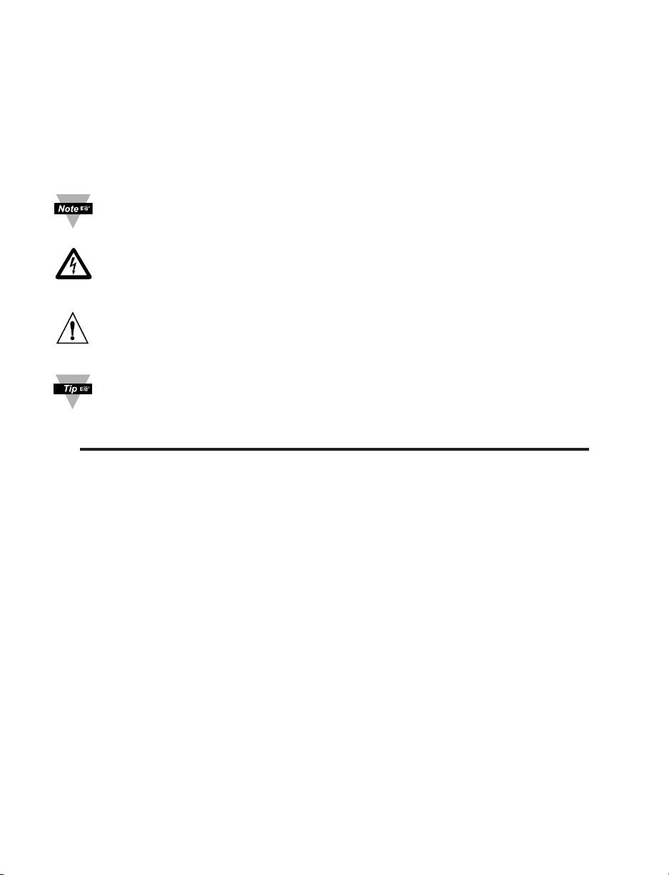
The following example illustrates how you can hookup an iSE, a network display (iLD),
and a network camera to your network:
Figure 1.1 iSE and iLD Big Display on the Ethernet Network
4
PART 2 HARDWARE
3.25 [82.6]
2.55 [64.8]
3.47 [88.1]
1.31
[33.3]
0.10
[2.54]
1.00 [25.4] 5.13 [130.2]
DIAGNOSTICS
NETWORK LINK
ACTIVITY
C/ F TIME BKLT
TEMPERATURE/HUMIDITY
0.59 [14.9]
1.81 [46.1]
1.50 [38.1]
5.13 [130.2]
1.50 [38.1]
0.24 [6.1]
0.94 [23.8]
3.47 [88.1]
1.36 [34.4]
REAR WIRE
ENTRY AREA
ADDITIONAL MOUNTING OPTIONTO RETAIN UNIT TO MOUNTING BRACKET
USE #4 X 1/4" LONG SELF-TAPPING SCREW
DRILL 0.125 [3.17]
USE TWO, #4
FLAT HEAD SCREWS
TO MOUNT BRACKET
UNIT OUTLINE
CLIPS (3)
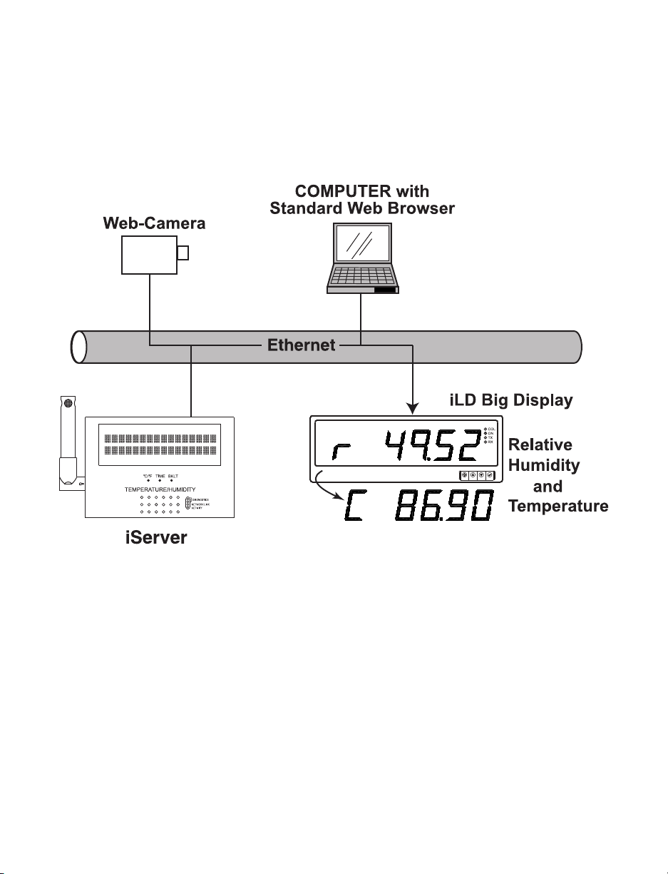
2.1 Wall Mounting
Position unit where required. Mark and drill the two #4 screw holes.
After bracket is mounted on the wall, align back of unit over the three bracket clips, once
engaged, slide downward, the unit will snap in place.
For extra security, you may screw the unit onto the bracket. Remove cover (see Section
2.4) and screw a #4 x 1/4” long self-tapping screw through the case and bracket.
It is recommended that
you ground your
unit by wrapping a wire
around the case’s
bottom screw or
by
connecting a wire to
the Return/Ground
position of the relay
connector (see Figure
2.8 and 3.1).
Figure 2.1 Mounting
Figure 2.2 Dimensions
5

2.2 DIP Switches
The iSE is shipped with all DIP switches in "OFF" position.
DIP Switch Usage
1) N/C - not used
2) To change to default factory settings
3) To enable/disable DHCP
4) N/C - not used
Figure 2.3 DIP Switch Location
To set the iSE to factory default settings, slide DIP switch #2 to ON position.
Power the iSE on and wait about 10 seconds until the iSE fully boots up.
Set the DIP switch #2 back to OFF position (it does not matter if the iSE is powered ON
or OFF, just make sure that the DIP switch is set to OFF, otherwise, every time the unit
is power-cycled the factory settings will take over.
6
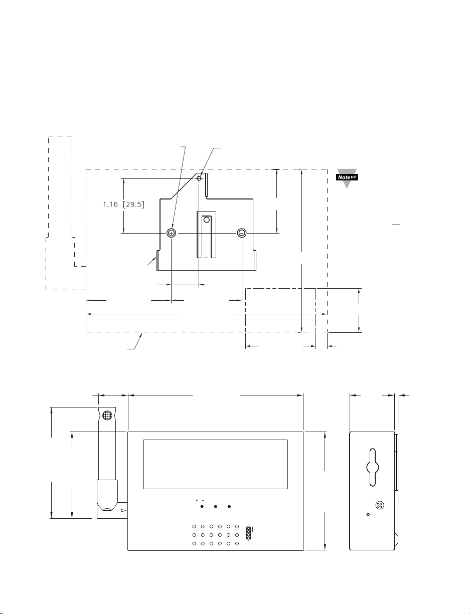
2.3 Parts of the iSE Unit
DIAGNOSTICS
NETWORK LINK
ACTIVITY
C/ F TIME BKLT
TEMPERATURE/HUMIDITY
RST
ETHERNET
9-12 Vdc
dc Power Input
Flash
Memory
Card
Reset
Button
Cover
Screw
(2 plcs)
Flash
Memory
Card
32 Digit LCD Display
Buttons
RJ45 interface
1
8
iServer
Reset Button
Detachable
Temp + RH
Probe
Battery
(inside cover)
iServer LEDs
Bottom Wire Entry
I/O Connectors
Removable Plug
Connector for
Input and Outputs
(inside cover)
1
614
S5 Jumper
(inside cover)
TOP VIEW
+-
Warning:
The standard
right angle
probe is ESD
Sensitive
Figure 2.4 Parts of the iSE Unit
Table 2.1 Parts of iSE Unit
ETHERNET RJ45 interface for 10BASE-T connection.
RESET Button: Used for power reseting the iSE.
ACTIVITY LED (Red) Blinking: Indicates network activities (receiving or sending packets).
NET LINK LED (Green) Solid: Indicates good network link.
DIAGNOSTICS LED (Yellow) Blinking: Indicates transmitting data from iSE to flash memory
card. When DHCP enabled, it remains solid until DHCP IP address is received.
°C/°F
LED (Green) Blinking: Indicates receiving data by the iSE from flash memory.
Button: Change display units of measurement from °C to °F
TIME Button: Change display from DATE and TIME to RH and TEMP
BKLT Button: Display Back Light
When using the small push buttons, hold the button until “WAIT” is displayed on the LCD and
then release.
7
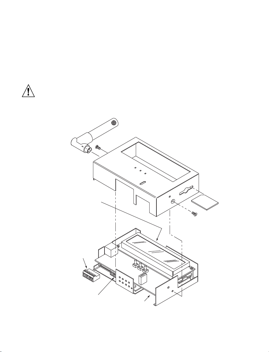
2.4 Disassembly Instruction
MOUNTING
SCREWS (2)
FLASH
CARD
COVER
RELAY
CONNECTOR
TRAY
I/O CONTACT
CONNECTOR
ETHERNET &
DC POWER
CONNECTORS
BATTERY &
S5 JUMPER
LOCATION
TEMP/
HUMIDITY
PROBE
2MB
You will need to open the unit for one of the following reasons:
• To wire relay and I/O contact connectors. (Refer to Section 2.6).
• To connect or replace the battery. (Refer to Section 2.7).
• To change S5 jumper. In the absence of AC power, and if S5 is installed, the LCD
Backlight and iSE Board will be on and running on the battery power. (Refer to
Section 2.7).
Disconnect the power supply before proceeding.
• Make sure the Flash memory Card is fully installed, before removing the cover,
• Remove Probe, then remove cover, by removing 2 screws on each side.
Figure 2.5 Opening the Unit
8
2.5 Network Communication Interfaces
154326
COM1
COM2
9 Vdc
RTN
NO2
NO1
RELAY 2 RELAY 1
1432
IN1
IN2
RTN
OUTPUT
INPUTS
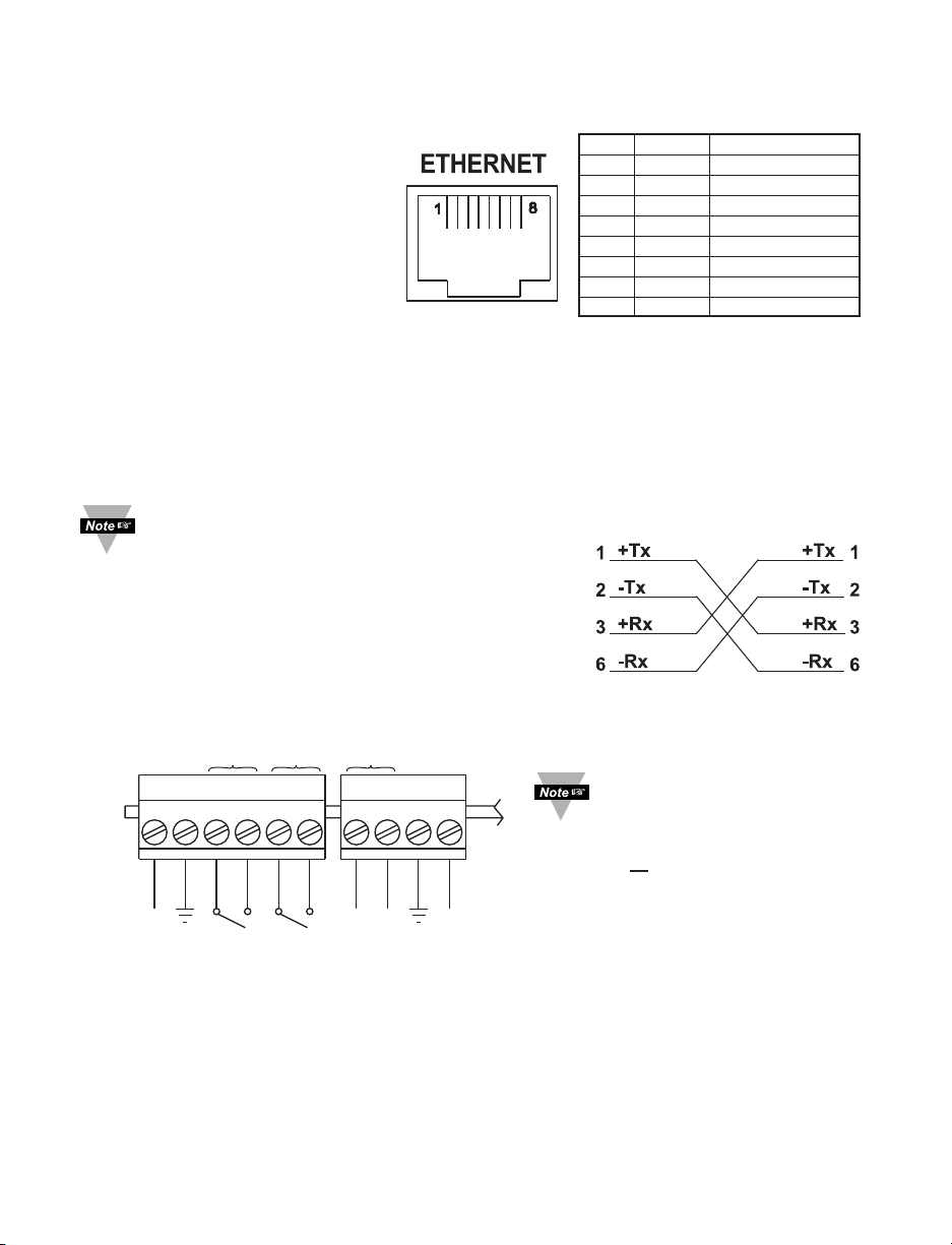
2.5.1 10Base-T RJ-45 Pinout
The 10BASE-T Ethernet network
(RJ45) system is used in the iSE for
network connectivity. The 10 Mbps
twisted-pair Ethernet system
operates over two pairs of wires.
One pair is used for receiving data
signals and the other pair is used
for transmitting data signals. This
means that four pins of the eight-pin
Pin Name Description
1 +Tx + Transmit Data
2 -Tx - Transmit Data
3 +RX + Receive Data
4 N/C Not Connected
5 N/C Not Connected
6 -Rx - Receive Data
7 N/C Not Connected
8 N/C Not Connected
connector are used.
Figure 2.6 RJ45 Pinout
2.5.2 10Base-T Crossover Wiring
When connecting the iSE directly to the computer’s network port, the transmit data pins of the
computer should be wired to the receive data pins of the iSE, and vice versa. The 10Base-T
crossover cable with pin connection assignments are shown below.
Use straight through cable for connecting the iSE to an Ethernet hub. The ports on
the hub are already crossed.
2.6 Relay and I/O Contact Wiring Connections
To access the Relay and I/O Contact Connectors you
must remove the cover, refer to Section 2.4.
Figure 2.7 10Base-T
Crossover Cable Wiring
It is recommended that you
ground your unit by
connecting a wire to the
Ground/Return position of the
connector or
by wrapping a wire
around the case’s bottom screw.
Refer to Figure 3.1 for location.
Figure 2.8 Relay and I/O Contact Connections
2.7 DC Power Input Wiring Connections
A universal ac power adapter with 9 Vdc output is included with your unit. It can be plugged in
at the bottom of unit (See Figure 2.3).
The unit can also be powered on the Relay Connector Pin 1 and Pin 2 (See Figure 2.8).
When using these pins to power the iSE, make sure the power adapter is not used.
9
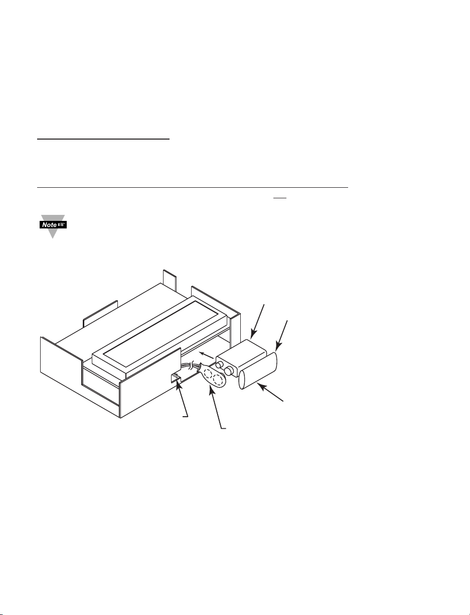
2.8 Running on Battery Power
KEEP INSULATOR COVER
ON BATTERY CLIP
WHEN BATTERY IS NOT
BEING USED
TRAY
REMOVE BATTERY CLIP
INSULA
TOR COVER AND
STORE AGAINST BATTERY
WHEN BATTERY IS BEING USED.
S5 PINS
INSULATOR COVER
9VDC BATTERY
To access the Battery and S5 jumper you must remove the cover, refer to Section 2.4.
When you first connect the battery, without the AC power adapter, the unit will be in “Sleep
Mode”, in order to save power, and the LCD will display “Flash Standby” (provided that S5
jumper is not installed). When battery is installed, plug the AC adapter into unit and push the
Flash Reset Button (refer to Figure 2.4). Unit is now ready to be configured for recording the
data. Also, if the AC adapter is unplugged while the unit is recording, the battery will take
over and recording will continue.
Battery and S5 jumper installed
: if there is a power outage the iSE board will be fully
functional including Ethernet and the LCD backlight “ON”, for approximately 1 hour.
You need to make sure that the LCD/PWR field on the Configuration page of the iSE is set to
UPS (see Section 4.3.5.A)
Battery installed and S5 jumper in storage position (Factory Default of S5)
outage the LCD Backlight and iSE Ethernet will not run, but
the unit will be collecting and
: if there is a power
storing data for approximately 10 days.
If you want to move the unit to a different location, remove the AC adapter; the
installed battery will keep the recording alive until the AC adapter is plugged
back in.
Figure 2.9 Battery and S5 Jumper Location
101011
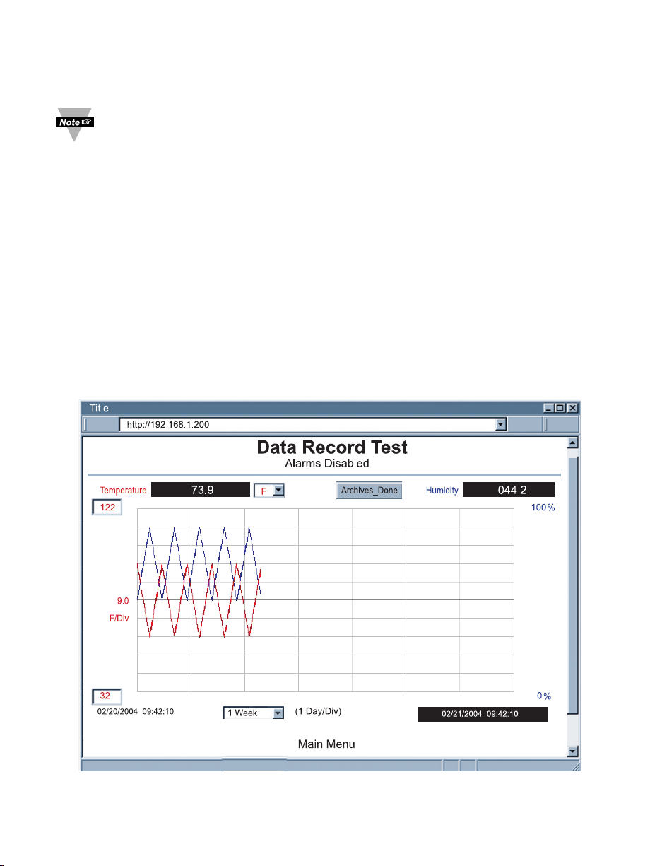
2.9 Flash Memory Format
A 2 Meg flash memory card is included with your product. This memory card is already
formatted; however, the following procedure describes how to format your memory card.
Once the memory card is formatted, all the data that had previously been
recorded will be replaced by simulated test data (see Figure 2.10).
1) Unplug the AC adapter from the unit.
2) Hold down the ºC/ºF button and connect the AC adapter back into the unit.
Release the ºC/ºF button.
3) You will see the following message appear on the LCD: *ºWAITº* *FLASH*.
4) Wait for about 60 seconds and a new message should appear: *OKAY* *FLASH*.
5) Press the ºC/ºF button once and this message will appear: DATA-RECORD-TEST.
6) Press the TIME button and this message will appear: DATA RECORD TEST -
DATA RECORD TEST.
8) Again, press the ºC/ºF button, the firmware version will appear, followed by
*OKAY*.
9) Unplug the AC adapter and plug it back in. The flash memory card is now
formatted. To verify whether the formatting was completed correctly, you should be
able to see the following graph on the WEB server’s “Chart” page.
Figure 2.10 Chart of Simulated Data
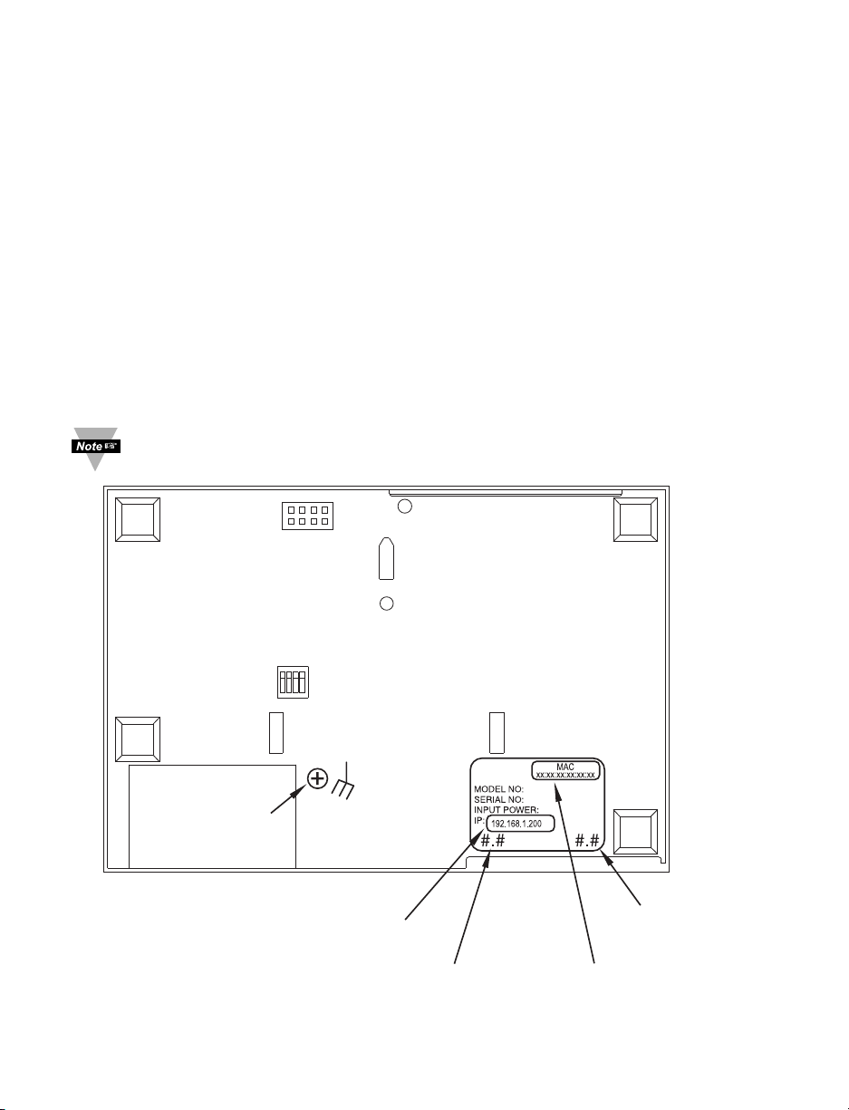
PART 3
MICROPROCESSOR
VERSION #
MAC ADDRESS LABEL
IN HEX CODE
iSE’S VERSION #
REMOVE DEFAULT IP ADDRESS LABEL
AND PUT NEW CUSTOMER'S IP ADDRESS
4 N/C
3 DHCP
2 DEFAULT
1 N/C
OFF
ON
JTAG CONNECTOR
1
SCREW FOR
GROUNDING UNIT
NETWORK CONFIGURATION
3.1 Network Protocols
The iSE can be connected to the network using standard TCP/IP protocols.
It also supports ARP, HTTP (WEB server), DHCP, DNS and Telnet protocols.
3.2 Ethernet (MAC) Address
MAC (Media Access Control) address is your computer's unique hardware number.
When you're connected to the LAN from your computer, a correspondence table relates
your IP address to your computer's physical (MAC) address. The MAC address can be
found on a label attached to your device and contains 6 bytes (12 characters) of
hexadecimal numbers XX:XX:XX:XX:XX:XX hex
For example: 0A:0C:3D:0B:0A:0B
Remove the small label with the default IP address and there will be room to put
your IP address. See Figure 3.1
Figure 3.1 Labeling
12
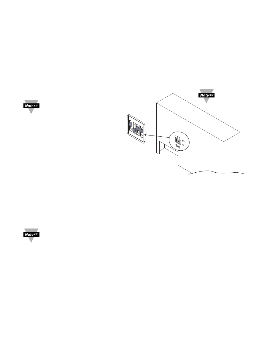
3.3 DHCP
1
4
3
2
OFF
ON
DHCP, Dynamic Host Configuration Protocol enables individual computers or devices to
extract their IP configurations from a server (DHCP server). If the DHCP is enabled on
your iSE, as soon as the iSE is connected to the network, there is an exchange of
information between DHCP server and the iSE. During this process the IP address, the
Gateway address, and the Subnet Mask will be assigned to the iSE by the DHCP server.
Note that the DHCP server must be configured correctly to do such assignment.
If fixed or static IP address is desired, the DHCP must be disabled. The iSE is shipped
with DHCP disabled (factory default). The DHCP can be enabled by setting the DIP
switch #3 to the “ON” position (refer to Figure 3.2).
DIP switch #3
To enable the DHCP,
besides using DIP switch
shown in
“ON” position
#3, set the iSE’s IP
address to 0.0.0.0.
An iSE with IP address of
0.0.0.0 will request an IP
address, gateway
address, and subnet
mask from the DHCP
server over the Ethernet.
3.4 DNS
Figure 3.2 DIP Switch on the Bottom Side of iSE
DNS, Domain Name System enables individual computers and devices to be recognized
over a network based on a specific name instead of an IP address. For example, instead
of having to use http://192.168.1.200 (IP address), you would use only http://eis03ec or
any eight character name stored as Host Name under the Access Control page in the
iSE Home Page. The default DNS name for an iSE is "eis" followed by the last four
digits of the MAC address of that particular iSE.
1. It is very important to communicate with the network administrator in order to
understand the DHCP and its existing configurations on the host server,
before enabling the DHCP on the iSE.
2. The iSE’s are shipped with a default static IP address of 192.168.1.200 and
Subnet Mask of 255.255.255.0.
3. On Windows servers where DHCP and DNS are separate functions it is very
important to configure the DHCP server to communicate with the DNS in
order for the iSE’s Host Name to correctly respond. If you cannot access
the iSE using its Host Name, please contact your network administrator to
make sure the DHCP and DNS servers are linked together.
3.5 IP Address
Every active device connected to the TCP/IP network must have a unique IP address.
This IP address is used to build a connection to the iSE. Every computer using TCP/IP
should have a unique 32-bit address. It is divided into two portions, the network ID and
the host ID. For instance, every computer on the same network uses the same network
ID. At the same time, all of them have a different host ID. For more details about the IP
address see Appendix B.
13
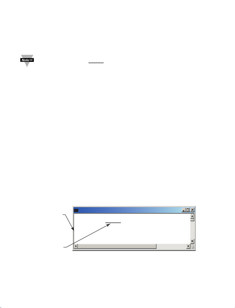
3.5.1 Default IP Address
Firmware Version x.xx
Admin. Password:00000000
Admin. Login Successful
reset
The unit will reset in 5 seconds
_
The default
Admin. Password
Type "reset"
to reboot
the server
C:\
Telnet 192.168.1.200
The iSE is shipped with a default IP address set to 192.168.1.200 and Subnet Mask of
255.255.255.0. If you are going to use a Web browser or Telnet program to access the
iSE using its default IP address, make sure that the PC from which you’re establishing
the connection has an IP address that is in the same range as the iSE’s IP address
(192.168.1.x, where x can be any number from 1 to 254.
Your PC’s IP address cannot
be the same as the iSE’s IP address).
You also need to make sure that your PC’s Subnet Mask is 255.255.255.0. This is a
good way to access the iSE over the network and make any configuration changes
needed. If 192.168.1.200 is already in use on your network, use an Ethernet crossover
cable between your computer and the iSE to change the IP address or any other settings
within the iSE.
3.6 Port Number
All TCP connections are defined by the IP address and a port number. A port number is
an internal address that provides an interface between an application running on your
computer and the network through the TCP/IP protocol.
There are three default TCP socket port numbers assigned to the iSE:
1. Port (socket) number 1000 when using HTTPget program.
2. Port (socket) number 2000 when trying to access the sensor (probe) connected to
the port of the iSE to receive data.
3. Port (socket) number 2002 when trying to access the iSE itself for Power
Recycling the iSE remotely. This can be done using Windows standard Telnet
application.
Power recycling the iSE can also be done through the iSE’s Web Server (see Section 4.2).
Telnet stands for Telecommunications Network, is a protocol that provides a way for
users (or clients) to connect to computers (or servers) on a network, whether in the next
building or across the world.
Example: C:\>Telnet 192.168.1.200 2002
You will then get the following screen.
You can open a Telnet session using other terminal emulation programs like Tera Term
Pro (downloadable from the internet), which is a free software for MS-Windows. It
supports VT100 emulation, Telnet connection and serial com port connections.
Figure 3.3 Telnet Login into the iSE
14
 Loading...