

Page 1
Page 2
Page 3
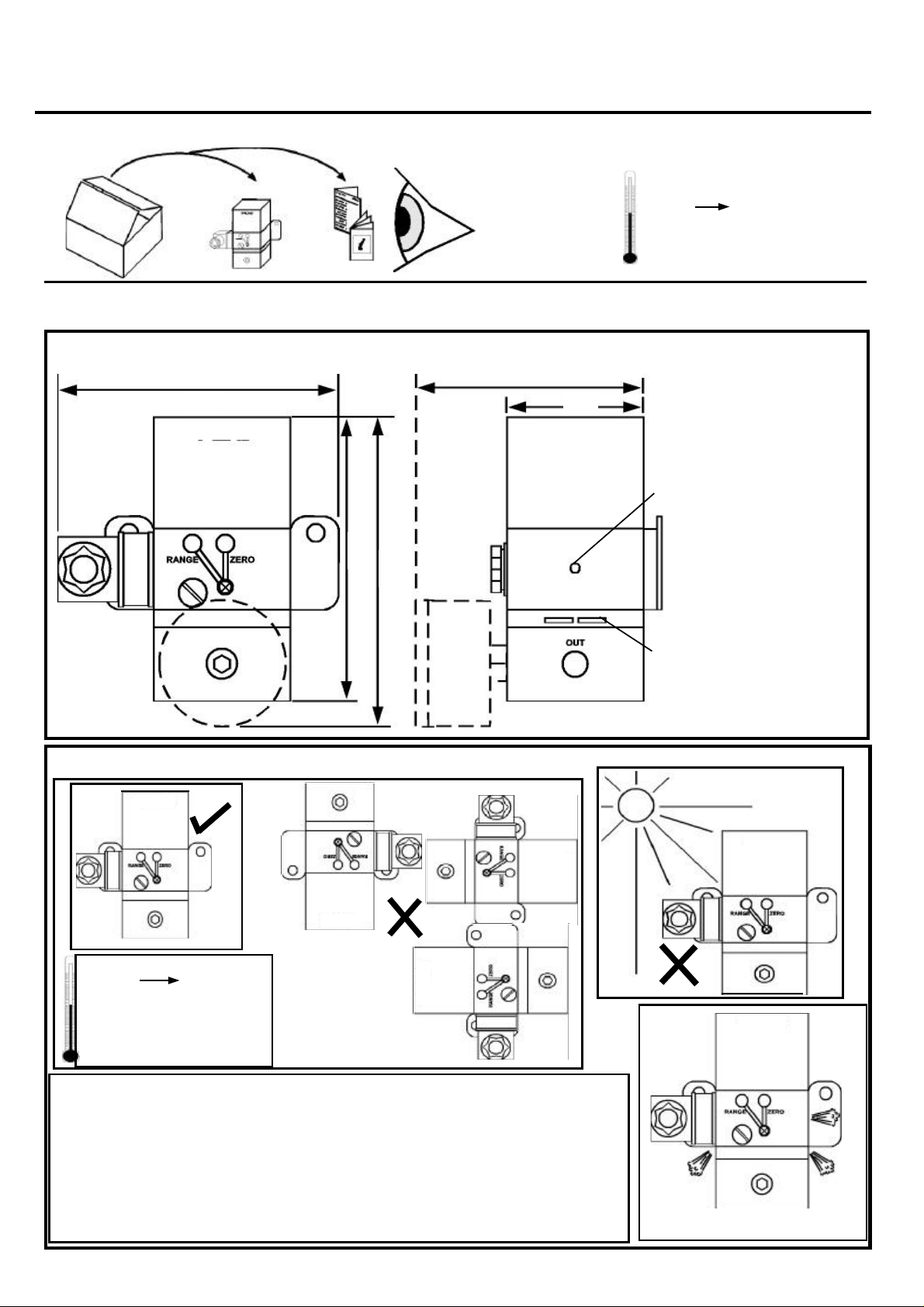
IMPORTANT
STORING
-40ºC +80ºC
INSTALLATION
1. Dimensions in mm
114
Note: Pictures shown as block diagrams: not to scale or diagrammatically
102
54
Bleed vent
102
121
Exhaust vents
2. Requirements
-40ºC +80ºC
Protection IP65 in
operating conditions
Recalibration Required
To conform with the Health and Safety at Work Act 1974 our product should be
installed, used and maintained in accordance with:
1 Normal Safety Procedures
2 The installation and operating instructions provide for each instrument.
3 BS 6379 for general applications or ANSI/ASA-57.3 1975
4 BS 5345 for hazardous area applications
Do not block side vents
Page 4

INSTALLATION (continued)
3. Fixing
a Mounting Bracket
b Pipe Mounting Kit (option)
(i) Remove screws
2 screws
(ii) Remove bracket
(iii) screw in new bracket
(iv) clamp to pipe
(v) Tighten nuts
Ø 50mm nominal
4. Mounting Dimensions
Page 5

5. Make Pneumatic Connections
7. Expose Terminals
b
Soft sealing anaerobic
hydraulic seal
E.g. Loctite hydraulic seal
512
E.g. 6mm (1/4”) nylon
pipe
1/4" NPT OR BSP
c
6. Remove Connector
e
f
d
a
8. Insert Cable
10. Air Supply
BS 6739: 1986
Dust < 5 micron
Oil: < 1ppm mass
Pressure: 1 bar > P2
Cable ø 6 to 8
mm
View Looking at Pins of Instrument
3
-ve
2
1
+ve
Earth
Particle /Water
Removal Filter
Oil/Particle/
Water Removal
Filter
Suitable I/P Converter Up to 6 I/P Converters
Type F72G with 5 micron
Element
Type F72C F74C
9. Assemble and Fit Connector
Type F74G with 5 micron
Element
Dewpoint at least 10ºC below
minimum anticipated ambient
temperature
Regulator Type R72 Type R74
Combination
Filter/Regulator
Type B72 with 5 micron
Element (=F72+R72)
Type B74 with 5 micron
Element
Page 6

11. Calibration
When the instrument is first installed , or after a long period of downtime, a moderate zero shift is normal. This is due
to the rubber diaphragms which are stretched by the internal springs. After a few operations, the instrument will
settle into its normal operating condition. It is recommended that, under these circumstances, instruments should be
exercised by alternately applying zero and full scale signals several times. Zero calibration should then be carried
out.
a.
Air Supply
+ to Maximum Signal
c.
b.
Minimum signal
Adjust zero control (anti-clockwise) to
give minimum required output pressure
Note: Reverse Acting Operation
1 About 20 turns of the zero screw may
be required to reset the zero point.
2 3-wire instruments require to be factory
set for reverse action.
3 Reverse action is not currently
available on high pressure models
4 Do not over wind nozzle to prevent
jamming
Adjust range control (anti-clockwise on 2-wire, clockwise on 3
wire) to give maximum required output pressure
Page 7

12. Maintenance
Care must also be taken to re-align transfer passages correctly during reassembly of the instrument.
Routine maintenance consists of replacing the restrictor screw if the internal orifice becomes blocked.
Parts Breakdown
Page 8

13. Product Variations
3 Wire Versions
These are products designed for electrical control signals which differ from the normal 4-20. 060mA signals. An internal amplifier is fitted to translate the control signal into the required current
through the coil. An external 12V-24V DC signal is required to power the amplifier, which should be
capable of providing 25mA (low pressure) or 65mA. (high pressure)
It is essential that wiring be carried out correctly as incorrect wiring may destroy the amplifier
completely.
Control
3
Common
E-P Versions (Voltage Controlled converters)
These are available in the 2 and 3 wire versions. The two wire versions are recalibrated I/P converters with a suitable buffer resistor in series with the coil to adjust the sensitivity
Captured Exhaust Versions: Designed for use with certain gases. This part must be connected to
a suitable exhaust arrangement e.g. stack pipe. N.B. Check before installation.
Warning: Not for use where no escape of gas is permitted to escape to the environment due to the
constant bleed of the unit
2
3 Wire
1
+
12V –24V
Supply
Common
3
2
2 Wire
1
+
Control
14. Troubleshooting Guide
Problem Posssible Causes Suggested Action
No Output Pressure Reversed Current polarity or
faulty connections
Broken internal wiring
No air supply
Check wiring and signal
continuity with milliameter
Check instrument resistance with
ohmmeter. Repair if faulty.
Correct
Maximum output not available Insufficient supply pressure
Damaged coil or nozzle
Oil contamination
Clogged restrictor
Zero will not adjust Worm disengaged with pinion
(after excessive adjustment)
Zero calibration error on initial
turn-on
Materials of Construction:
Lid: Nylon 66; Magnet: Permanent Neodymium Iron Boron; Magnet Ironwork: Zinc plated mild steel
Flapper: Beryllium Copper; Nozzle: Brass
A small error is normal Exercise instrument several times
Adjust
Return to Factory for Repair
Replace instrument
Replace
Re-engage components
and retest
Page 9

Page 10

M-1438/09/02
 Loading...