

Page 1

SERVER HOME PAGE
http://192.168.1.200
Assembly Dept.
Motion Monitor
CH A: 97574 PPR CH B: 1138 PPR
Message:
a=Quadrature ;b=0;c=95228;d=1138;e=Motion Monitor;f=PPR;g=011;h=200;i=100;j=2;k=0;l=/;m=12:50:03 Nov,22 2003;
a=Quadrature ;b=0;c=96411;d=1138;e=Motion Monitor;f=PPR;g=011;h=200;i=100;j=2;k=0;l=/;m=12:50:03 Nov,22 2003;
a=Quadrature ;b=0;c=97574;d=1138;e=Motion Monitor;f=PPR;g=011;h=200;i=100;j=2;k=0;l=/;m=12:50:03 Nov,22 2003;
Applet pulse started
200 100SP1 SP2
1Minute(1Sec/Div)
Reset Latch A Reset Latch BReset Timer
Mon Nov 24 15:57:43 PST 2003Mon Nov 24 15:24:05 PST 2003
Chart
User’s Guide
Shop on line at
®
®
omega.com
e-mail: info@omega.com
100000-10000
For latest product manuals
omegamanual.info
Internet Counter
Page 2

Page 3

Part 1: Introduction
1.1 Safety and EMC Considerations .......................................................................2
1.2 Before You Begin ................................................................................................2
1.3 Description..........................................................................................................2
Part 2: Hardware
2.1 Mounting ............................................................................................................3
2.1.1 Mounting the Wall Mount iServer ..........................................................3
2.1.2 Mounting the DIN Rail iServer................................................................4
2.1.3 Removal from a DIN Rail ........................................................................4
2.2 DIP Switches .......................................................................................................5
2.2.1 SW1 DIP Switch Usage ...........................................................................5
2.2.2 SW3 DIP Switch Usage ...........................................................................6
2.3 Parts of iServer Unit ..........................................................................................7
2.4 Wiring .................................................................................................................8
2.5 Network Communication Interfaces ................................................................9
2.5.1 10 Base-T RJ-45 Pinout ..........................................................................9
2.5.2 10 Base-T Crossover Wiring ..................................................................9
Part 3: Network Configuration
3.1 Network Protocols ...........................................................................................10
3.2 Ethernet (MAC) Address .................................................................................10
3.3 DHCP ...............................................................................................................11
3.4 DNS ...............................................................................................................11
3.5 IP Address ........................................................................................................12
3.5.1 Default IP Address ................................................................................12
3.6 Port Number......................................................................................................12
Part 4: Operations
4.0 Testing the Connection ....................................................................................13
4.1 iCONNECT Software.........................................................................................14
4.2 Setting a new IP Address over the Network ..................................................15
4.3 Setup and Operation using a Web Browser ..................................................16
4.4 Login ................................................................................................................17
4.5 Java Runtime Environment 1.7 Setup Instructions.......................................17
4.5.1 Browser Proxy Selection........................................................................18
4.6 iServer Operation Basic Menus ......................................................................19
4.6.1 Chart Descriptions .................................................................................19
4.7 Device Configuration Page Items’ Description and Concepts of Setup......
4.7.1 Device Type/Mode Selection ................................................................23
4.7.1.1 Frequency Mode.......................................................................23
4.7.1.2 Totalizer Mode ..........................................................................24
4.7.1.3 Batch Mode...............................................................................26
4.7.1.4 A-B F Mode ...............................................................................28
4.7.1.5 A-B T Mode ...............................................................................30
4.7.1.6 Quadrature Mode ......................................................................32
4.7.1.7 Totalizer Gate Mode ..................................................................34
4.7.2 SetPoint, Alarm and Alarm Output Operation Config ........................36
4.7.2.1 SP1 Value..................................................................................36
4.7.2.2 SP1 Latch Mode .......................................................................36
4.7.2.3 SP1 Active Mode ......................................................................36
4.7.2.4 SP1 Dead Band.........................................................................36
4.7.2.5 SP1 Active Status.....................................................................36
4.7.2.6 SP2 Value..................................................................................37
4.7.2.7 SP2 Latch Mode .......................................................................37
4.7.2.8 SP2 Active Mode ......................................................................37
4.7.2.9 SP2 Dead Band.........................................................................37
4.7.2.10 SP2 Active Status...................................................................37
4.7.3 Title Definability Utility .........................................................................37
TABLE OF CONTENTS
22
i
Page 4

4.7.4 Operation Condition Parameters........................................................38
4.7.4.1 Input Reading Scale & Offset..................................................39
4.7.4.1.1 A Scale ................................................................................39
4.7.4.1.2 A Offset ...............................................................................39
4.7.4.1.3 B Scale ................................................................................39
4.7.4.1.4 B Offset ...............................................................................39
4.7.4.1.5 A Gate Time (ms)................................................................39
4.7.4.1.6 B Gate Time (ms)................................................................39
4.7.4.1.7 A Debounce Time (ms) ......................................................39
4.7.4.1.8 B Debounce Time (ms) ......................................................39
4.7.4.1.9 Reading Format..................................................................40
4.7.4.1.10 Number of Digit ................................................................40
4.7.4.1.11 Decimal Point....................................................................40
4.7.4.2 Counting Mode .........................................................................40
4.7.4.2.1 Combined A-B Mode..........................................................40
4.7.5 Terminal/Remote (Tunneling) Server Setup........................................41
4.8 Telnet Setup .....................................................................................................44
4.8.1 Send Remote Reset ..............................................................................44
4.8.2 Send Commands Manually ..................................................................44
4.8.3 Sending *SRP command for Data Parameter String..........................45
4.8.4 Remote Display Format for Measurement Readings.........................45
4.8.5 A-B Mode ...............................................................................................45
4.9 HTTPGET Program ...........................................................................................46
4.9.1 HTTPGET using Port 1000....................................................................46
4.9.2 HTTPGET and ARP to setup Device IP Address ...............................
4.10 ARP Protocol.....................................................................................................48
4.11 Remote Access (Tunneling).............................................................................49
4.11.1 Local iServer..........................................................................................50
4.11.2 Remote iServer......................................................................................51
4.12 Access Control Descriptions and Functions.................................................52
4.13 iLOG Software...................................................................................................53
4.14 Mail Notifier Software.......................................................................................54
4.14.1 Installation .............................................................................................54
4.14.2 Program Options Setup and Configuration .......................................55
4.14.3 Device Setting Setup and Configuration ............................................56
Part 5: Specifications ............................................................................................................ 56
Part 6: Factory Preset Values ......................................................................................................58
Appendix A Glossary ............................................................................................................59
Appendix B IP Address ........................................................................................................60
Appendix C IP Netmask ........................................................................................................61
Appendix D ASCII Chart .......................................................................................................62
ASCII Chart Control Codes .............................................................................63
Appendix E iLog Error Messages .......................................................................................65
Part 7: Approvals Informatio
7.1 Electromagnetic Compatibility (EMC) ............................................................66
7.2 FCC ..............................................................................................................66
4.7.4.2.2 Counter Mode .....................................................................40
4.7.5.1 TCP/UDP ...................................................................................41
4.7.5.2 Server Type...............................................................................41
4.7.5.3 Number of Connections ..........................................................41
4.7.5.4 Port ............................................................................................42
4.7.5.5 Remote Access ........................................................................42
4.7.5.6 Remote Port..............................................................................42
4.7.5.7 Remote IP Address ..................................................................42
4.7.5.8 List of Available Communication Commands .......................43
47
4.14.2.1 Sending Email Messages to a Cell Phone ...........................55
ii
Page 5

LIST OF FIGURES:
Figure 2.1 Mounting - Wall Mount iServer ..........................................................................3
Figure 2.2 Mounting - DIN Rail iServer ...............................................................................4
Figure 2.3 Removal - DIN Rail iServer ................................................................................4
Figure 2.4a DIP Switch SW1 - Wall Mount iServer ...............................................................5
Figure 2.4b DIP Switch SW1 - DIN Rail iServer....................................................................5
Figure 2.5a DIP Switch SW3 - Wall Mount iServer ...............................................................6
Figure 2.5b DIP Switch SW3 - DIN Rail iServer....................................................................6
Figure 2.6 Parts of iServer Unit............................................................................................7
Figure 2.7a Wall Mount iServer 8 Position Connector.........................................................8
Figure 2.7b DIN Rail iServer 8 Position Connector ..............................................................8
Figure 2.8 RJ45 Pinout ........................................................................................................9
Figure 2.9 10Base-T Crossover Cable Wiring ...................................................................9
Figure 3.1 Labeling ............................................................................................................10
Figure 3.2 DIP Switch SW1 ................................................................................................11
Figure 4.1 Pinging the iServer from MS-DOS Prompt ....................................................13
Figure 4.2 Assigning an IP Address using iCONNECT ..................................................14
Figure 4.3 Accessing the iServer’s Home Page ...............................................................14
Figure 4.4 Access Control ................................................................................................15
Figure 4.5 iServer Home Page Menu ................................................................................16
Figure 4.6 Login Password ...............................................................................................17
Figure 4.7 Java 1.7.x Screen Shot .....................................................................................17
Figure 4.8 Chart Descriptions ............................................................................................19
Figure 4.9 Configuration/Device Setup ............................................................................22
Figure 4.10 Example of Totalizer Mode ...............................................................................25
Figure 4.11 Example of Batch Mode ...................................................................................27
Figure 4.12 Example of A-B F Mode ....................................................................................29
Figure 4.13 Example of A-B T Mode with Bar Chart...........................................................31
Figure 4.14 Example of Quadrature Mode ..........................................................................33
Figure 4.15 Example of Totalizer Gate Mode ......................................................................35
Figure 4.16 Example of SetPoint / Alarm Configuration ...................................................36
Figure 4.17 Example of Title Definability Utility ...............................................................37
Figure 4.18 Example of Operation Condition Parameters ................................................38
Figure 4.19 Terminal / Remote (Tunneling) Server Setup..................................................41
Figure 4.20 Telnet Login into the iServer ............................................................................44
Figure 4.21 Response of Command *SRP inquiry Using Terminal Setup........................45
Figure 4.22 Dual Frequency Counter in A-B (+) Mode is Displayed Under
Figure 4.23 Example of Using Httpget Program.................................................................47
Figure 4.24 ARP Commands and Responses ...................................................................49
Figure 4.25 Device-to-Device Communication ...................................................................49
Figure 4.26 Local iServer Config. Terminal Server/Remote Access.................................50
Figure 4.27 Remote iServer Config. Terminal Server/Remote Access.............................51
Figure 4.28 Access Control .................................................................................................52
Figure 4.29 iLOG Software Logging Data ...........................................................................53
Figure 4.30 iServer Mail Notifier Main Window ..................................................................54
Figure 4.31 iServer Mail Notifier Profile Setup ..................................................................55
Figure 4.32 iServer Mail Notifier Device Setting ................................................................56
Continuous Mode Using Remote Terminal Server.........................................45
LIST OF TABLES:
Table 2.1 Parts of iServer Unit............................................................................................7
Table 4.1 Message Item Window Description .................................................................21
iii
Page 6

Table 4.2 List of Communication Commands ................................................................43
iv
Page 7
NOTES, WARNINGS and CAUTIONS
Information that is especially important to note is identified by the following labels:
• NOTE
• WARNING or CAUTION
• IMPORTANT
• TIP
NOTE: Provides you with information that is important to successfully
setup and use the iServer.
CAUTION: Tells you about the risk of electrical shock.
CAUTION: Risk of danger. Tells you of circumstances or practices
that can effect the instrument’s functionality and must refer to
accompanying documents.
TIP: Provides you helpful hints.
FEATURES
• Displays Rate, Frequency, Pulse, Total, Batch, and
Quadrature over Ethernet and Internet
• Web based interface
• No special software needed
• Up to 500 KHz input
• Chart, Bar Graph, and X/Y displays
•
2 Channel input/output
• Custom firmware and private labeling for OEM’s
1
Page 8

PART 1
INTRODUCTION
1.1 Safety and EMC Considerations
Refer to the CE Approvals Section. Always use a power supply, which complies with EN
60950 safety standard.
EMC Considerations
• Whenever EMC is an issue, always use shielded cables.
• Never run signal and power wires in the same conduit.
• Use twisted-pair wires for signal connections.
• Install Ferrite Bead(s) on signal wires close to the instrument if EMC problems persist.
Failure to follow all instructions and warnings may result in injury!
1.2 Before You Begin
Inspecting Your Shipment: Remove the packing slip and verify that you have received
everything listed. Inspect the container and equipment for signs of damage as soon as
you receive the shipment. Note any evidence of rough handling in transit. Immediately
report any damage to the shipping agent. The carrier will not honor damage claims
unless all shipping material is saved for inspection. After examining and removing the
contents, save the packing material and carton in the event reshipment is necessary.
Customer Service: If you need assistance, please contact the Customer Service
Department nearest you.
Manuals, Software: The latest Operation Manual as well as free software and iServer
Mail Notifier are available at the website listed on the cover page of this manual or
on the CD-ROM enclosed with your shipment.
1.3 Description
The iServer Internet Counter puts “dumb” data on the World Wide Web. This revolutionary
technology transmits virtually any conventional counting application up to 500 KHz over an
Ethernet network or the Internet.
This iServer can count contacts from the simplest button or switch, as well as count
pulses from most any conventional transducer such as a proximity sensor or quadrature
encoder. The iServer converts raw data to intelligent information.
The iServer can be configured as a virtual version of most any Rate/Frequency Meter,
Totalizer, or Batch Controller. It is a node on an Ethernet network with a unique IP
address and serves the data to any authorized computer on a LAN, WAN or the Internet.
Set points can be programmed to trigger an alarm and even send email automatically to a
Web-enabled cell phone.
No special software or drivers are required. A user can type the unit’s IP address (or
assigned name) on the address line of a Web Browser such as Internet Explorer. The
device then serves actual JAVA based active Web pages that present the information
numerically and graphically.
The iServer supports the common Ethernet/Internet Protocols: TCP, UDP, ARP, Telnet,
DHCP, DNS, and HTTP. The device integrates seamlessly with data acquisition and
industrial automation program. The iServer offers password protection for security.
The iServer provides two discrete input/output channels. For applications that use two
inputs, it can perform calculations with the data from channels A and B that can be
presented numerically or graphically, such as charting position on an XY graph.
2
Page 9

PART 2 HARDWARE
2.1 Mounting
2.1.1 Mounting the Wall Mount iServer
Position unit where required. Mark and drill holes as required.
If unit is to be mounted on a flat surface, you may take the bottom rubber feet off
the unit.
It is recommended that you ground your unit by wrapping a wire around the
mounting tab screw and tightening a lock washer so that it embeds itself into the
metal of the mounting tab.
Figure 2.1 Mounting - Wall Mount iServer
3
Page 10
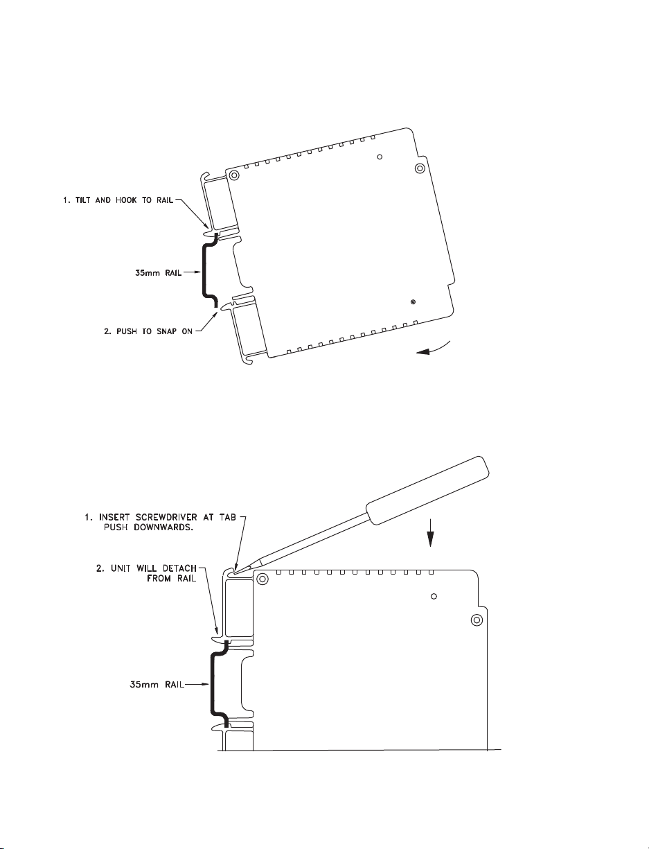
2.1.2 Mounting the DIN Rail iServer
To install unit onto DIN Rail:
a) Tilt unit, position mounting slot onto DIN Rail, as shown.
b) Push unit towards DIN Rail and it will snap into place.
Figure 2.2 Mounting - DIN Rail iServer
2.1.3 Removal from a DIN Rail
a) Insert flat screw-driver into tab and push downwards.
b) Unit will detach from DIN Rail.
Figure 2.3 Removal - DIN Rail iServer
4
Page 11
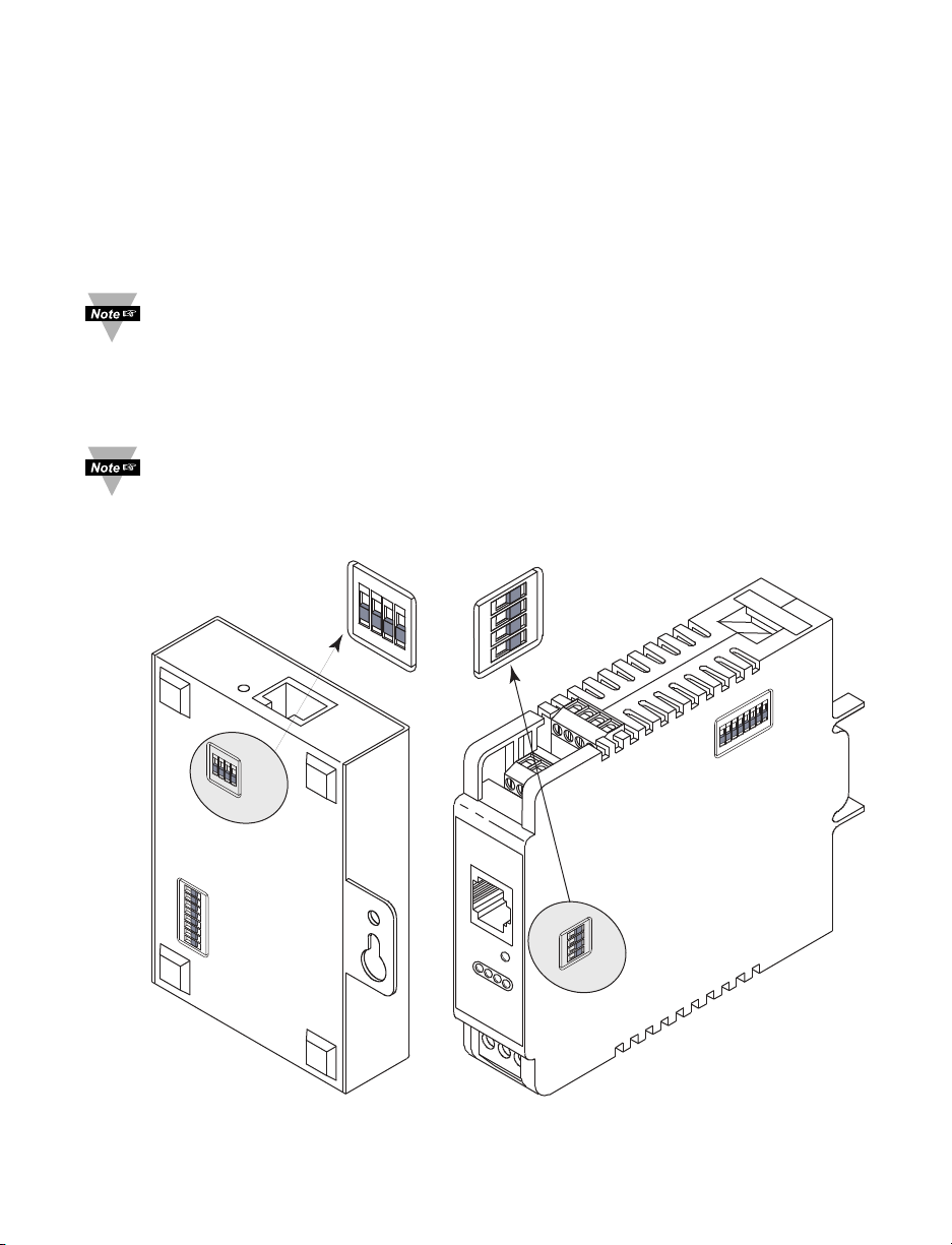
2.2 DIP Switches
2.2.1 SW1 DIP Switch Usage
The iServer is shipped with all SW1 DIP switches in "OFF" position.
1) N/C - not used
2) To change to default factory settings
3) To enable/disable DHCP
4) N/C - not used
To set the iServer to factory default settings, slide SW1 DIP switch #2 to ON
position. Power the iServer on and wait about 10 seconds until the iServer fully
boots up. Set the SW1 DIP switch #2 back to OFF position (it does not matter if
the iServer is powered ON or OFF, just make sure that the DIP switch is set to
OFF, otherwise, every time the unit is power-cycled the factory settings will take
over.
To enable the DHCP, besides using SW1 DIP switch #3, set the iServer’s IP
address to 0.0.0.0. An iServer with IP address of 0.0.0.0 will request an IP
address, gateway address, and subnet mask from the DHCP server over the
Ethernet.
ON
SW1
SW3
ON
SW1
OFF
1
2
3
4
ON
ON
1
2
OFF
3
4
8
7
6
5
4
OFF
3
2
1
4
3
2
1
OFF
SW1
ON
SW1
4
3
2
1
OFF
OFF
ON
8
Figure 2.4a DIP Switch SW1 Figure 2.4b DIP Switch SW1
Wall Mount iServer DIN Rail iServer
1
SW3
5
Page 12
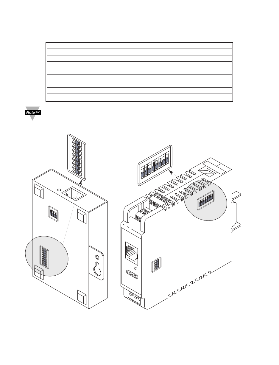
2.2.2 SW3 DIP Switch Usage
The iServer is shipped with all SW3 DIP switches in "OFF" position (signal 5V max).
SW # DESCRIPTION CHANNEL
1 PULL DOWN (1K ohm) CHANNEL A
2 PULL UP (3K ohm) CHANNEL A
3 PULL DOWN (1K ohm) CHANNEL B
4 PULL UP (3K ohm) CHANNEL B
5 HIGH INPUT SIGNAL (0-12 V) CHANNEL B
6 LOW MAGNETIC SIGNAL (120 mV) CHANNEL B
7 HIGH INPUT SIGNAL (0-12 V) CHANNEL A
8 LOW MAGNETIC SIGNAL (120 mV) CHANNEL A
Refer to Specifications Section 5 for SW3 jumper configurations.
ON
SW1
SW3
SW3
ON
1
2
3
4
8
7
6
5
4
OFF
3
2
1
ON
OFF
8
7
6
5
4
3
2
1
OFF
OFF
ON
1
2
3
4
5
6
7
8
SW1
ON
4
3
2
1
OFF
SW3
OFF
ON
1
8
SW3
Figure 2.5a DIP Switch SW3 Figure 2.5b DIP Switch SW3
Wall Mount iServer DIN Rail iServer
6
Page 13
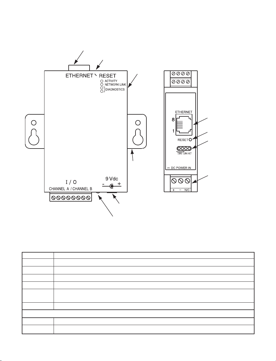
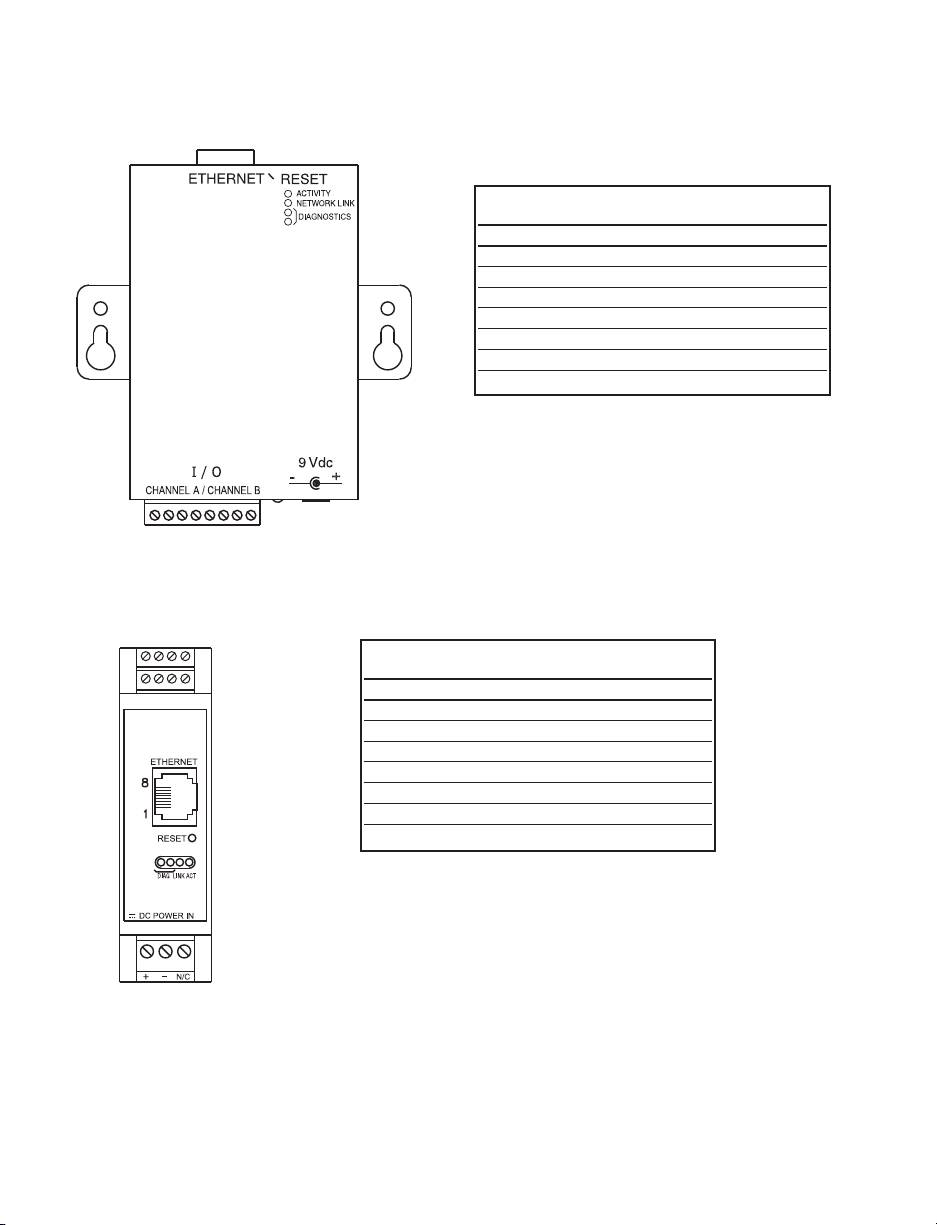
2.3 Parts of the iServer Unit
RJ45 interface
Reset Button
Mounting
Tabs
LEDs
1 2 3 4
5 6 7 8
I/O Connectors
Channel A
Channel B
RJ45 interface
Reset Button
LEDs
dc Power Input
1 2 3 4 5 6 7 8
dc Power Input
Power LED
Figure 2.6 Parts of the iServer Unit
Table 2.1 Parts of iServer Unit
ETHERNET RJ45 interface for 10BASE-T connection.
RESET Button: Used for power reseting the iServer.
I/O Connections for Channel A and Channel B, Refer to Section 2.4.
ACTIVITY LED (Red) Blinking: Indicates network activities (receiving or sending packets).
NET LINK LED (Green) Solid: Indicates good network link.
DIAG LED (Yellow and Green) Diagnostics: at boot-up they turn on for 2 seconds, then
turn off; DHCP: if DHCP is enabled, they blink and stay solid periodically
POWER LED (Green) Solid: Indicates Power-ON (for -W version only).
DC Power Supply Section:
+ Plus power supply wire connection (inside the plug for -W version).
- Minus power supply wire connection (outside the plug for -W version).
7
Page 14
2.4 Wiring
1 2 3 4
Figures 2.7 shows the signals on the 8 Position Connector.
I/O SIGNAL CHANNEL
CONN.
1 VCC CHANNEL A
2 GND CHANNEL A
3 OUT A CHANNEL A
4 IN A CHANNEL A
5 VCC CHANNEL B
6 GND CHANNEL B
7 OUT B CHANNEL B
8 IN B CHANNEL B
1 2 3 4 5 6 7 8
Figure 2.7a Wall Mount iServer 8 Position Connector
5 6 7 8
CHANNEL A
CHANNEL B
I/O SIGNAL CHANNEL
CONN.
5 VCC CHANNEL B
6 GND CHANNEL B
7 OUT B CHANNEL B
8 IN B CHANNEL B
1 VCC CHANNEL A
2 GND CHANNEL A
3 OUT A CHANNEL A
4 IN A CHANNEL A
Figure 2.7b DIN Rail iServer 8 Position Connector
8
Page 15
2.5 Network Communication Interfaces
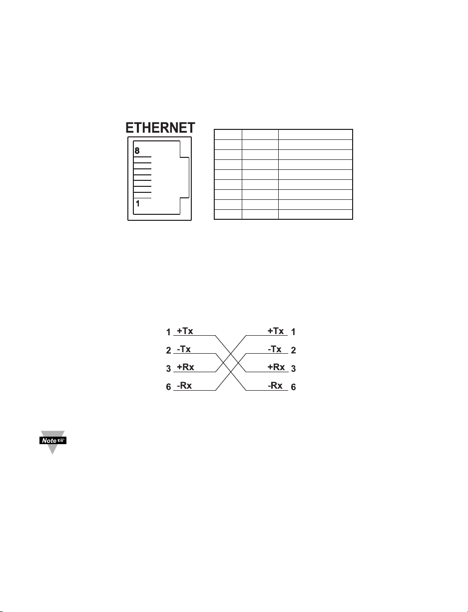
2.5.1 10Base-T RJ-45 Pinout
The 10BASE-T Ethernet network (RJ-45) system is used in the iServer for network
connectivity. The 10 Mbps twisted-pair Ethernet system operates over two pairs of wires.
One pair is used for receiving data signals and the other pair is used for transmitting data
signals. This means that four pins of the eight-pin connector are used.
Pin Name Description
1 +Tx + Transmit Data
2 -Tx - Transmit Data
3 +RX + Receive Data
4 N/C Not Connected
5 N/C Not Connected
6 -Rx - Receive Data
7 N/C Not Connected
8 N/C Not Connected
Figure 2.8 RJ45 Pinout
2.5.2 10Base-T Crossover Wiring
When connecting the iServer directly to the computer’s network port, the transmit data
pins of the computer should be wired to the receive data pins of the iServer, and vice
versa. The 10Base-T crossover cable with pin connection assignments are shown below
.
Figure 2.9 10Base-T Crossover Cable Wiring
Use straight through cable for connecting the iServer to an Ethernet hub. The
ports on the hub are already crossed.
9
Page 16

PART 3
NETWORK CONFIGURATION
3.1 Network Protocols
The iServer can be connected to the network using standard TCP/IP protocols.
It also supports ARP, HTTP (WEB server), DHCP, DNS and Telnet protocols.
3.2 Ethernet (MAC) Address
MAC (Media Access Control) address is your computer's unique hardware number.
When you're connected to the LAN from your computer, a correspondence table relates
your IP address to your computer's physical (MAC) address. The MAC address can be
found on a label attached to your device and contains 6 bytes (12 characters) of
hexadecimal numbers XX:XX:XX:XX:XX:XX hex
For example: 0A:0C:3D:0B:0A:0B
Remove the small label with the default IP address and there will be room to put
your IP address. See Figure 3.1
MAC ADDRESS
LABEL IN
HEX CODE
iSERVER'S VERSION #
REMOVE DEFAULT
IP ADDRESS LABEL
AND PUT NEW
CUSTOMER'S
IP ADDRESS
MODEL NO:
SERIAL NO:
INPUT POWER:
IP:
#.#
MODEL NO:
SERIAL NO:
INPUT POWER:
IP:
Figure 3.1 Labeling
101011
#.#
REMOVE DEFAULT IP
ADDRESS LABEL AND PUT
NEW CUSTOMER'S
IP ADDRESS
MAC ADDRESS
LABEL IN
HEX CODE
iSERVER'S VERSION #
Page 17

3.3 DHCP
DHCP, Dynamic Host Configuration Protocol enables individual computers or devices to
extract their IP configurations from a server (DHCP server). If the DHCP is enabled on
your iServer, as soon as the iServer is connected to the network, there is an exchange of
information between DHCP server and the iServer. During this process the IP address,
the Gateway address, and the Subnet Mask will be assigned to the iServer by the DHCP
server. Note that the DHCP server must be configured correctly to do such assignment.
If fixed or static IP address is desired, the DHCP must be disabled. The iServer is
shipped with DHCP disabled (factory default). The DHCP can be enabled by setting the
SW1 DIP switch # 3 to the “ON” position (refer to Figure 3.2).
ON
OFF
4
SW1 DIP switch # 3 shown in “ON” position
3
2
1
Figure 3.2 SW1 DIP Switch
3.4 DNS
DNS, Domain Name System enables individual computers and devices to be recognized
over a network based on a specific name instead of an IP address. For example, instead
of having to use http://192.168.1.200 (IP address), you would use only http://eis03ec or
any eight character name stored as Host Name under Access Control page in the iServer
Home Page. The default DNS name for an iServer is "eis" followed by the last four digits
of the MAC address of that particular iServer.
1. It is very important to communicate with the network administrator in order to
understand the DHCP and its existing configurations on the host server,
before enabling the DHCP on the iServer.
2. The iServers are shipped with a default static IP address of
192.168.1.200 and Subnet Mask of 255.255.255.0.
3. On Novell networks or Windows 2000 Server where the DCHP is an updated
function of DNS, this feature may be beneficial since a particular name can
be assigned eliminating the need for the IP address, as described in
Section 3.4.
Page 18

3.5 IP Address
Every active device connected to the TCP/IP network must have a unique IP address.
This IP address is used to build a connection to the iServer. Every computer using
TCP/IP should have a unique 32-bit address. It is divided into two portions, the network
ID and the host ID. For instance, every computer on the same network uses the same
network ID. At the same time, all of them have a different host ID. For more details about
the IP address see Appendix B.
3.5.1 Default IP Address
The iServer is shipped with a default IP address set to 192.168.1.200 and Subnet Mask
of 255.255.255.0. If you are going to use a Web browser or Telnet program to access
the iServer using its default IP address, make sure that the PC from which you’re
establishing the connection has an IP address that is in the same range as the iServer’s
IP address (192.168.1.x, where x can be any number from 1 to 254.
Your PC’s IP address cannot
be the same as the iServer’s IP address).
You also need to make sure that your PC’s Subnet Mask is 255.255.255.0. This is a
good way to access the iServer over the network and make any configuration changes
needed. If the factory default address is already in use on your network, use an Ethernet
crossover cable between your computer and the iServer and modify the IP address or
any other settings within the iServer.
3.6 Port Number
All TCP connections are defined by the IP address and a port number. A port number is
an internal address that provides an interface between an application running on your
computer and the network through the TCP/IP protocol.
There are three default TCP socket port numbers assigned to the iServer:
1. Port (socket) number 1000 when using HTTPGET program.
2. Port (socket) number 2000 when trying to access the device connected to
the port of the iServer to receive signals.
3. Port (socket) number 2002 when trying to access the iServer itself for Power
Recycling the iServer remotely. This can be done using Windows standard Telnet
application. Refer to Section 4.8 for more information.
12
Page 19

PART 4
OPERATIONS
This iServer can be used and configured in several ways, depending on user’s
preference and network setup. It can be configured using a Web browser, like Netscape
or Internet Explorer. It can also be configured using NEWPORT’s iCONNECT
Configuration Software. In addition to iServer operation, it can also be used in Telnet
simulation mode where it emulates serial communication operation over a network cable
If DHCP and DNS servers are used, the connection is very simple, no need to find the
right IP address or watch for network conflicts, these are done for you by your network
DHCP and DNS server. All that is left for you to do, is to use a straight network cable to
connect the iServer to a hub and power it up.
Instead of connecting the iServer directly to your network, you can configure your
PC’s network connection with an IP address (192.168.1.x) that is in the same
range as the iServer’s default IP address (192.168.1.200) and connect to the
iServer using a cross-over network cable between your PC’s network port and the
iServer.
Go to your computer that is connected to the same network and from the MS-DOS Prompt
window type "ping 192.168.1.200” and press Enter. If DHCP and DNS servers are used
type “ping eisxxx”, where xxxx are the last four digits of the iServer’s MAC address,
located on the device (see Figure 3.1). You should get a reply as shown in Figure 4.1.
4.0 Testing the Connection
C:\>ping eis03ec�
Pinging eis03ec with 32 bytes of data:�
�
Reply from eis03ec: bytes=32 time=15ms TTL=60�
Reply from eis03ec: bytes=32 time=8ms TTL=60�
Reply from eis03ec: bytes=32 time=8ms TTL=60�
Reply from eis03ec: bytes=32 time=8ms TTL=60�
�
Pinging statistics for eis03ec:�
� Packets: Sent=4, Received=4, Lost=0 (0% loss)�
�
Approximate round trip times in milli-seconds:�
� Minimum=8ms, Maximum=15ms, Average=9ms
Figure 4.1 Pinging the iServer from MS-DOS Prompt
This proves that the connection is proper and you can get into configuration or run mode
using the Telnet or Web browser.
13
Page 20
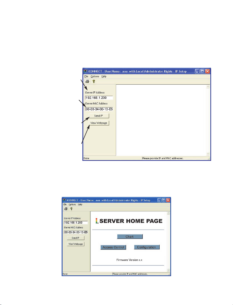
4.1 iCONNECT Software
The iServer may also be assigned an IP Address by using the iCONNECT software.
a) Download the iCONNECT software from the website listed in this manual.
b) Install iCONNECT software on a networked PC. This software is compatible with Windows
95, NT, 2000, and XP.
c) Use iCONNECT to assign an IP address to the iServer and access its web pages for
configuration. You can also use any standard web browser to access the iServer’s web
pages. Consult with your IT department for obtaining an IP address.
Place the IP address in this box
Take the MAC address from the
label attached to the bottom of
the iServer and place it in this
box
Click here to send the above IP
address to the iServer
After the IP address is assigned
to the iServer, click here to
access its web pages
Figure 4.2 Assigning an IP Address using iCONNECT
d) To access the iServer for Configuration:
Click on the “View Webpage” button, you will access the iServer’s Home page, refer to
Section 4.3 for details.
Figure 4.3 Accessing the iServer’s Home Page
14
Page 21

4.2 Setting a New IP Address over the Network
Besides using the iCONNECT software, you may use the iServer’s default IP address to
access it and assign a new IP address to it.
The iServer is shipped with a default IP address of 192.168.1.200 and Subnet Mask of
255.255.255.0. You can configure your PC’s Network connection with an IP address that
is in the same range as the iServer’s IP address (192.168.1.x) and connect to the iServer
using a crossover network cable between your PC and the iServer.
With this completed, you can go to the DOS-Prompt and ping 192.168.1.200. If you
receive responses back (Figure 4.1), you can go to a Web browser and type in
http://192.168.1.200 and it will take you to the iServer’s main web page.
Select Access Control button, you’ll be asked for the password. The default Login
password is "12345678" and the Admin password is "00000000", then you should be on
the Access Control page were you can simply type in the desired Static IP address, and
click Save.
ACCESS CONTROL
Address
http://192.168.1.200
ACCESS CONTROL
Login Password 12345678
Admin Password
Host Name eis21d9
MAC Address 00:03:03:00:21:D9
IP Address 192.168.1.200
Gateway Address
Subnet Mask
00000000
0.0.0.0
255.255.255.0
Save Reset
Power Recycle
Main Menu
Figure 4.4 Access Control
For the IP address to take effect, the iServer needs to be turned OFF/ON or pressing the
physical button marked “RESET” on the iServer
You can now connect the iServer to an Ethernet hub using a straight through cable,
power it up, and follow the ping routine mentioned in the previous section.
Refer to Section 4.12 for detailed descriptions and functions of the Access
Control Page.
15
Page 22
4.3 Setup and Operation Using a Web Browser
• Start your web browser.
• In the URL field, type http://eisxxxx
address label located on the device
• If a static IP address is used, then simply type http://x.x.x.x, where x.x.x.x is the
iServer’s IP address.
• The Home Page will be displayed.
SERVER HOME PAGE
Address
http://192.168.1.200
using the last four-digits from the MAC
(see Figure 3.1)
if DHCP and DNS are used.
SERVER HOME PAGE
Chart
Access Control
Configuration
Firmware Version x.x
Figure 4.5 iServer Home Page Menu
If a blank screen appears without any “java application running” or image of a
“Java logo”, please verify you have the latest Java Runtime Environment
installed and setup according to the following instructions in Section 4.5. If you
do not have Java Runtime Environment, you may download it from our website
or contact the Customer Service Department nearest you.
16
Page 23
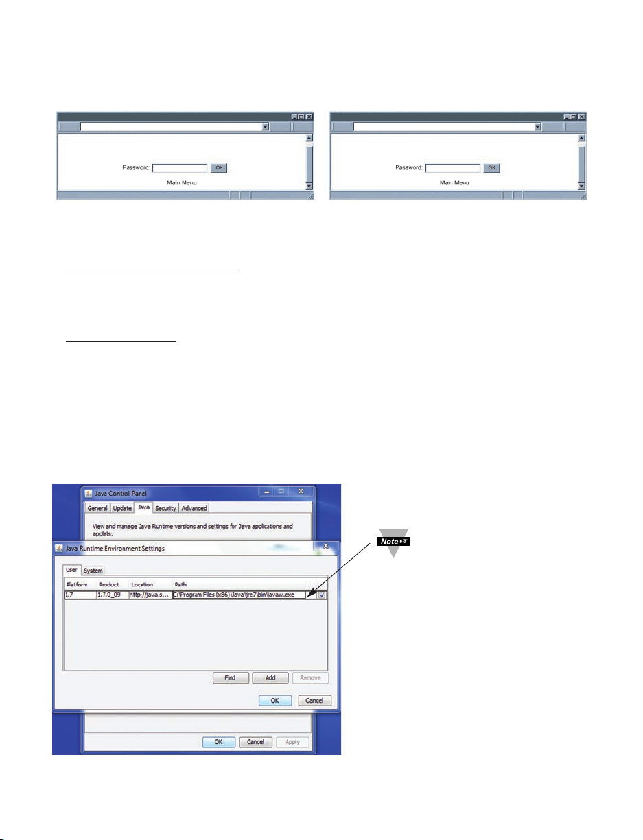
4.4 Login
In order to access certain menu items of the Home Page, users may be prompted for a
password, as shown in Figure 4.6.
LOGIN
http://192.168.1.200 http://192.168.1.200
LOGIN
ADMINISTRATOR
ADMINISTRATOR
Figure 4.6 LOGIN and ADMINISTRATOR Passwords
There are 2 different access levels:
1. ADMINISTRATOR Password (administrator) allows certain groups and individual users to
access and modify "entire" iServer parameters without any restrictions.
The default password is 00000000. This password can be up to 16 alphanumeric case-
sensitive characters.
2. LOGIN Password (operator) allows users to access and modify the iServer parameters
except the “Acess Control” which requires an Administrator password.
The default password is 12345678. This password can be up to 16 alphanumeric
case-sensitive characters.
4.5 Java Runtime Environment 1.7 Setup instructions
If your computer does not have Java installed, please download from java.sun.com. You
can change the Java setting by clicking its icon in Control Panel. To load the applet, you
have to enable the web browser and disable cache.
1. Go to your computer's Control Panel. Open the Java Plug-in
Figure 4.7 Java 1.7 Screen Shot
17
Verify that
the path is
correct.
Page 24

4.5.1 Browser Proxy Selection
Accessing iServer units within your internal network
• Usually when the computer and iServer are on an internal network, you will not use
Proxy server access.
• You should un-check the "Use Browser Settings" option on the "Proxy" tab.
Accessing iServer units using the internet
• Often the web browser will use Proxy server access to the internet. In such cases,
the default Java runtime settings on the "Proxy" tab should suffice. The default
setting is the "Use Browser Settings" option.
• If the default proxy setting doesn't work, then you may have a situation where the
proxy settings of the web browser are incorrect.
Diagnostics:
If the web page of the iServer appears, then the HTTP Proxy is working fine.
If the data isn't updated on the iServer upon selecting the Read Sensor web page, there
may be a problem with access through a winsock proxy server. In such cases your network
administrator will need to provide the winsock proxy server and port #s. (If the administrator
requires knowledge of the port # required on the iServer, the value is 2003).
These values should be entered into the Socks line on the "Proxy" tab (of the Java Plugin
control panel) or into the "connections" tab on the View,Internet Options dialog and make
sure that the Proxy tab shows that the "Use Browser Settings" option is not selected (i.e.
when you specify proxy connections in the Java Plugin control panel.
Accessing iServer units over Peer-to-Peer network
A simple peer-to-peer network is setup by disconnecting from the main network (as users
will often do when trying to do initial setup of the iServer) and then connecting the iServer
to another computer using a ethernet hub, an ethernet switch, or a Cross-over cable
connection.
Often when using a peer-to-peer network, the Java plugin and the web browser (such as
Internet Explorer) have internet connections configured to connect through proxy servers.
In such case, you will need to simply assign the final IP address on this peer to peer
network and then view the iServer charts after connecting the iServer into the regular
network. Otherwise you can disable the Java plug-in's "Use Browser Settings" temporarily
and then reconfigure the Java plug-in settings for regular network access after testing the
iServer chart access on your peer-to-peer network.
The "Use Browser Settings" should not be selected. And the HTTP and Socks proxy
entries should be blank. Also, setup the internet browser so that proxy servers are disabled.
Java and the Java Coffee Cup Logo are trademarks or registered trademarks of Sun Microsystems, Inc. in the U.S. and other countries."
If you still have problems viewing the page and you are on a Proxy Server or are
behind a Firewall, please contact your MIS administrator to verify that you have
the lastest Proxy Client Software, version 2.0 or higher.
18
Page 25

4.6 iServer Operation Basic Menus
4.6.1 Chart Descriptions
SERVER HOME PAGE
http://192.168.1.200
A
B
D
F
(BAR CHART)
G
J4J3J2J1
K
Rate Monitor
CH A: 3088 HZ CH B: 4561 HZ
A
SP1
B
SP2
AB
0.0
Message:
a=Frequency ;b=0.0;c=3089;d=4559 ;e=Rate Monitor; f=HZ; g=101; h=5000;i4000;j=1;k=1;l=+;m=12:50:03 Nov,22 2003;
a=Frequency ;b=0.0;c=3092;d=4563 ;e=Rate Monitor; f=HZ; g=001; h=5000;i4000;j=1;k=1;l=+;m=12:50:04 Nov,22 2003;
a=Frequency ;b=0.0;c=3088;d=4561 ;e=Rate Monitor; f=HZ; g=101; h=5000;i4000;j=1;k=1;l=+;m=12:50:05 Nov,22 2003;
R & D Engr.Lab
5000 4000SP1 SP2
3088.0
4561.0
4000.0
1Minute(1Sec/Div)
Mon Nov 24 15:57:43 PST 2003Mon Nov 24 15:24:05 PST 2003
5000.0
Bar
C
E
100000
H
Reset Latch A Reset Latch BReset Timer
Applet pulse started
L1 L2 L3
Figure 4.8 Chart Descriptions
A) Chart’s Title name decided by the user.
B) Experiment/Task’s Name decided by the user.
Refer to Section 4.7 Device/Configuration Page’s Descriptions and Setup for
editing the Chart’s Title and Experiment/Task’s Name.
C) Alarm Setpoint 1 or Alarm Setpoint 2 setup. Type in the desired values and hit enter
key, the square shape dot symbolizes the Alarm Status Indicator, which is normally
Black and will turn Red if the alarm is activated.
D) Digital Display of Dual Input channels, it can display in any engineering units
required. Blue for CH A in cyan color background and red for CH B in yellow color
background. In this example, it is the reading of frequencies of 2 Signal Generators.
To display your own-defined Unit, Refer to Section 4.7 Device/Configuration
Page’s Descriptions and Setup for editing and modification.
19
Page 26

4.6.1 Chart Descriptions (continued)
E) Chart Option Pull-Down Menu, which allows users to select Bar chart type Figure 4.8
or Line chart type Figure 4.9.
F) Graphical Display of Chart, either Bar or X-axis Line Chart.
G) Enter your setting for Minimum Range of Measurement for graphical display.
H) Enter your setting for Maximum Range of Measurement for graphical display.
Those two settings will reset to default (100 max. and 0 min.) if there is any
change made from Configuration or Chart refresh. To modify, just type in the
desired values and simply hit enter key.
J1) The square dot will flash between 2 colors red & green as representing a Network
Communication Activity Indicator as device successfully connecting otherwise
remaining red if there is problem with connection or Network disconnected.
J2) Start Date and Time of the Experiment / Measurement Task.
J3) X-Axis Time Scale Option Pull-Down Menu for Line Chart. There are 6 options
available to users as the following:
1 Minute (1 Second/Div)
1 Hour (1 Minute/Div)
1 Day (1 Hour/Div)
1 Week (1 Day/Div)
1 Month (1 Day/Div)
1 Year (1 Month/Div).
J4) Current Date and Time of the Experiment/Measurement Task. It is synchronized
with users’ operating system.
Any modification or change that is made and saved from Configuration Page will
restart the Chart.
20
Page 27

4.6.1 Chart Descriptions (continued)
K) Message Window is described below.
Table 4.1 Message Item Window Description
Message: Content Description:
Item: Function
a Device Measurement Mode/Type
b CH A & CH B Combined input reading (A-B F or A-B T mode)
c CH A input reading value
d CH B input reading value
e Your own-defined Name of Experiment/Measurement Task
f Unit of Input Value (definable)
g = 3 bits: 1st bit: the transmit active bit
2nd bit: the SP1 active bit
3rd bit: the SP2 active bit
h SP1 (setpoint 1) value (A Batch value if Batch mode used)
i SP2 (setpoint 2) value (B Batch value if Batch mode used)
j Batch A Number (Number of A Batches)
k Batch B Number (Number of B Batches)
l A-B mode sign. (+, -, x and /)
m User-definable time/date stamp of Input Reading.
This time/date stamp will reset to default if the device’s
power was recycled.
These Message Item Windows will restart with new data after 10 lines of data.
L1) Click this button to restart or to revert the measurement to specific number or a
device condition to a specific state such as Zero or SetPoint.
L2) Click this button to reset Alarm SetPoint Latched condition of Channel A.
L3) Click this button to reset Alarm SetPoint Latched condition of Channel B.
In order to be able to using those above Reset Functions’ buttons, users will be
prompted at Login page for password once.
21
Page 28

4.7 Device Configuration Page Items’ Description and Concepts of Setup:
From the Home Page click on CONFIGURATION button to get to the Configuration/Device
Setup page (see Figure 4.9). Users will be prompted with a Login Page to enter a
password, default password is 12345678 and then click OK.
There are five types of settings in the Configuration Page, which should be saved by the
reserved Save Button:
• Device Type / Operation Mode Selection.
• SetPoint / Alarm Operation.
• Title Definability Utility
• Operation Condition Parameters.
• Terminal / Remote (Tunneling) Setup.
CONFIGURATION
http://192.168.1.200
R & D Engr.Lab
Device Type Selection
SP1 Value
SP1 Latch Mode
SP1 Active Mode
SP1 Dead Band
SP1 Active Status
SP2 Value
SP2 Latch Mode
SP2 Active Mode
SP2 Dead Band
SP2 Active Status
TCP/UPD
Server Type
Number of Connections
Port
Remote Access
Remote Port
Remote IP Address
0.0.0.0
5.00000000e+03
Unlatch
Above
0
4.00000000E+03
Unlatch
Above
0
Save
TCP
Continuous
2000
disable
2000
Save Save
High
High
Frequency
Name
Rate Monitor
Unit of Measure
R&D Engr.Lab
Title
A Scale
1.00000000E-00
A Offset
A Gate Time (mS)
A Debounce Time (mS)
B Scale
B Offset
B Gate Time (mS)
5
B Debounce Time (mS)
Reading Format
Number of Digits
Decimal Point
A-B Mode
Counter Mode
0
1.00000000E-00
0
Save
HZ
Save
0
0
1000
0
Decimal
9
0
+
Count UP
Figure 4.9 Configuration/Device Setup
22
Page 29

4.7.1 Device Type/Mode Selection:
This is one of the first choice that users must decide and choose to operate device for
the requirement of applications. Using your Web Browser, users can configure this
device to operate either with universal single or dual input channels in following available
modes as Device Type Selection Pull-Down Menu illustrated:
Device Type Selection
Frequency
Save
Totalizer
Batch
A-B F Mode
A-B T Mode
Quadrature
4.7.1.1 Frequency Mode:
Totalizer Gate
This mode (factory default) configures the iServer to operate as a single or dual input
frequency counter, range 1 to 100 KHz, or dual rate meter that counts per unit time.
The iServer displays the units of measurement of 2 input signal sources as CH A and CH
B in Blue or Red respectively. The chart allows user-definable engineering units.
Both Line or Bar chart Option are available.
Users can monitor the values in 6 different time scales available from 1 min. to 1 year
history of experiment time duration.
Use scale to convert input frequency unit to units other than Hertz (Hz) as definable by
users and suitable for any application requirement.
For Frequency Mode ID, observe Message Item Window and notice items following:
a= Frequency
c=CH A input pulse/frequency reading value
d=CH B input pulse/frequency reading value
Make certain that Debounce Time must be zero to operate in this
Frequency mode.
Set jumper for selecting low-level input if the reading is not displayed.
Refer to Specifications Section 5 for SW3 jumper configurations.
23
Page 30

4.7.1.2 Totalizer Mode
This mode is operated commonly as event counter or recorder as either with single A or
B channel or If there are dual inputs, both Input values will be totalized or accumulated
and displayed graphically and digitally until Reset Timer Button restart measurement of
both Channels at zero or the Offset values.
However Users must readjust Max. or Min. Range Values between measurement values
to keep Line Chart fully displaying as once reset executed. Device now is UP & DOWN
32-bit Counter ranging between (–2147483647 and +2147483647). Users must access
Configuration Page to setup device for this mode.
For Totalizer Mode ID, observe Message Item Window and notice items following:
a= Totalizer
c=CH A input count reading value is totalizing: CH A Total count
d=CH B input count reading value is totalizing: CH B Total count
For Example: To compare and monitor PCB (Printed Circuit Board) Assembling
Productivities of 2 machines or 2 types of product with specified time period by selecting
suitable x- Axis Time Scale Option according to your company’s demand, Figure 4.10 is
one of example, this device offers the most typical and user-friendly illustration and
clarity as setup with this Totalizer Mode.
Make certain that Debounce Time must be zero when operating with
frequency signals.
24
Page 31

4.7.1.2 Totalizer Mode (continued)
SERVER HOME PAGE
http://192.168.1.200
Assembly Dept.
PCB Productivity
120 6000SP1 SP2
CH A: 4526 PCBs CH B: 5363 PCBs
Message:
a=Totalizer;b=0.0;c=4423;d=5240;e=PCB Productivity;f=PCBs;g=010;h=120;i=6000;j=463;k=3524;l=+;m=12:50:03 Nov,22 2003;
a=Totalizer;b=0.0;c=4474;d=5302;e=PCB Productivity;f=PCBs;g=110;h=120;i=6000;j=463;k=3524;l=+;m=12:50:04 Nov,22 2003;
a=Totalizer;b=0.0;c=4526;d=5363;e=PCB Productivity;f=PCBs;g=010;h=120;i=6000;j=463;k=3524;l=+;m=12:50:05 Nov,22 2003;
Applet pulse started
1Minute(1Sec/Div)
Reset Latch A Reset Latch BReset Timer
Mon Nov 24 15:57:43 PST 2003Mon Nov 24 15:24:05 PST 2003
Chart
100000
Figure 4.10 Example of Totalizer Mode
25
Page 32

4.7.1.3 Batch Mode
This mode is for either single or dual input counting and monitoring visually number of
definable batches that is required by users’ application. To setup Batch value (unit count)
and Batch mode, users must access Configuration Page for detail of setting descriptive
parameters. However users should notice the following important items on Chart:
SP1 must be also understood as actual A Batch (unit count) value.
SP2 must be also understood as actual B Batch (unit count) value.
Batch A must be understood as Number of Batches counted via CH A.
Batch B must be understood as Number of Batches counted via CH B.
For Example: Machine A requires oil drop lubrication every 3199 PCB’s produced then
there must be done 89 times for 1 hour and Machine B requires a soft-reset every 12000
PCB’s produced then there must be done 28 times for 1 hour as Figure 4.11 illustrates. If
Time Scale Option of 1 Minute (1 Sec/Div.) is selected, Users can monitor process,
tracking time and be prepared for the required tasks in precise timely manner.
With the Example:
h=Machine A maintenance requirement: A Batch (unit count) value= 3199 PCB’s
i=Machine B system requirement: B Batch (unit count) value= 12000 PCB’s
j= Number of Batches (or lubrication) counted via CH A input= 89 times
k= Number of Batches (or soft-reset) counted via CH B input= 28 times
Make certain that Debounce Time must be zero when operating with
frequency signals.
26
Page 33

4.7.1.3 Batch Mode (continued)
SERVER HOME PAGE
http://192.168.1.200
Assembly Dept.
PCB Productivity
3199 89 2812000SP1 Batch A: Batch B:SP2
CH A: 727 PCBs CH B: 1986 PCBs
Chart
Message:
a=Batch ;b=0;c=620;d=1860;e=PCB Productivity;f=PCBs;g=000;h=3199;i=12000;j=89;k=28;l=+;m=12:50:03 Nov,22 2003;
a=Batch ;b=0;c=674;d=1923;e=PCB Productivity;f=PCBs;g=100;h=3199;i=12000;j=89;k=28;l=+;m=12:50:04 Nov,22 2003;
a=Batch ;b=0;c=727;d=1986;e=PCB Productivity;f=PCBs;g=000;h=3199;i=12000;j=89;k=28;l=+;m=12:50:05 Nov,22 2003;
Applet pulse started
1Hour(1Minute/Div)
Reset Latch A Reset Latch BReset Timer
Mon Nov 24 15:57:43 PST 2003Mon Nov 24 15:24:05 PST 2003
150000
Figure 4.11 Example of Batch Mode
For Batch Mode ID, observe Message Item Window and notice items following:
a= Batch
c=CH A input count reading is totalizing and restart as Batch A value
reached/passed
d=CH B input count reading is totalizing and restart as Batch B value
reached/passed
h=CH A Batch (unit count) value
i=CH B Batch (unit count) value
j= Number of Batches counted via CH A input
k= Number of Batches counted via CH B input
27
Page 34

4.7.1.4 A-B F Mode
This mode is designed to operate with dual input pulse rate or frequency sources. Its
main function is to perform 4 common types of calculation (addition, subtraction,
multiplication and division) of 2 input values at a specific time and display the result
digitally as well as graphically with 2 types of chart, 6 types of time scale.
Users must access Configuration Page for setting this device operate under this mode,
first select option A-B F Mode from Device Type Selection (Operation Mode) Pull-Down
Menu then choose your type of Calculation:
+ : addition will calculate the sum of A+B
- : subtraction will calculate the difference of A-B
x : multiplication will calculate the product of A.B
/ : division will calculate the ratio of A/B.
From A-B Mode (Calculation Type) Pull-down submenu.
Chart of this A-B F Mode will have additional combined (calculation results of A&B) A-B
channels Value displayed digitally and graphically as a chart as illustrated in Figure 4.12.
This example displays the results of Dual Counts A and B with PCB’s is unit of counting.
• A-B: 200.6 PCB’s is the subtraction of (CH A: 257 PCB’s – CH B: 56.4 PCB’s)
in Green Color and Purple Color background.
• Third green line of Graph (between the top/blue of CH A and the bottom/red of
CH B) is representing the subtracted values of A-B on 1Hr/Div. Time Scale.
• Values of CH A and CH B are constant therefore the chart only shows all 3
straight lines.
Make certain that Debounce Time must be zero when operating with
frequency signals.
28
Page 35

4.7.1.4 A-B F Mode (continued)
SERVER HOME PAGE
http://192.168.1.200
Assembly Dept.
PCB Productivity
A-B: 200.6 PCBs CH B: 56.4 PCBs
Message:
a=A-B F Mode;b=200;c=257;d=56;e=PCB Productivity;f=PCBs;g=100;h=3199.9;i=12000;j=209;k=65;l=-;m=12:50:03 Nov,22 2003;
a=A-B F Mode;b=200;c=257;d=56;e=PCB Productivity;f=PCBs;g=100;h=3199.9;i=12000;j=209;k=65;l=-;m=12:50:04 Nov,22 2003;
Applet pulse started
3199.9 12000.0SP1 SP2
CH A: 257.0 PCBs
1Day(1Hour/Div)
Reset Latch A Reset Latch BReset Timer
Mon Nov 24 15:57:43 PST 2003Mon Nov 24 15:24:05 PST 2003
Chart
5000
Figure 4.12 Example of A-B F Mode
For A-B F Mode ID, observe Message Item Window and notice items following:
a= A-B F Mode
b= combined (calculated results of A&B) input reading value.
c=CH A input value
d=CH B input value
j= not applied ( previous Number of Batch Mode Measurement)
k= not applied ( previous Number of Batch Mode Measurement)
29
Page 36

4.7.1.5 A-B T Mode
This mode has almost the same setup procedure and operation as A-B F mode required.
However Dual input channels will be totalized and additional A-B T combined input
calculated values would change significantly except if A-B Mode pull-down Menu is
selected with “ / “ option (division calculation) as observed from the example in Figure
4.13 as A/B value always remained value of 3 PCB’s while the others are changing
rapidly.
Users must access Configuration Page for setting this device operate under this mode,
first select option A-B T Mode from Device Type Selection (Operation Mode) Pull-Down
Menu then choose your type of Calculation:
+ : addition will calculate the sum of A+B
- : subtraction will calculate the difference of A-B
x : multiplication will calculate the product of A.B
/ : division will calculate the ratio of A/B.
From A-B Mode (Calculation Type) Pull-down submenu.
For A-B T Mode ID, observe Message Item Window and notice items following:
a= A-B T Mode
b= combined (calculated results of A&B) input reading value.
c=CH A input count value is totalizing until users manually reset
d=CH B input count value is totalizing until users manually reset
j= not applied ( previous Number of Batch Mode Measurement)
k= not applied ( previous Number of Batch Mode Measurement)
Make certain that Debounce Time must be zero when operating with
frequency signals.
30
Page 37

4.7.1.5 A-B T Mode (continued)
SERVER HOME PAGE
http://192.168.1.200
Assembly Dept.
PCB Productivity
A/B: 3 PCBs CH B: 23733 PCBs
3199 12000.0SP1 SP2
CH A: 82916 PCBs
A
SP1
B
SP2
AB
Message:
a=A-B T Mode;b=3;c=81441;d=23310;e=PCB Productivity;f=PCBs;g=100;h=3199;i=12000;j=209;k=65;l=/;m=12:50:03 Nov,22 2003;
a=A-B T Mode;b=3;c=82163;d=23517;e=PCB Productivity;f=PCBs;g=100;h=3199;i=12000;j=209;k=65;l=/;m=12:50:04 Nov,22 2003
a=A-B T Mode;b=3;c=82916;d=23733;e=PCB Productivity;f=PCBs;g=100;h=3199;i=12000;j=209;k=65;l=/;m=12:50:05 Nov,22 2003
Applet pulse started
3.0
3199.0
12000.0
23733.0
1Day(1Hour/Div)
Reset Latch A Reset Latch BReset Timer
Mon Nov 24 15:57:43 PST 2003Mon Nov 24 15:24:05 PST 2003
Bar
82916.0
1000000
Figure 4.13 Example of A-B T Mode with Bar Chart
Users may constantly modify the Max or Min Range of Input Scale to accommodate with
the growing rapidly of totalized input values for proper and fully displayed chart.
31
Page 38

4.7.1.6 Quadrature Mode
This mode configures device to operate with two 90° phase shifted input signals A and B
from linear or rotational revolvers. The counting direction of Channel A is automatically
derived from the phase of the signals A and B that is designed for very fast, high-pulse
rate totalizing measuring and positioning applications and to utilize the outputs of Rotary
Pulse Generators (RPG’s), Tachometers, Motion Monitors and Controls Devices or
Equipments.
If Channel B input is disconnected its displayed Value will be the value of input signal of
Channel A and device is counting and displaying Channel A input signal as totalized
values on Channel A section of Chart.
For proper connection and configuration:
• Connect the main counting OUTPUT of RPG’s to channel A and the
Quadrature OUTPUT of most RPG’s to Channel B.
• Access Configuration Page and Select Quadrature option from Device Type
Selection (Operation Mode) Pull-Down Menu.
For Quadrature Mode ID, observe Message Item Window and notice items following:
a= Quadrature Mode
c=CH A input count value is totalizing until users manually reset
d=CH B input count value is Quadrature Signal or is actually Channel A input
frequency or rate with phase shifted normally 90° if Channel B input
disconnected
j= not applied ( previous Number of Batch Mode Measurement)
k= not applied ( previous Number of Batch Mode Measurement)
Make certain that Debounce Time must be zero when operating with
frequency signals.
32
Page 39

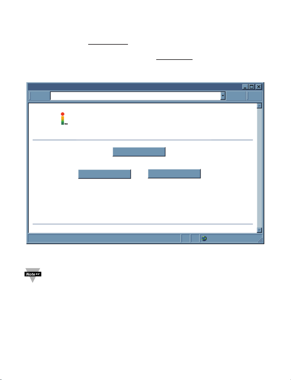
4.7.1.6 Quadrature Mode (continued)
SERVER HOME PAGE
http://192.168.1.200
Assembly Dept.
Motion Monitor
200 100SP1 SP2
CH A: 97574 PPR CH B: 1138 PPR
Message:
a=Quadrature ;b=0;c=95228;d=1138;e=Motion Monitor;f=PPR;g=011;h=200;i=100;j=2;k=0;l=/;m=12:50:03 Nov,22 2003;
a=Quadrature ;b=0;c=96411;d=1138;e=Motion Monitor;f=PPR;g=011;h=200;i=100;j=2;k=0;l=/;m=12:50:03 Nov,22 2003;
a=Quadrature ;b=0;c=97574;d=1138;e=Motion Monitor;f=PPR;g=011;h=200;i=100;j=2;k=0;l=/;m=12:50:03 Nov,22 2003;
Applet pulse started
1Minute(1Sec/Div)
Reset Latch A Reset Latch BReset Timer
Mon Nov 24 15:57:43 PST 2003Mon Nov 24 15:24:05 PST 2003
Chart
100000-10000
Figure 4.14 Example of Quadrature Mode
33
Page 40

4.7.1.7 Totalizer Gate Mode
This mode offers total control to users with the uses of Channel A to Controlling and
triggering signal to start, pause or restart the counting of totalizing Channel B input value
which is served as the main input for measurement. Users can manually control by just
creating an on-off toggle switch at the input terminal of channel A.
• Channel B starts counting / totalizing or pausing as soon as Channel A input
signal is rising that works similarly to a function of a toggle switch.
• Device initially requires a toggle signal from Channel A input to start
counting/totalizing from Zero or Offset value of Channel B.
• Reset Timer Button will stop the counting of Channel B measurement and
reset it to Zero or Offset value.
• Chart displays only Channel B.
For proper connection and configuration:
• Connect the main counting INPUT source for measurement to channel B input
terminal and the Totalizer Gate Input signal source for Controlling / Triggering
Channel B counting / totalizing operation.
• Access Configuration Page and Select Quadrature option from Device Type
Selection (Operation Mode) Pull-Down Menu.
For Quadrature Mode ID, observe Message Item Window and notice items following:
a= Totalizer Gate Mode
c=CH A input count value is totalizing until users manually reset
d=CH B input count value is Quadrature Signal or is actually Channel A input
frequency or rate with phase shifted normally 90° if Channel B input
disconnected.
Make certain that Debounce Time must be zero when operating with
frequency signals.
34
Page 41

4.7.1.7 Totalizer Gate Mode (continued)
SERVER HOME PAGE
http://192.168.1.200
Assembly Dept.
Motion Monitor
200 100SP1 SP2
CH B: 84206 PPR
Message:
a=Totalizer Gate ;b=0;c=0;d=81882;e=Motion Monitor;f=PPR;g=101;h=200;i=100;j=2;k=0;l=/;m=12:50:03 Nov,22 2003;
a=Totalizer Gate ;b=0;c=0;d=83100;e=Motion Monitor;f=PPR;g=101;h=200;i=100;j=2;k=0;l=/;m=12:50:04 Nov,22 2003;
a=Totalizer Gate ;b=0;c=0;d=84206;e=Motion Monitor;f=PPR;g=101;h=200;i=100;j=2;k=0;l=/;m=12:50:05 Nov,22 2003;
Applet pulse started
1Minute(1Sec/Div)
Reset Latch A Reset Latch BReset Timer
Mon Nov 24 15:57:43 PST 2003Mon Nov 24 15:24:05 PST 2003
Chart
1000000
Figure 4.15 Example of Totalizer Gate Mode
35
Page 42

4.7.2 SetPoint, Alarm and Alarm Output Operation Configuration
To setup Alarm1 / Alarm2 operations or Batches’ values
Locate the section as illustrated in Figure 4.16:
and access Configuration Page.
SP1 Value
SP1 Latch Mode
SP1 Active Mode
SP1 Dead Band
SP1 Active Status
SP2 Value
SP2 Latch Mode
SP2 Active Mode
SP2 Dead Band
SP2 Active Status
5.00000000e+03
Unlatch
Above
0
High
4.00000000E+03
Unlatch
Above
0
High
Save
Figure 4.16 Example of SetPoint / Alarm Configuration Section
Any edited/modified value with decimal point must be matched with existing
Decimal Point setting in Operation Condition Parameters Section 4.7.4.1.11 of
Configuration Page.
4.7.2.1 SP1 Value
Enter desired value for Alarm1 Setpoint or A Batch and its factory default value is 0.
Whatever number is entered for modifying The SP1 Value or A Batch will be displayed in
exponential format after SAVE button is pressed or clicked.
4.7.2.2 SP1 Latch Mode
Select either “Unlatch” (as default option) for unlatched Alarm1 operation or “Latch” for
latched Alarm1 operation.
4.7.2.3 SP1 Active Mode
Set device alarm activation Above (as default option) or Below SetPoint 1 value.
4.7.2.4 SP1 Dead Band
Enter desired value of Alarm1 Dead Band.
4.7.2.5 SP1 Active Status
Select the logic normal-state of Alarm1 Output and its factory default value is High.
36
Page 43

4.7.2.6 SP2 Value
Enter desired value for Alarm2 Setpoint or B Batch and its factory default value is 0.
Whatever number is entered for modifying The SP2 Value or B Batch will be displayed in
exponential format after SAVE button is pressed or clicked.
4.7.2.7 SP2 Latch Mode
Select either “Unlatch” (as default option) for unlatched Alarm2 operation or “Latch” for
latched Alarm2 operation.
4.7.2.8 SP2 Active Mode
Set device alarm activation Above (as default option) or Below SetPoint 2 value.
4.7.2.9 SP2 Dead Band
Enter desired value of Alarm2 Dead Band.
4.7.2.10 SP2 Active Status
Select the logic normal-state of Alarm2 Output and its factory default value is High.
For Alarm Status Monitoring or indicators, refer to Chart’s Items Description.
Any above settings must be saved for taking effect by its designated SAVE
button, which is localized in this section, before returning to Chart.
4.7.3 Title Definability Utility
This section of Configuration Page allows users define or name the desired Name of
Task/Experiment, Unit of Measure of application and Title of Chart and the space limits
as following:
Name: has max.16 characters
Unit of Measure: has max.16 characters
Title: has max.16 characters
Name
Unit of Measure
Title
Rate Monitor
HZ
R&D Engr.Lab
Save
Figure 4.17 Example of Title Definability Utility Section
Any above settings must be saved for taking effect by its designated SAVE
button which is localized in this section before returning to Chart.
37
Page 44

4.7.4 Operation Condition Parameters
This section of Configuration Page allows users to setup:
Input Reading Scale & Offset
Reading configuration: Gate time, Debounce time, Reading Format, Number of Digit
and Decimal Point.
Counting Mode: Direction and A-B Channel combined modes.
A Scale
A Offset
A Gate Time (mS)
1.00000000E-00
0
0
A Debounce Time (mS)
B Scale
B Offset
B Gate Time (mS)
1.00000000E-00
0
1000
B Debounce Time (mS)
Reading Format
Number of Digits
Decimal Point
A-B Mode
+
Counter Mode
Decimal
9
0
Count UP
0
0
Save
Figure 4.18 Example of Operation Condition Parameters Section
Failure of proper configuration will result in misled measurement data or no data
displayed.
38
Page 45

4.7.4.1 Input Reading Scale & Offset
Users can setup dual channel reading Scale and Offset as described following:
Any edited/modified value with decimal point must be matched with existing
Decimal Point setting in Operation Condition Parameters Section 4.7.4.1.11 of
Configuration Page.
4.7.4.1.1 A Scale:
Choose and setup up Channel A input reading displayed in different scale. Whatever
number is entered for modifying The A Scale value will be displayed in exponential
format after SAVE button is pressed or clicked.
4.7.4.1.2 A Offset:
Choose and setup up Channel A input counting value start in different point than zero.
4.7.4.1.3 B Scale:
Choose and setup up Channel B input reading displayed in different scale. Whatever
number is entered for modifying The B Scale value will be displayed in exponential
format after SAVE button is press or clicked.
4.7.4.1.4 B Offset:
Choose and setup up Channel B input counting value start in different point than zero.
Reading Configuration: Users may have no measurement reading on either CH A or CH
B digital display section, or no saved SetPoint setting displayed if these following
Reading Configuration Items as Gate Time, Debounce Time, Number of Digit and
Decimal Point are not selected correctly and properly:
4.7.4.1.5 A Gate Time (ms):
Length of time in which the Channel A of device accepts input pulses for a single rate
calculation. The longer Gate time, the better the resolution. (it is not used for the rate
calculation; a similar, but much more accurate method called Measurement Time is
used). Its default value is 1000 ms and its max. value is 65535.
4.7.4.1.6 B Gate Time (ms):
Length of time in which the Channel B of device accepts input pulses for a single rate
calculation. The longer Gate time, the better the resolution. Its default value is 1000 ms
and its max. value is 65535.
4.7.4.1.7 A Debounce Time (ms):
Length of time in which functions as the filter in case of the Channel A input is connected
with a contact closures signal to eliminate the de-bounce effect for better response of
readings.
4.7.4.1.8 B Debounce Time (ms):
Length of time in which functions as the filter in case of the Channel B input is connected
with a contact closures signal to eliminate the de-bounce effect for better response of
readings. Therefore Debounce Time must be zero (0) also as default if Frequency
Measurement or Mode is selected.
Make certain that Debounce Time must be zero when operating with
frequency signals.
39
Page 46

4.7.4.1.9 Reading Format:
Select 2 available Format options for all Readings as following: Decimal (as default) or
Exponent to display on the Chart.
4.7.4.1.10 Number of Digit:
For users’ application and equipment requirement of a limited number of digits to be
displayed properl.
For example: user may want to connect with remote display, which always has
hardware limitation in term of number of display digits. This feature must be use in
combination of Decimal Point setting because it only specifies limit the number of digits
before decimal point therefore if the measurement readings are exceeding the specified
setup Number of Digit, Channel A or B reading value will display “Overload”.
With the pull-down submenu, there are 10 available options from 0 to 9 to select for
users’ measurement value displayed.
4.7.4.1.11 Decimal Point:
With the pull-down submenu, there are 10 available options from 0 to 9 to select number
of decimal point.
4.7.4.2 Counting Mode:
There are two counting modes available as following:
4.7.4.2.1 Combined A-B mode:
Select from this pull-down submenu the calculation types to perform between values of 2
input signals and display the results with extra graph and digital values.
These modes require both input signals for measurement and are available as following:
+ (addition as default)
- (subtraction)
x (multiplication)
/ (division)
4.7.4.2.2 Counter Mode:
Select counting direction either UP (as default) or Down.
40
Page 47

4.7.5 Terminal / Remote (Tunneling) Server Setup
TCP/UPD
Server Type
Number of Connections
Port
2000
Remote Access
Remote Port
TCP
Continuous
5
disable
2000
Remote IP Address
0.0.0.0
Save
Figure 4.19 Terminal / Remote (Tunneling) Server Setup
4.7.5.1 TCP/UDP*:
The iServer supports TCP and UDP protocols (default is TCP). If UDP is selected, it can
be configured either for Broadcast UDP or Directed UDP. In case of Broadcast UDP, the
iServer will transmit the data to every node on the network. This can be accomplished if
the Remote IP Address is set to 255.255.255.255.
The Broadcast UDP is a practical solution when one iServer needs to communicate with
multiple nodes over the network. In the case of directed UDP, the iServer will transmit
the data to a specific node on the network. This can be accomplished if the Remote IP
Address is set to the IP address of that specific node.
4.7.5.2 Server Type:
Continuous mode sends all current measurement input values and update the graphic
chart to Ethernet, continuously, every one second. It is mainly used to send readings to a
remote display.
Command mode needs a command to query the iServer to get the response back to the
querying device. However all details of measurement are still updating including the
chart.
4.7.5.3 Number of Connections:
The range is from 0 to 5.
If 0 is selected, the Terminal Server feature is disabled.
1-5 (TCP mode) can allow the number of querying device to receive the response from
the iServer
If 1 is selected, only one network connection can be made to the device ’s Ethernet port.
Any number more than 1 would allow the network hosts to monitor (read only) the traffic
on the device ’s Ethernet port simultaneously, but only one network host would be
allowed to read and write (default is 5).
41
Page 48

4.7.5.4 Port:
Port 2000 is the default TCP port for the iServer’s port to which the device is connected.
Ports 1000 (used for HTTPget, refer to Section 4.9) , 2002, 2003, and 2004 are
reserved for internal use.
Terminal Server usually describes a device that exchanges data between
Ethernet/TCPIP networks and RS-232/RS-485 systems. With this iServer,
the data is obtained digitally from the device (irrelevant to RS-232 or RS-485
interface) and can be accessed from anywhere on the network.
A computer program, such as NEWPORT’s Mail Notifier, OPC Server, iLOG
or httpget can send TCP requests and obtain readings using the Terminal
Server feature.
4.7.5.5 Remote Access:**
Remote Access can be enabled and disabled.
*TCP/UDP: when UDP mode is selected, Remote Access should be disabled
and Remote IP and Port are the UDP remote listening IP and Port. If the
Remote IP is set to 255.255.255.255, the UDP packet becomes a
broadcasting packet which will allow any device listening to the Remote port
to receive the packet.
**If Remote Access is enabled, Terminal Server is automatically disabled.
4.7.5.6 Remote Port: (default 2000) the remote port number for the connection. Ports
1000 (used for HTTPget, refer to Section 4.9), 2002, 2003, and 2004 are reserved for
internal use.
4.7.5.7 Remote IP Address: iServer can establish a connection to a remote device (e.g.
an iLD Remote Display with iServer) with this IP.
42
Page 49

4.7.5.8 List of Available Communication Commands:
Table 4.2 List of Communication Commands
Command Command Function
List Response
a=xxx Device Measurement Mode/Type
b=xxx CH A & CH B Combined input reading (A-B F or A-B T Mode)
c=xxx CH A input reading value
d=xxx CH B input reading value
e=xxx Your own-defined Name of Experiment/Measurement Task
f=xxx Unit of Input Value (definable)
*SRP g=ABC = 3 bits:
A=1st bit: the transmit active bit
B=2nd bit: the SP1 active bit
C=3rd bit: the SP2 active bit
h=xxx SP1 (setpoint 1) value (A Batch value if Batch mode used)
i=xxx SP2 (setpoint 2) value (B Batch value if Batch mode used)
j=xxx Batch A Number (Number of A Batches)
k=xxx Batch B Number (Number of B Batches)
l=xxx A-B mode sign.
M=xxx User-definable time/date stamp of Input Reading.
*SRR A-B mode reading
*SRA Channel A input reading
*SRB Channel B input reading
*SRX Reset_A Reset Channel A counter to 0
*SRY Reset_B Reset Channel B counter to 0
43
Page 50

4.8 Telnet Setup
Telnet stands for Telecommunications Network, is a protocol that provides a way for
users (or clients) to connect to computers (or servers) on a network, whether in the next
building or across the world.
Example: C:\>Telnet 192.168.1.200 2002
You will then get the following screen.
C:\
Telnet 192.168.1.200
Type "reset"
to reboot
the server
The default
Firmware Version x.xx
Admin. Password:00000000
Admin. Login Successful
reset
The unit will reset in 5 seconds
_
Admin. Password
Figure 4.20 Telnet Login into the iServer
You can open a Telnet session using other terminal emulation programs like Tera Term
Pro (downloadable from the internet), which is a free software for MS-Windows. It
supports VT100 emulation, Telnet connection and serial com port connections.
Set the Number of Connections to 1-5 (not 0) using telnet simulation program connect to
the iServer.
In Continuous mode, the telnet teminal will receive continuous messages from the
iServer.
In Command mode, the command can be sent to query the iServer and get a response
back. Refer to Figure 4.20
4.8.1 Send Remote Reset:
Telnet port 2002 will bring a terminal for admin password. After typing the password and
following with the end character, the message Admin. Login Successful will be showed
on the terminal. Now type "reset" following with return character to reset the iServer. If no
character is received within 20 second, the terminal will be closed automatically.
4.8.2 Send Commands Manually:
Setup check list as following:
Telnet port 2000
Number of Connections is different than 0
Command mode
Telnet session is opened by Tera Term Pro software
Commands as listed from Table 4.2
44
Page 51

4.8.3 Sending *SRP command for Data Parameter String
Refer to Figure 4.21, the response is identical to the Message Item Window display
data. Refer to Table 3.1 iServer Device Chart for details.
C:\
Telnet 192.168.1.200
a=Frequency ;b=0.0;c=705.8;d=216.0;e=Dual F.Counter; f=Hz; g=111; h=0.0;i=0.0;j=0;k=0;l=+;m=04:25:46 Jan,02 2003;
Figure 4.21. Response of Command *SRP inquiry Using Terminal Setup
4.8.4 Remote Display Format for Measurement Readings:
Terminal Server setup check list as following:
Telnet port 2000
Number of Connections is different than 0
Continuous mode
Telnet session is opened by Tera Term Pro software
4.8.5 A-B Mode:
This is an example of A+B frequencies Mode or A-B F mode and A-B mode is +. A is the
value of Frequency input at Channel A input, B is the value of Frequency input at
Channel B input and R is the result or sum of A+B values. Refer to Figure 4.22.
Tera Term - 192.168.1.200 VT
File Edit Setup Control Window Help
B 216.4
R 922.2
A 704.3
B 215.5
R 922.1
A 704.0
B 216.1
R 920.5
A 706.1
B 216.0
R 921.4
A 706.1
B 215.3
R 921.1
A 705.1
B 215.9
Figure 4.22 Dual Frequency Counter in A-B (+) Mode is Displayed Under
Continuous Mode Using Remote Terminal Server
45
Page 52

4.9 HTTPGET Program
The Httpget software is used to send a single HTTP or TCP request to an iServer
product. In contrast, the telnet or Hyperterminal programs allow a continuous
connection with multiple requests to be sent to the iServer product.
Generally httpget is used for simply programming an IP address to the iServer or for
quickly obtaining a reading of from a device.
The iServer product must be configured from the configuration web page so that the
"Server Type" value is set to "Command" (This is positioned under the heading of
Terminal Server). Also the "Number of Connections" may need to be set to "0" to enable
Port 1000 (Port 1000 is for access in a non-standard terminal mode). To use Port 2000
access (where "2000" is the value stored in "Port"), the Number of Connections should
be set to "2" for general usage. The value of 2 can later be changed to a value from 1 to
5 depending on needs for secure access or fault tolerance.
Whenever Terminal Server service (using Port 2000 by default) is required, the # of
connections/connections must be set to a value from 1 to 5. The Terminal Server mode is
the recommended mode for the most reliable connection when operating with
NEWPORT software or with other programs supporting TCPIP communications. The
Port 1000 access can be used with NEWPORT software and may be needed with some
iServer products when you need to view readings from the web page while
simultaneously collecting data through TCPIP communications.
4.9.1 HTTPGET using Port 1000
You can setup and read the information from the iServer by using the HTTPGET
program. The following program can be used to read data from the embedded server
firmware by using TCP port 1000. The command string is sent to this TCP port, then the
response can be read back from the same socket.
The Httpget.exe file is used to setup and read information from the iServer. This file will
be automatically installed when you install the MailNotifier software available on our
website and CD.
Notes on using Httpget :
The Httpget.exe program is installed to the windows directory (usually c:\winnt or
c:\windows) when installing the Mail Notifier software.
1. Open up a command window (or have a DOS window)
a) Click on start menu
b) Click on "Run"
c) In the dialog box that appears, type "cmd" or "command" and click on "OK" button.
d) A command window should now appear.
2. If you now type "httpget" and press the "enter" key, the program options should be
displayed.
3. Next run httpget with the options displayed below
httpget -r -S “*SRA” 192.168.1.96:1000
then:
httpget -r -S “*SRB” 192.168.1.96:1000
and:
httpget -r -S “*SRP” 192.168.1.96:1000
46
Page 53

4.9.1 HTTPGET using Port 1000 (continued)
where:
-r –S are parameters needed for the command string
*SRA is the read command (of Channel A) in the first line.
*SRB is the read command (of Channel B) in the second line.
*SRP is the read command (of data string including configuration and all reading
values) in the third line.
192.168.1.96 is an IP address
1000 is a socket port number
Response: located right after each command line executed
384.8 value of Channel A input
212.9 value of Channel B input
a=A-B Fmode ; b=596.3;c=383.7;d=212.6;e=Dual F.Counter;
f=Hz;g=111;h=0.0;I=0.0;j=0;k=0;l=+;m=05:55:56 Jan,03 2003.
Refer to Table 4.1.
C:\
C:Windows\System32\cmd.exe
C:\>Httpget -r -S "*SRA" 192.168.1.96:1000
384.8
C:\>Httpget -r -S "*SRB" 192.168.1.96:1000
212.9
C:\>Httpget -r -S "*SRP" 192.168.1.96:1000
a=A-B F Mode ;b=596.3;c=383.7;d=212.6;e=Dual F.Counter;f=HZ;g=111;h=0.0;i=0.0;j=0;k=0;l=+;m=05:55:56 Jan,03 2003;
C:\>
Figure 4.23 An Example of using Httpget Program
47
Page 54

4.9.2 HTTPGET and ARP to setup Device IP Address
Use the iCONNECT software, which may be downloaded from our website, to do
these IP changes whenever possible.
Use ARP first to assign the mac address to a static IP address in computer arp table by
this command:
apr –s 192.168.1.200 00-03-34-00-00-06-b6
Then use the following command to assign new IP to the device:
Httpget –r –S "00000000" 192.168.1.200:1
where:
“0000000” is admin. password. If the password is wrong, the unit will ignore the new IP.
If the new IP is taken, you will get the message " New IP is Assigned" after the httpget
command. The device will reset automatically. (TX and RX led is on for 2 second).
“192.168.1.200” is an example of an IP address. It is replaced with IP address suitable
for your network
“00-03-34-00-00-06-b6” is replaced with your iServer product MAC address.
4.10 ARP Protocol
ARP is the Internet layer protocol responsible for matching or obtaining the MAC
(hardware) address that corresponds to a particular IP address. The ARP command
allows the user to view the current contents of the ARP cache of the local computer
(residing on the same network). Microsoft includes the ARP.EXE utility for viewing and
modifying the ARP cache with its Windows products. The following ARP commands can
be used to view cache entries:
• arp –a fi Use this command to view all ARP cache entries.
• arp –a plus IP address fi Use this command to view ARP cache entries associated
with one particular interface on a network with multiple adapters.
• arp –g fi Same as arp –a.
• arp –N fi Use this command to display ARP entries for specific network interface.
• arp – s
plus IP address plus Physical address fi Use this command to manually add
a permanent static entry to the ARP cache.
• arp –d
fi Use this command to manually delete a static entry.
Ping the destination computer using IP address first before using the arp -a
command.
The following window shows examples of arp commands and responses.
• Your computer has an IP address of 192.168.1.118
• The destination computer has an IP address of 192.168.1.96
48
Page 55

4.10 ARP Protocol (continued)
Figure 4.24 ARP Commands and Responses
4.11 Remote Access (Tunneling)
To "tunnel", in this context, is to transmit data between two points through a private conduit
on a shared or public network. The network could be an Ethernet LAN, a WAN, or the
Internet. The iServer allows for a connection between a serial device and a PC, or between
two serial devices, using an existing network rather than dedicated wiring.
The connected serial devices to iServer’s can communicate with each other back and forth
over the networks. This characteristic is called Tunneling and is illustrated in Figure 4.25.
COL
ON
TX
RX
Figure 4.25 Device-to-Device Communication
In order to use this Tunneling feature, some settings are required within the local and
remote iServer’s.
49
Page 56

4.11.1 Local iServer
1. An IP address should be assigned to the iServer either statically or using a DHCP
server.
2. Use a browser to access iServer’s WEB server. Simply type the iServer’s IP address
at the browser’s URL location (i.e. http://192.168.1.200).
3. Click on Update button.
4. Click on Configuration button and enter the password (the default password is
12345678).
5. Click on Configuration button once again and now you’re on the configuration page.
6. Under Terminal Server section, set the Number of Connections to “5”.
7. Click on Save button for the changes to take place.
8. Make sure that the serial connection between the local iServer and the serial device
is valid and the serial settings like baud rate, stop bit, parity, etc. are configured
correctly.
Figure 4.26 Local iServer Configuration
Terminal Server/Remote Access (Tunneling)
50
Page 57

4.11.2 Remote iServer
1. An IP address should be assigned to the Frequency Pulse iServer either statically or
using a DHCP server.
2. Use a browser to access iServer’s WEB server. Simply type the iServer’s IP address
at the browser’s URL location (i.e. http://192.168.1.84).
3. Click on Update button.
4. Click on Configuration button and enter the password (the default password is
12345678).
5. Click on Configuration button once again and now you’re on the configuration page.
6. Under Terminal Server section, set the Number of Connections to “1" and Server
Type to "Continuous".
7. Under Remote Access section,
a. Enter the IP address of the remote iServer (i.e. 192.168.1.200).
b. Use the default Remote Port 2000.
c. Set the Remote Access to "enable".
8. Click on Update button for the changes to take place.
At this point, reset the power, first on the remote and then the local iServer and initialize
the local serial device to send or request data.
TCP/UPD
Server Type
Number of Connections
Port
2000
Remote Access
Remote Port
TCP
Continuous
1
disable
2000
Remote IP Address
0.0.0.0
Save
Figure 4.27 Remote iServer Configuration
Terminal Server/Remote Access (Tunneling)
51
Page 58

4.12 Access Control Descriptions and Functions
This section describes the "Access Control" page of the iServers’s Web interface
(although some of the items of this page where described in previous Section 4.2). This
page allows the users to set up the network and security parameters of the iServer.
To get into the Access Control page, the user will be prompted with an Admin Password.
The default Admin password is 00000000 and is changeable, if desired.
ACCESS CONTROL
Address
http://192.168.1.200
ACCESS CONTROL
Login Password 12345678
Admin Password
Host Name eis21d9
MAC Address 00:03:03:00:21:D9
IP Address 192.168.1.200
Gateway Address
Subnet Mask
00000000
0.0.0.0
255.255.255.0
Save Reset
Power Recycle
Main Menu
Figure 4.28 Access Control
Login Password: This allows users to access and modify the "Configuration/Device Setup"
page. The default password is 12345678. This password can be up to 16 alpha-numeric casesensitive characters. If there is no password assigned (blank box) the iServer will not require
password to access and modify the "Configuration Setup" page.
Admin (administrator) Password: This allows users to access and modify the "Access
Control" page. The default password is 00000000. This password can be up to 16
alphanumeric case-sensitive characters. If there is no password assigned (blank box) the
iServer will not require password to access and modify the "Access Control" page.
Host Name: Refer to Section 3.4, DNS.
MAC Address: This is also called Hardware address or Ethernet address, which is
assigned to the iServer at production. The MAC (Media Access Control) address is the
iServer’s unique hardware number and is not changeable.
IP Address: The IP (Internet Protocol) address is a 32-bit number that identifies each
sender or receiver of information that is sent in packets across the Ethernet or the
Internet. The iServer’s default IP address is 192.168.1.200. The iServer’s IP address
should be changed to fit user’s networking environment. Consult with your IT department
for obtaining an IP address.
The DHCP will be enabled in the iServer if its IP address is set to 0.0.0.0. The
DHCP can also be enabled by setting the dip switch number 3 to ON position.
52
Page 59

4.12 Access Control Descriptions and Functions (continued)
Gateway Address: A gateway is a network point that acts as an entrance to another
network. A gateway is often associated with a router, which knows where to direct a
given packet of data that arrives at the gateway. If the iServer is sending packets to
another network node that is not on the same network on which the iServer is connected,
a gateway address needs to be given to the iServer. The gateway address should be the
IP address of the router connected to the same LAN to which the iServer is connected.
The iServer’s default gateway address is 0.0.0.0. Consult with your IT department for
obtaining a gateway address.
Subnet Mask: It’s a 32-bit number that is used to determine which part of the IP address
is the network portion and which part is the host portion. The iServer’s default subnet
mask is 255.255.255.0. Consult with your IT department for obtaining a subnet mask.
Time and Date: allow users to setup the local time of specific applications, and these
values will reset to default, as device’s power is recycled.
4.13 iLOG Software
This is an Excel application software that can log analog signals from the Coordinator
over the local network (Ethernet) or the internet.
a) Download the iLog software from the website listed in this manual.
b) Install iLog software on a networked PC. This software is compatible with Windows
95, 98, NT, 2000, XP, Windows Vista and Windows 7 (32 and 64-bit).
c) If you have Excel 2007 or higher, when installing iLog choose “Custom” installation
option and on the next window check the box for “Excel 2007 Apps” and continue
the installation to the end.
d) For complete information of how to use the iLog software, click on the HELP button.
e) There is a list of Error Messages in Appendix E.
Figure 4.29 iLOG Software Logging Data
53
Page 60

4.14 Mail Notifier Software
The Mail Notifier Software can be used only with NEWPORT Electronics instruments.
For complete information of how to use the Mail Notifier software, click on the Help menu
of the main window.
The Mail Notifier software generates email notifications for alarm conditions. Users can
be notified automatically of alarm conditions monitored via internet connections
throughout the world. By use of the email forwarding of alarm conditions, alarm
conditions can be monitored on a network isolated from the internet and forwarded to
connections on the Internet.
The Mail Notifier utility operates under Windows 98, NT 4.0, 2000, and XP in conjunction
with existing email that supports the MAPI messaging interface. If MS Outlook has been
loaded, the MAPI support should be available.
4.14.1 Installation
The Mail Notifier must be loaded on a computer running Microsoft Windows (versions
specified earlier) using an email program that provides MAPI access. Network access
must be available between this computer and the iServer. Network access must also be
available from this computer to the appropriate email server and from the email server to
the recipient’s email server.
iServer Mail Notifier
F
ile Monitor Mail View Help
Status Indicators
Data Email Error
Alerts List
Dev1 alarm: 74.6
Dev2 alarm: 89
Dev1 alarm: 74.7
Dev1 alarm: 74.7
Dev2 alarm: 89
Dev1 alarm: 74.7
Dev1 alarm: 74.6
Connected to Email Complete
Figure 4.30 iServer Mail Notifier Main Window
54
Page 61

4.14.2 Program Options Setup and Configuration
Complete program setup requires:
• Entering a recipient for
the email
• Specifying connection
details to MAPI services.
•
Defining alarms for devices,
and selecting how and when
the email will be active.
Options
Email Setup Content Startup GeneralSend To
Mail Server
MAPI
Name/Profile
Password
Email Address MS Outlook Outlook 2002
Help OK Cancel
Use Login
Box
Figure 4.31 iServer Mail Notifier Profile Setup
Email Address Setup
The email addresses must be entered using individual addresses or alias. Select
“Options” from the “View” menu and enter the email addresses on the “Send To” screen.
This will be the list of email addresses to which alarm notifications will be sent.
Email Setup
The Mail Notifier is compatible with original MS OutlookTMand OutlookTM2002 to 2005.
The Mail Notifier will attempt to automatically identify whether the Outlook is a newer
version. A red bar appears under the Mail Notifier splash window to confirm that the
detection of the 2002 or newer version is acceptable. With the newer versions, no
additional steps should be taken to enable the connection between the Mail Notifier and
the Email server.
MS Outlook tends to require that the users respond to a “login box” in order for
email access to be activated for Mail Notifier. Some other email clients may
allow for Mail Notifier to gain access without user login, as may be desired for a
system recovering from a power outage. See the Help files for more
information
4.14.2.1 Sending email Messages to a Cell Phone
In the Send To field, you can use the following format to have the Mail Notifier send an
email message to your cell phone. Since most cell phones are capable of receiving text
messages you just need to find the correct email format for your cell phone provider.
T-Mobile phone_number@tmomail.net
Virgin Mobile phone_number@vmobl.com
AT&T phone_number@txt.att.net
Sprint phone_number@messaging.sprintpcs.com
Verizon phone_number@vtext.com
Nextel phone_number@messaging.nextel.com
“phone_number” is your 10 digit cell phone number.
55
Page 62

4.14.3 Device Setting and Configuration
Device setup requires:
• Entering the IP address for iServer device (for example 192.168.1.200).
• Specifying Socket number (1000 or 2000 depending on iServer settings).
• Defining RS485 Unit # interface address (1 to 199). Enter "0" for RS232 interface
or for iServer.
• Entering Reading command. Normally set to SRT to obtain reading from the
devices.If you want to change this setting, refer to HTTPget Section 4.9.
• Defining the Alarm setup (High/Low, High value, or Low value).
• Specifying Pause Interval. It determines how many seconds each subsequential alarm
notification will be sent.
• Determining Monitor interval. It establishes the interval or time resolution in seconds
for which readings will be obtained from the device.
Alarm Editor
Device Info (1 of 2)
Server IP Address
192.168.1.200
OK
Socket Number
Bus Address/Device ID
Description
Src ID
Reading Cmd
Alarm Configuration
Alarm Type
Alarm High
Alarm Low
Alarm High
73
0
Figure 4.32 iServer Mail Notifier Device Setting
1000
2000
1
3
Dev 2
Dev1
SRTF
zRdgA
Info Message
Email Interval
Monitor Interval
Alarm Hold Time 0.0
Cancel
Help
Add
Only Monitor Access
to iServer device
0.05
0.5
Del
hrs.
min.
min.
56
Page 63

PART 5
SPECIFICATIONS
INPUT TYPE
Dual Input A and B:
Min. Low level signal input
(magnetic pickups): 120 mV
(SW3: #6, #8 “ON”)
Open Collector NPN:
Max. current source: 1.66 mA
(with 3K ohm pull-up)
Open Collector PNP:
Max. current sink: 5 mA
(with 1K ohm pull-down)
TTL / CMOS Input:
Low <=0.8 V, High >=3.5 V
For Input: 1 Hz to 30 KHz
Low <=0.8 V, High >=10 V
For Input: 1 Hz to 60 KHz
(SW3: #5, #7 “ON”)
OPERATING MODES
Frequency:
Range = 1 Hz to 100 KHz
Max. Input Frequency:
Input Level 0-5 V: 50 KHz
Input Level 0-12 V: 100 KHz
(SW3: #5, #7 “ON”)
Frequency Resolution:
1 Hz to 100 KHz / 0.0000000001 Hz
Totalizer:
Range = 0 to 999999999*
Totalizer Accuracy: 0.3%
A-B Totalize/Frequency:
(A input used with B input):
Could be A+B, A-B, AxB, A/B
Range = -999999999 to 999999999*
Batch:
Similar to Totalizer except the
Batch = 0 to 65535
Quadrature:
Range = -999999999 to 999999999*
*Resolution is 1 count
Output A and B:
Open-collector transistors, rated 150mA
sink, 30V. For external supply.
ISOLATION
Dielectric strength per 1 minute test based
on EN 61010.
iFPX-W: Power to ethernet: 1500 Vrms
Power to input/output: none
Input/output to ethernet: 1500 Vrms
iFPX-D: Power to ethernet: 1500 Vrms
Power to input/output: 1500 Vrms
Input/output to ethernet: 1500 Vrms
Input Impedance: 1M ohm to +EXC 5V
Excitation: 5V at 25mA (per channel)
Debounce Time: programmable
Gate Time: programmable
NETWORK INTERFACE
Interface: Ethernet 10Base-T
Connector: RJ45
Protocols: TCP/IP, UDP/IP, ARP, ICMP,
DHCP, DNS, HTTP, Telnet
INDICATORS (LED’s)
Power, Network Activity, Network Link and
Diagnostics
MEMORY
512 Kbyte Flash, 16 Kbyte SRAM
MANAGEMENT
Embedded Web server, Telnet login, Serial
login
EMBEDDED WEB SERVER
Serves dynamic Web pages and Java
applets (256 Kbyte capacity)
POWER INPUT - iFPX-W
Input: 9 Vdc @ 200 mA
Safety Qualified ac/dc power adapter with
9Vdc @ 0.5A min, included.
57
Page 64

POWER INPUT - iFPX-D
Input: 10-32 Vdc
Consumption: 2 W max.
(DC Power supply sold separately)
POWER INPUT - iFPX-PCB
Input: 5 Vdc @ 150 mA
ENVIRONMENTAL
Operating Temperature:
0 to 70°C (32 to 158°F)
Storage Temperature:
-40 to 125°C (-40 to 257°F)
Relative Humidity:
90% @ 40°C non-condensing
PACKAGING - iFPX-W
Material:
Metal case with flange mount
Dimensions:
20.8H x 61.6W x 90.3D mm
(0.83 x 2.93 x 3.56 in)
Weight: 180 g (0.4 lbs.)
PACKAGING - iFPX-D
Material:
Polycarbonate case DIN Rail mount
Dimensions:
90.2H x 25.1W x 115.0D mm
(3.54 x .99 x 4.53 in)
Weight: 113 g (0.25 lbs.)
PACKAGING - iFPX-PCB
Material: FR-4
Board Surface area:
approximately 76 sq mm (3 sq inches)
Weight: 23 g (0.05 lbs.)
58
Page 65

PART 6
FACTORY PRESET VALUES
PRESET PARAMETERS FACTORY DEFAULTS
Network Interface:
IP Address 192.168.1.200
Gateway Address 0.0.0.0
Subnet Mask 255.255.255.0
Device Host Name eis and Last 4 digits from the MAC address
Login Password 12345678
Admin Password 00000000
DHCP Disabled
Flow Control None
End Character 0D (Hex) (Carridge Return)
Device Type: Frequency
Setpoint/Terminal/Remote:
SP1 and SP2 Values 0
SP1 and SP2 Latch Mode UnLatch
SP1 and SP2 Active Mode Above
SP1 and SP2 Dead Band 0
SP1 and SP2 Active Status High
TCP/UPD
Server Type Continuous
Number of Connections 5
Port # 2000
Remote Access Disable
Remote Port 2000
Remote IP Address 0.0.0.0
Utility:
A and B Scale 1.0
A and B Offset 0.0
A and B Gate TIme 1000
A and B Debounce Time 0
Reading Format Decimal
Number of Digits 9
Decimal Point 0
A-B Mode +
Counter Mode Up
59
Page 66

Appendix A GLOSSARY
User of this manual should be familiar with following definitions:
ARP (Address Resolution Protocol) is a protocol for mapping an Internet Protocol
address (IP address) to a physical machine address that is recognized in the local
network. For example, the IP address in use today is an address that is 32-bits long.
In an Ethernet local area network, however, addresses for attached devices are 48-bits
long. (The physical machine address is also known as a Media Access Control or MAC
address.) A table, usually called the ARP cache, is used to maintain a correlation between
each MAC address and its corresponding IP address. ARP provides the protocol rules for
making this correlation and providing address conversion in both directions.
Ethernet is a network protocol defined by the IEEE 802.3 standard. Ethernet-based
networks use MAC Address rather then IP Address to exchange data between computers.
By using ARP and adding TCP/IP support, Ethernet devices may be connected as part of
the Internet. An Ethernet LAN typically uses coaxial cable or special grades of twisted pair
wires. The most commonly installed Ethernet systems are called 10BASE-T and provide
transmission speeds up to 10 Mbps. Devices are connected to the cable and compete for
access using a Carrier Sense Multiple Access with Collision Detection (CSMA/CD)
protocol.
IP (Internet Protocol) is the method or protocol by which data is sent from one computer
to another on the Internet.
IP address (Internet Protocol address) is a 32-bit number that identifies each sender or
receiver of information that is sent in packets across the Internet.
IP Netmask is a 32-bit pattern of bits used to determine which part of the IP address is the
network portion and which part is the host portion.
MAC (Media Access Control) Address is your computer's unique hardware number.
When you're connected to the Internet from your computer, a correspondence table relates
your IP address to your computer's physical (MAC) address on the LAN.
Ping is a utility that tests the network connectivity. It is used to determine if the host is
capable of exchanging information with another host.
Port number/Socket number is a way to identify a specific process to which an Internet
or other network message is to be forwarded when it arrives at a server. It is a predefined
address that serves as a route from the application to the Transport layer or from the
Transport layer to the application of the TCP/IP system.
Connections are a method for communication between a client program and a server
program in a network and defined as "the endpoint in a connection." Information
transferred across the Internet primarily occurs between connections.
TCP/IP (Transmission Control Protocol/Internet Protocol) is the basic communication
language or protocol of the Internet. When you are set up with direct access to the
Internet, your computer is provided with a copy of the TCP/IP program just as every other
computer that you may send messages to or get information from also has a copy of
TCP/IP. TCP/IP often is used as a general term to indicate generic access to the Internet.
UDP/IP (User Datagram Protocol/Internet Protocol) is the TCP/IP standard protocol that
allows an application program on one machine to send a datagram to an application
program on another. The UDP can be either in Broadcast or Directed form. The Broadcast
UDP transmits data to every node on the same network. The Directed UDP transmits data
to one node only.
60
Page 67

Appendix B IP Address
An IP address is a unique 32-bit address assigned to a computer and includes:
• A network ID number identifying a network.
• A host ID number identifying a computer on the network.
All IP addresses have been divided into three smaller groups (classes) A, B and C
• Class A addresses have 8-bits of network ID and 24-bits of host ID. They can support
a large number of hosts, approximately 2 = 16,777,216 computers per network.
The IP addresses range in binary from 00000001.xxxxxxxx.xxxxxxxx.xxxxxxxx
to 01111111.xxxxxxxx.xxxxxxxx.xxxxxxxx
The IP addresses range in decimal from 1.x.x.x to 127.x.x.x
Class A network ID’s support a very large number of hosts.
• Class B addresses have 16-bits of network ID and 16-bits of host ID. They can
support approximately 216= 65,536 computers per network.
The IP addresses range in binary from 10000000 00000000.xxxxxxxx.xxxxxxxx
to 10111111 11111111.xxxxxxxx.xxxxxxxx
The IP addresses range in decimal from 128.0.x.x to 191.255.xxx.xxx
Class B network ID’s support a medium number of hosts.
• Class C addresses have 24-bits of network ID and 8-bits of host ID. They can support
approximately 28= 256 computers per network.
The IP addresses range in binary from 11000000.00000000.00000000.xxxxxxxx
to 11011111.11111111. 11111111.xxxxxxxx
The IP addresses range in decimal from 192.0.0.xxx to 223.255.255.xxx
Class C network ID’s support a small number of hosts.
The rest of the addresses are divided into two classes, D and E.
Class D networks are not assigned to the host. They are used for multicasting.
The address range from 224.x.x.x to 239.x.x.x
Class E networks are experimental or reserved addresses.
The address range from 240.x.x.x to 247.x.x.x
61
Page 68

Appendix C IP Netmask
IP Netmask or Subnet Mask is a 32-bit pattern of ones and zeros used to determine
network portion of an IP address from the host portion of the IP address. Subnet mask is
a network ID that is created by borrowing bits from host portion of IP address and using
them as part of a network ID. The table below shows a default subnet mask for address
Classes A, B, and C. Each bit that is set to "1" in the subnet mask corresponds to the bit
in the IP address that is to be used as the network ID. Each bit that is set to "0" in the
subnet mask corresponds to a bit in the IP address that is to be used as the host ID.
Address Class Mask Binary Value Mask Decimal Value
or Dotted Notation
Class A 255.0.0.0
Class B 255.255.0.0
Class C 255.255.255.0
11111111
11111111
11111111
00000000
11111111
11111111
00000000
00000000
11111111
00000000
00000000
00000000
If your network requires more network ID’s, you can extend the default subnet mask to
include additional bits from the host ID. This allows for additional network ID’s within the
network. The table below shows some examples of subnet masks and bits moved from
the hosts ID to create a new subnet.
Mask Dotted Notation Mask Binary Mask Bits
Class A
255.0.0.0 (Default) 0
255.192.0.0 2
255.224.0.0 3
255.240.0.0 4
255.248.0.0 5
255.252.0.0 6
255.254.0.0 7
255.255.0.0 8
255.255.128.0 9
255.255.192.0.0 10
……………......... .
255.255.255.252 22
11111111
11111111
11111111
11111111
11111111
11111111
11111111
11111111
11111111
11111111
........
11111111
00000000
11000000
11100000
11110000
11111000
11111100
11111110
11111111
11111111
11111111
........
11111111
00000000
00000000
00000000
00000000
00000000
00000000
00000000
00000000
10000000
11000000
........
11111111
00000000
00000000
00000000
00000000
00000000
00000000
00000000
00000000
00000000
00000000
........
11111100
Class B
255.255.0.0 (Default) 0
255.255.192.0 2
……………......... .
255.255.255.252 14
11111111
11111111
........
11111111
11111111
11111111
........
11111111
00000000
11000000
........
11111111
00000000
00000000
........
11111100
Class C
255.255.255.0 (Default) 0
255.255.255.192 2
…………………. .
255.255.255.254 6
11111111
11111111
........
11111111
11111111
11111111
........
11111111
11111111
11111111
........
11111111
00000000
11000000
........
11111100
To determine the number of valid hosts ID’s remaining after subnetting, use the following
equation: 2
n
– 2, where n is the number of octet digits left after the subnet mask.
62
Page 69

Appendix D ASCII Chart
ASCII Dec Hex Binary ASCII Dec Hex Binary
Char No Parity Char No parity
NUL 00 00 00000000 @ 64 40 01000000
SOH 01 01 00000001 A 65 41 01000000
STX 02 02 00000010 B 66 42 01000010
ETX 03 03 00000011 C 67 43 01000011
EOT 04 04 00000100 D 68 44 01000100
ENQ 05 05 00000101 E 69 45 01000101
ACK 06 06 00000110 F 70 46 01000110
BEL 07 07 00000111 G 71 47 01000111
BS 08 08 00001000 H 72 48 01001000
HT 09 09 00001001 I 73 49 01001001
LF 10 0A 00001010 J 74 4A 01001010
VT 11 0B 00001011 K 75 4B 01001011
FF 12 0C 00001100 L 76 4C 01001100
CR 13 0D 00001101 M 77 4D 01001101
SO 14 0E 00001110 N 78 4E 01001110
SI 15 0F 00001111 O 79 4F 01001111
DLE 16 10 00010000 P 80 50 01010000
DC1 17 11 00010001 Q 81 51 01010001
DC2 18 12 00010010 R 82 52 01010010
DC3 19 13 00010011 S 83 53 01010011
DC4 20 14 00010100 T 84 54 01010100
NAK 21 15 00010101 U 85 55 01010101
SYN 22 16 00010110 V 86 56 01010110
ETB 23 17 00010111 W 87 57 01010111
CAN 24 18 00011000 X 88 58 01011000
EM 25 19 00011001 Y 89 59 01011001
SUB 26 1A 00011010 Z 90 5A 01011010
ESC 27 1B 00011011 [ 91 5B 01011011
FS 28 1C 00011100 \ 92 5C 01011100
GS 29 1D 00011101 ] 93 5D 01011101
RS 30 1E 00011110 ^ 94 5E 01011110
US 31 1F 00011111
SP 32 20 00100000
_
`
95 5F 01011111
96 60 01100000
! 33 21 00100001 a 97 61 01100001
" 34 22 00100010 b 98 62 01100010
# 35 23 00100011 c 99 63 01100011
$ 36 24 00100100 d 100 64 01100100
% 37 25 00100101 e 101 65 01100101
& 38 26 00100110 f 102 66 01100110
‘ 39 27 00100111 g 103 67 01100111
( 40 28 00101000 h 104 68 01101000
) 41 29 00101001 I 105 69 01101001
* 42 2A 00101010 j 106 6A 01101010
+ 43 2B 00101011 k 107 6B 01101011
, 44 2C 00101100 l 108 6C 01101100
- 45 2D 00101101 m 109 6D 01101101
. 46 2E 00101110 n 110 6E 01101110
63
Page 70

Appendix D ASCII Chart Continuation
/ 47 2F 00101111 o 111 6 F 0 1101111
0 48 30 00110000
1 49 31 00110001
p
q
112 70 01110000
113 71 01110001
2 50 32 00110010 r 114 72 01110010
3 51 33 00110011 s 115 73 01110011
4 52 34 00110100 t 116 74 01110100
5 53 35 00110101 u 117 75 01110101
6 54 36 00110110 v 118 76 01110110
7 55 37 00110111 w 119 77 01110111
8 56 38 00111000 x 120 78 0111100 0
9 57 39 00111001
y
121 79 01111001
: 58 3A 00111010 z 122 7A 0111101 0
; 59 3B 00111011
< 60 3C 00111100
= 61 3D 00111101
{
|
}
123 7B 01111011
124 7C 01111100
125 7D 01111101
> 62 3E 00111110 ~ 126 7E 01111110
? 6 3 3F 00111111 D EL 127 7 F 01111111
ASCII Control Codes
ASCII Dec Hex Ctrl Key Definition ASCII Dec Hex Ctrl Key Definition
Char Equiv. Char Equiv.
NUL 00 00 Crtl @ Null Character DC1 17 11 Crtl Q Data Control 1
- XON
SOH 01 01 Crtl A Start of DC2 18 12 Crtl R Data Control 2
Header
STX 02 02 Crtl B Start of Text DC3 19 13 Crtl S Data Control 3
- XOFF
ETX 03 03 Crtl C End of Text DC4 20 14 Crtl T Data Control 4
EOT 04 04 Crtl D End of NAK 21 15 Crtl U Negative
Transmission Acknowledge
ENQ 05 05 Crtl E Inquiry SYN 22 16 Crtl V Synchronous
Idle
ACK 06 06 Crtl F Acknowledge ETB 23 17 Crtl W End of Trans
Block
BEL 07 07 Crtl G Bell CAN 24 18 Crtl X Cancel
BS 08 08 Crtl H Back Space EM 25 19 Crtl Y End of Medium
HT 09 09 Crtl I Horizontal SUB 26 1A Crtl Z Substitute
Tabulation
LF 10 0A Crtl J Line Feed ESC 27 1B Crtl [ Escape
VT 11 0B Crtl K Vertical FS 28 1C Crtl \ File Separator
Tabulation
FF 12 0C Crtl L Form Feed GS 29 1D Crtl ] Group
Separator
CR 13 0D Crtl M Carriage RS 30 1E Crtl | Record
Return Separator
SO 14 0E Crtl N Shift Out US 31 1F Crtl
_
Unit Separator
SI 15 0F Crtl O Shift In SP 32 20 Space
DLE 16 10 Crtl P Data Link
Escape
64
Page 71

Appendix E iLog Error Messages
Error # Description Note
-8003 User stopped logging readings.
-10005 Failed to find the iServer. Ethernet cable is disconnected,
iServer is powered off, connections
across the firewall require longer
“connection to socket time out”
setting.
-10006 Windows socket was closed.
-10007 Windows socket error. Wrong IP or wrong Port number
was used.
-10008 The iServer failed to respond to a request. Wrong IP or wrong Port number
was used.
-10011 Response came empty. No data was sent.
-10012 Device responded with Possibly the iLog is configured for
"Serial Time Out" string. wrong product model.
-10014 Terminal Server Mode when the Port is 1000. Try Port 2000 in iLog configuration.
-15100 Error on obtaining the temperature reading. Possibly the iLog is configured for
wrong product model.
-15105 Error on obtaining the humidity reading. Possibly the iLog is configured for
wrong product model.
-15110 Error on obtaining the dew point reading. Possibly the iLog is configured for
wrong product model.
65
Page 72

PART 7
APPROVALS INFORMATION
7.1 CE APPROVAL
This product conforms to the EMC directive 89/336/EEC amended by 93/68/EEC,
and with the European Low Voltage Directive 72/23/EEC.
Electrical Safety EN61010-1:2001
Safety requirements for electrical equipment for measurement, control and laboratory.
Basic Insulation
Pollution Degree 2
Dielectric withstand Test per 1 min
• Input Power to Ethernet Output: 1500Vac (iFPX-W and iFPX-D)
• Input Power to I/O lines: none (iFPX-W)
• Input Power to I/O lines: 1500Vac (iFPX-D)
• Ethernet Output to I/O lines: 1500Vac (iFPX-D)
Measurement Category I
Category I are measurements performed on circuits not directly connected to the Mains
Supply (power).
Transients Overvoltage Surge (1.2/50uS Pulse)
• Input Power: 500V Transients Overvoltage
• Ethernet: 1500V Transients Overvoltage
Note: The ac/dc power adaptor must have Safety Qualified Agency Approvals
EMC EN61000-6-1:2001 (Immunity) and EN61000-6-3:2001 (Emmissions)
Immunity requirements for residential, commercial and light-industrial environments
EMC EN61326:1997 + and A1:1998 + A2:2001
Immunity and Emissions requirements for electrical equipment for measurement, control
and laboratory.
Note: I/O lines require shielded cables and these cables must be located
for CE with Double Insulation rating.
The ac/dc power adaptor is 9Vdc.
The minimum output current rating is 500mA.
• EMC Emissions Table 1, Class B
• EMC Immunity Table 1: Enclosure
Table 2: Signal Lines Ports
Table 3: Dc input/Dc output Ports
• EMC Emissions Table 4, Class B of EN61326
• EMC Immunity Table 1 of EN61326
on conductive cable trays or in conduits.
Refer to the EMC and Safety installation considerations (Guidelines) of this manual for
additional information.
7.2 FCC
This device complies with Part 15, Subpart B, Class B of the FCC rules.
66
Page 73

WARRANTY/DISCLAIMER
OMEGA ENGINEERING, INC. warrants this unit to be free of defects in materials and workmanship for a period of one (1) year
from the date of purchase. In addition to OMEGA’s standard warranty period, OMEGA Engineering will extend the warranty
period for one (1) additional year if the warranty card enclosed with each instrument is returned to OMEGA.
If the unit malfunctions, it must be returned to the factory for evaluation. OMEGA’s Customer Service Department will issue an
Authorized Return (AR) number immediately upon phone or written request. Upon examination by OMEGA, if the unit is found
to be defective, it will be repaired or replaced at no charge. OMEGA’s WARRANTY does not apply to defects resulting from any
action of the purchaser, including but not limited to mishandling, improper interfacing, operation outside of design limits,
improper repair, or unauthorized modification. This WARRANTY is VOID if the unit shows evidence of having been tampered
with or shows evidence of having been damaged as a result of excessive corrosion; or current, heat, moisture or vibration;
improper specification; misapplication; misuse or other operating conditions outside of OMEGA’s control. Components which
wear are not warranted, including but not limited to contact points, fuses, and triacs.
OMEGA is pleased to offer suggestions on the use of its various products. However, OMEGA neither assumes
responsibility for any omissions or errors nor assumes liability for any damages that result from the use of its
products in accordance with information provided by OMEGA, either verbal or written. OMEGA warrants only that the
parts manufactured by it will be as specified and free of defects. OMEGA MAKES NO OTHER WARRANTIES OR
REPRESENTATIONS OF ANY KIND WHATSOEVER, EXPRESS OR IMPLIED, EXCEPT THAT OF TITLE, AND ALL
IMPLIED WARRANTIES INCLUDING ANY WARRANTY OF MERCHANTABILITY AND FITNESS FOR A PARTICULAR
PURPOSE ARE HEREBY DISCLAIMED. LIMITATION OF LIABILITY: The remedies of purchaser set forth herein are
exclusive, and the total liability of OMEGA with respect to this order, whether based on contract, warranty, negligence,
indemnification, strict liability or otherwise, shall not exceed the purchase price of the component upon which liability
is based. In no event shall OMEGA be liable for consequential, incidental or special damages.
CONDITIONS: Equipment sold by OMEGA is not intended to be used, nor shall it be used: (1) as a “Basic Component”
under 10 CFR 21 (NRC), used in or with any nuclear installation or activity; or (2) in medical applications or used on
humans. Should any Product(s) be used in or with any nuclear installation or activity, medical application, used on
humans, or misused in any way, OMEGA assumes no responsibility as set forth in our basic WARRANTY/DISCLAIMER
language, and, additionally, purchaser will indemnify OMEGA and hold OMEGA harmless from any liability or damage
whatsoever arising out of the use of the Product(s) in such a manner.
RETURN REQUESTS/INQUIRIES
Direct all warranty and repair requests/inquiries to the OMEGA Customer Service Department. BEFORE RETURNING
ANY PRODUCT(S) TO OMEGA, PURCHASER MUST OBTAIN AN AUTHORIZED RETURN (AR) NUMBER FROM
OMEGA’S CUSTOMER SERVICE DEPARTMENT (IN ORDER TO AVOID PROCESSING DELAYS). The assigned AR
number should then be marked on the outside of the return package and on any correspondence.
The purchaser is responsible for shipping charges, freight, insurance and proper packaging to prevent breakage in
transit.
FOR WARRANTY RETURNS, please have the following
information available BEFORE contacting OMEGA:
1. Purchase Order number under which the product was
PURCHASED,
2. Model and serial number of the product under warranty,
and
3. Repair instructions and/or specific problems relative to
FOR NON-WARRANTY REPAIRS,
repair charges. Have the following information available
BEFORE contacting OMEGA:
1. Purchase Order number to cover the COST of the repair,
2. Model and serial number of product, and
3. Repair instructions and/or specific problems relative to the
product.
the product.
OMEGA’s policy is to make running changes, not model changes, whenever an improvement is possible. This affords our
customers the latest in technology and engineering.
© Copyright 2012 OMEGA ENGINEERING, INC. All rights reserved. This document may not be copied, photocopied,
reproduced, translated, or reduced to any electronic medium or machine-readable form, in whole or in part, without the prior
written consent of OMEGA ENGINEERING, INC.
TRADEMARK NOTICE:
®
,
omega.com
®
, , and ® are Trademarks of OMEGA ENGINEERING, INC.
®
PATENT NOTICE: This product is covered by one or more of the following patents: U.S. Pat. No. Des. 336,895; 5,274,577/
CANADA 2052599; 2052600 / ITALY 1249456; 1250938 / FRANCE BREVET No. 91 12756 / SPAIN 2039150; 2048066 / UK
PATENT No. GB2 249 837; GB2 248 954 / GERMANY DE 41 34398 C2. Other US and International Patents pending or
applied for.
consult OMEGA for current
Page 74

Where Do I Find Everything I Need for
Process Measurement and Control?
OMEGA…Of Course!
Shop on line at omega.com
TEMPERATURE
Thermocouple, RTD & Thermistor Probes, Connectors, Panels & Assemblies
R
Wire: Thermocouple, RTD & Thermistor
R
Calibrators & Ice Point References
R
Recorders, Controllers & Process Monitors
R
Infrared Pyrometers
R
PRESSURE, STRAIN AND FORCE
Transducers & Strain Gauges
R
Load Cells & Pressure Gauges
R
Displacement Transducers
R
Instrumentation & Accessories
R
FLOW/LEVEL
Rotameters, Gas Mass Flowmeters & Flow Computers
R
Air Velocity Indicators
R
Turbine/Paddlewheel Systems
R
Totalizers & Batch Controllers
R
pH/CONDUCTIVITY
pH Electrodes, Testers & Accessories
R
Benchtop/Laboratory Meters
R
Controllers, Calibrators, Simulators & Pumps
R
Industrial pH & Conductivity Equipment
R
M4051/1212
DATA ACQUISITION
Data Acquisition & Engineering Software
R
Communications-Based Acquisition Systems
R
Plug-in Cards for Apple, IBM & Compatibles
R
Datalogging Systems
R
Recorders, Printers & Plotters
R
HEATERS
Heating Cable
R
Cartridge & Strip Heaters
R
Immersion & Band Heaters
R
Flexible Heaters
R
Laboratory Heaters
R
ENVIRONMENTAL
MONITORING AND CONTROL
Metering & Control Instrumentation
R
Refractometers
R
Pumps & Tubing
R
Air, Soil & Water Monitors
R
Industrial Water & Wastewater Treatment
R
pH, Conductivity & Dissolved Oxygen Instruments
R
 Loading...