

Page 1
MADE IN
omega.com
e-mail: info@omega.com
For latest product manuals:
omegamanual.info
Shop online at
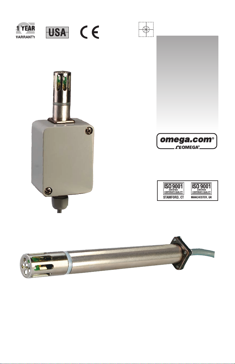
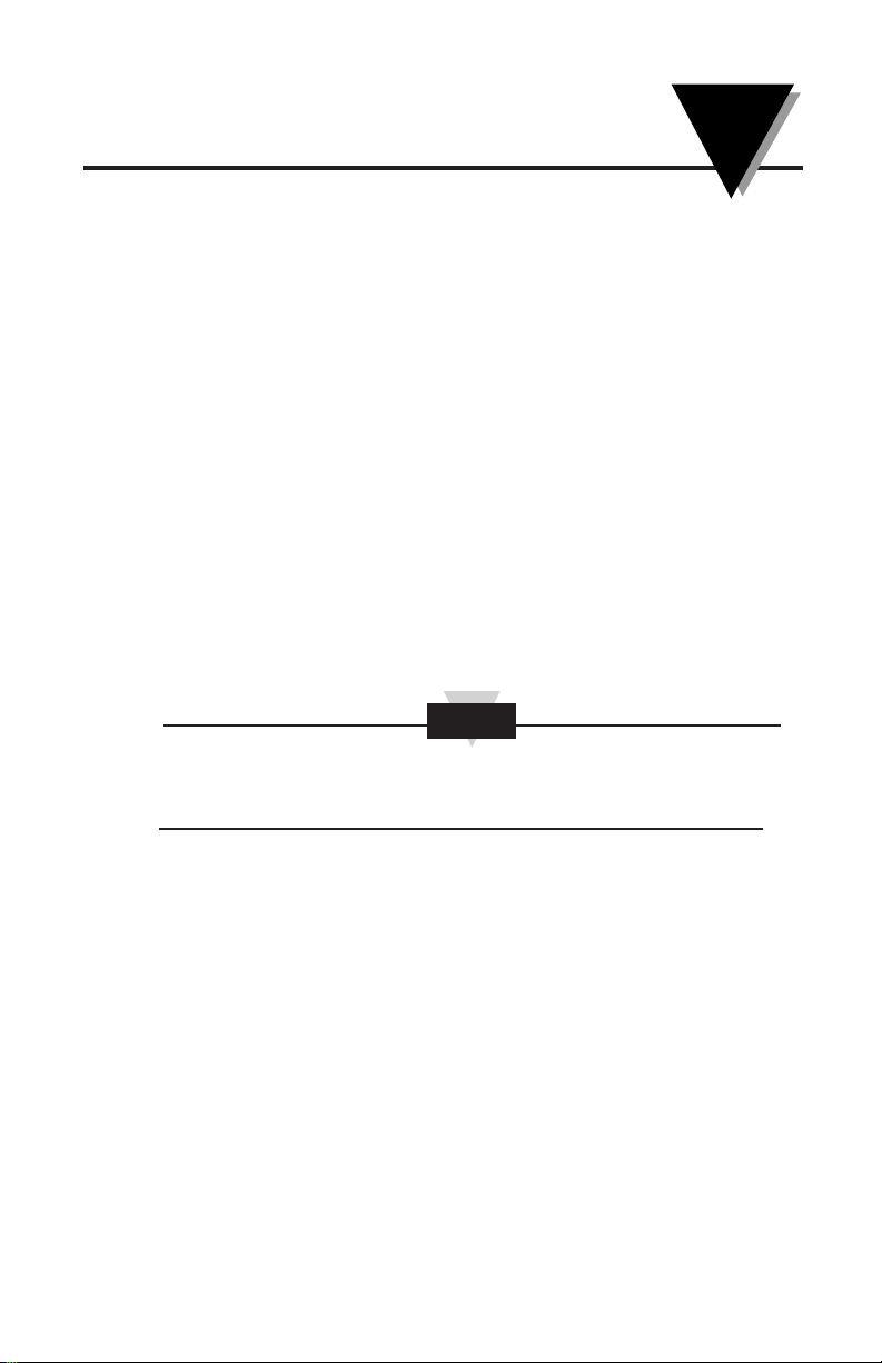
HX71 SERIES
RH Probe/Transmitter
User’s Guide
HX71-NB
MODEL
HX71 MODEL
Page 2

Servicing North America:
U.S.A.: Omega Engineering, Inc., One Omega Drive, P.O. Box 4047
ISO 9001 Certified
Stamford, CT 06907-0047
Toll-Free: 1-800-826-6342 Tel: (203) 359-1660
FAX: (203) 359-7700 e-mail: info@omega.com
Canada: 976 Bergar
Laval (Quebec), H7L 5A1 Canada
Toll-Free: 1-800-826-6342 TEL: (514) 856-6928
FAX: (514) 856-6886 e-mail: info@omega.ca
For immediate technical or application assistance:
U.S.A. and Canada: Sales Service: 1-800-826-6342/1-800-TC-OMEGA
®
Customer Service: 1-800-622-2378/1-800-622-BEST
®
Engineering Service: 1-800-872-9436/1-800-USA-WHEN
®
Mexico/ En Español: 001 (203) 359-7803 FAX: 001 (203) 359-7807
Latin America info@omega.com.mx e-mail: espanol@omega.com
Servicing Europe:
Benelux: Managed by the United Kingdom Office
Toll-Free: 0800 099 3344 TEL: +31 20 347 21 21
FAX: +31 20 643 46 43 e-mail: sales@omegaeng.nl
Czech Republic: Frystatska 184
733 01 Karviná, Czech Republic
Toll-Free: 0800-1-66342 TEL: +420-59-6311899
FAX: +420-59-6311114 e-mail: info@omegashop.cz
France: Managed by the United Kingdom Office
Toll-Free: 0800 466 342 TEL: +33 (0) 161 37 29 00
FAX: +33 (0) 130 57 54 27 e-mail: sales@omega.fr
Germany/Austria: Daimlerstrasse 26
D-75392 Deckenpfronn, Germany
Toll-Free: 0800 6397678 TEL: +49 (0) 7056 9398-0
FAX: +49 (0) 7056 9398-29 e-mail: info@omega.de
United Kingdom: OMEGA Engineering Ltd.
ISO 9001 Certified
One Omega Drive, River Bend Technology Centre, Northbank
Irlam, Manchester M44 5BD United Kingdom
Toll-Free: 0800-488-488 TEL: +44 (0) 161 777-6611
FAX: +44 (0) 161 777-6622 e-mail: sales@omega.co.uk
OMEGAnet®Online Service Internet e-mail
omega.com info@omega.com
It is the policy of OMEGA Engineering, Inc. to comply with all worldwide safety and EMC/EMI
regulations that apply. OMEGA is constantly pursuing certification of its products to the European New
Approach Directives. OMEGA will add the CE mark to every appropriate device upon certification.
The information contained in this document is believed to be correct, but OMEGA accepts no liability for any
errors it contains, and reserves the right to alter specifications without notice.
WAR NING: These products are not designed for use in, and should not be used for, human applications.
Page 3

TABLE OF
CONTENTS
HX71 SERIES
RH Probe/Transmitter
i
Section Page
1. General Description .................................................................... 1
2. Unpacking .................................................................................... 1
3. Theory of Operation ................................................................... 2
4. Installation and Mounting ..................................................... 3-4
5. Electrical Connections ................................................................ 5
6. Wiring Examples ........................................................................ 6
7. Relative Humidity Output Calculations ................................ 6
8. RH Measured Vs Output Reading Table ................................. 7
9. Calibration and Maintenance..................................................... 8
10. Specifications ............................................................................... 9
Page 4

FIGURES
HX71 SERIES
RH Probe/Transmitter
ii
Figure Page
Figure 1 Basic Transmitter Set-up
With Current Loop Output .............................................. 2
Figure 2 HX71 Dimensions .............................................................. 3
Figure 3 HX71 Mounting ................................................................ 3
Figure 4 HX71-NB Dimensions and Mounting ........................... 4
Figure 5 Current Transmitter Wiring Example
(4-20 mA) ............................................................................ 6
Figure 6 Voltage Transmitter Wiring Example
(0-1 Vdc and 0-5 Vdc) ....................................................... 6
Page 5
1
General Description
1
1. General Description
The OMEGA®HX71 Series Relative Humidity Transmitter’s provide a
linearized and temperature compensated output signal of 4 to 20 mA, 0 to
1 Vdc or 0 to 5 Vdc depending upon the model selected. The output signal
has been calibrated and scaled 0 to 100% for Relative Humidity. A thin film
polymer capacitor senses relative humidity and is protected by a stainless
steel cap that is easily removed for cleaning. The Nema-4 stainless steel
enclosure and cable entry connection provides weathertight protection.
2. Unpacking
Remove the packing list and verify that you have received all your
equipment. If you have any questions about the shipment, please call
our Customer Service Department at:
1-800-622-2378 or 203-359-1660. On the web you can find us at:
omega.com e-mail: cservice@omega.com
When you receive the shipment, inspect the container and equipment
for any signs of damage. Note any evidence of rough handling in
transit. Immediately report any damage to the shipping agent.
The carrier will not honor any damage claims unless all shipping material
is saved for inspection. After examining and removing contents, save
packing material and carton in the event reshipment is necessary.
The following items are supplied in the box with your HX71 transmitter.
• This Manual, # M-4543 (1 ea.)
• Dewpoint Card (1 ea.)
Recommended Power Supply
For HX71-MA and HX71-MA-NB, Omega Model PST-10
For HX71-V1, HX71-V2, HX71-V1-NB and HX71-V2-NB: Omega Model
FPW-15
Complimentary Instruments
iSeries
®
Panel Meters and Controllers
Recommended Accessories
Duct/Wall Mounting Kit, OMEGA®Part No.: HX70-MKIT (For HX71MA, HX71-V1, HX71-V2)
Transmitter Cable, OMEGA
®
Part No.: TX4-100 (100 ft)
RH Calibration Kit, OMEGA
®
Part No.: HX92-CAL
NOTE
Page 6

2
3. Theory of Operation
A 4-20 mA loop is a series loop in which a transmitter will vary the
current flow depending on the input to the transmitter. In the HX71
Series the amount of current allowed to flow in the loop will vary
depending on the relative humidity or temperature being measured by
the sensor(s). Some advantages of a current output over a voltage
output is that the signal measured is less susceptible to electrical noise
interference and the loop can support more than one measuring
instrument as long as the maximum loop resistance is not exceeded.
A typical application utilizing a current loop will normally consist of a
power supply, the transmitter and a meter, recorder or controller to
measure the current flow. The loop resistance in the sum of the
measuring instruments and wire used. The maximum allowable loop
resistance for the HX71 to function properly is found by using the
following formula:
R
max
= (power supply voltage – 8 volts) ÷ 0.02 amps
EXAMPLE: (When using a 10 Vdc power supply).
R
max
= (10 – 8) ÷ 0.02 amps = 800 ohms max loop resistance
Figure 1 - Basic Transmitter Set-up With Current Loop Output
3
Theory of Operation
HX71 CABLE
RED WIRE
SHIELD WIRE
BLACK WIRE
PANEL METER
POWER SUPPLY
+
10V
–
50%
+
–
Page 7

3
4. Installation and Mounting
Your HX71 Series RH Probe/Transmitter needs to be installed in
applications that allow for well circulated air flow to meet the published
specifications outlined here in this manual in Section 10.
OMEGA’s HX71 transmitter’s are designed for either wall or duct
mounting. A wall/duct mounting kit is available, OMEGA
®
Part
No.:HX90DM-KIT.
Figure 2 - HX71 Dimensions
Figure 3 - HX71 Mounting
131 (5.18)
R 16 (0.625)
DIMENSIONS: mm (in)
4
Installation and Mounting
HX71
MOUNTING BUSHING
MOUNTING SCREW
DUCT WALL
MOUNTING GASKET
MOUNTING PLATE
MOUNTING
NUT
MOUNTING
SCREW
HX71
CLAMP
NOTE
Page 8

4
Figure 4 - HX71-NB Dimensions and Mounting
4
Installation and Mounting
52.6 (2.07)
65 (2.56)
50 (1.97)
45.3 (1.78)
19.5
(0.76)
38 (1.50)
MOUNTING
HOLE
4.3 (0.17) DIA.
MOUNTING HOLE
4.3 (0.17) DIA.
16 (0.62) DIA.
DIMENSIONS: mm (in)
Page 9

5
5. Electrical Connections
All electrical connections and wiring should be performed by a suitably
trained professional only.
Model: HX71-MA, HX71-MA-NB
(2-Wire Current Output)
Red Wire: + Power Supply
Black Wire: 4-20 mA Output
Bare Wire: Shield, Earth Ground
Model: HX71-V1, HX71-V2, HX71-V1-NB, HX71-V2-NB
(3-Wire Voltage Output)
Red Wire: + Power Supply
Black Wire: - Power/-Output
Wire: + Output
White Bare Wire: Shield, Earth Ground
Your HX71 Series RH Probe/Transmitter has not been designed for, nor
is it recommended for, use in medical or nuclear applications.
Your HX71 Series RH Probe/Transmitter should never be installed in or
anywhere near explosive or flammable materials.
CAUTION
CAUTION
5
Electrical Connections
Page 10

6
6. Wiring Examples
Current output model HX71-MA, HX71-MA-NB (4 to 20 mA)
Figure 5 - Current Transmitter Wiring Example
Voltage output models HX71-V1, HX71-V2, HX71-V1-NB, HX71-V2-NB
(0 to 1 Vdc or 0 to 5 Vdc)
Figure 6 - Voltage Transmitter Wiring Example
7. Relative Humidity Output Calculations
To calculate % Relative Humidity by measuring the current or voltage
output use the following formulas.
For 4-20 mA output:
% RH = (Current measured in milliamps – 4) ÷ 0.16
EXAMPLE: (11.04 mA – 4) ÷ 0.16 = 44% RH
For 0 to 1 Vdc output:
% RH = (Voltage measured in volts x 100)
EXAMPLE: 0.44 Vdc x 100 = 44% RH
HX71 CABLE
RED WIRE
SHIELD WIRE
BLACK WIRE
PANEL METER
POWER SUPPLY
24V
50%
+
–
+
–
WHITE WIRE
HX71 CABLE
RED WIRE
SHIELD WIRE
BLACK WIRE
PANEL METER
POWER SUPPLY
+
10V
–
50%
+
–
6
HX71 SERIES
RH Probe/Transmitter
Page 11

7
8. RH Measured Vs Output Reading Table
% Relative
Output
Humidity 4-20 mA 0-1 (0-5) Vdc
5 4.8 0.05 (.25)
10 5.6 0.10 (.50)
15 6.4 0.15 (.75)
20 7.2 0.20 (1.00)
25 8.0 0.25 (1.25)
30 8.8 0.30 (1.50)
359.60.35 (1.75)
40 10.4 0.40 (2.00)
45 11.2 0.45 (2.25)
50 12.0 0.50 (2.50)
55 12.8 0.55 (2.75)
60 13.6 0.60 (3.00)
65 14.4 0.65 (3.25)
70 15.2 0.70 (3.50)
75 16.0 0.75 (3.75)
80 16.8 0.80 (4.00)
85 17.6 0.85 (4.25)
90 18.4 0.90 (4.50)
95 19.2 0.95 (4.75)
8
RH Measured Vs Output Reading Table
Page 12

8
9
Calibration and Maintenance
9. Calibration and Maintenance
Calibration
Your transmitter has been factory calibrated to meet or exceed the
specifications outlined in this manual. The economical design of the
HX71 Series does not allow for field adjustment. Contact our Customer
Service Department if you believe your unit is not functioning
correctly.
Maintenance
If your Humidity transmitter will be used in a dusty environment, the
protective sensor cover may be removed for cleaning. Unscrew the
protective cover and gently blow compressed air through the cap. A
soft brush may also be used to remove dirt particles.
If the sensor is subjected to 100% condensation, it must be dried to
obtain correct readings. There will be no permanent damage or
calibration shift to the unit.
Units should not be exposed to high concentrations of ammonia or
alcohol vapors.
Page 13

9
10. Specifications
Relative Humidity
Measuring Range: 5 - 95% (non-condensing)
Accuracy:* ±3.5% @ 22°C (72ºF) from 15 to 85% RH;
±4% @ 22°C (72ºF) below 15 and above
85% RH
* EMC (Electro Magnetic Compatibility)
Some of these devices may be subject to an additional reading error
of up to 2% by RFI (Radio Frequency Interference) when subjected to
a field strength of 3V/m between 625MHz and 725MHz.
Repeatability: ± 1% RH
Operating
Temperature Range: -25 to 85ºC (-13 to 185ºF)
Output:
Model HX71-MA,
HX71-MA-NB 4 to 20 mA (Scaled for 0 to 100% RH)
Model HX71-V1,
HX71-V1-NB 0 to 5 Vdc (Scaled for 0 to 100% RH)
Model HX71-V2,
HX71-V2-NB 0 to 1 Vdc (Scaled for 0 to 100% RH)
Power:
Model HX71-MA,
HX71-MA-NB 8 – 12 Vdc @ 20mA
Model HX71-V1, HX71-V2
HX71-V1-NB, HX71-V2-NB 8 – 24 Vdc @ 20mA
Max Loop Resistance: Ohms = (V supply – 8 V)/0.02 A
Sensor Type: Thin Film Polymer Capacitor
Enclosure Housing:
Tube Version: 316 Stainless Steel, NEMA 4
Enclosure Version: Polycarbonate, NEMA 4
Electrical Connections 2 m (6') 4-conductor shielded PVC
cable with stripped wire leads.
Dimensions: See “Mounting” Section
Weight: 200 g (7 oz)
Approvals: CE Marked
10
Specifications
Page 14

10
NOTES:
NOTES:
HX71 SERIES
RH Probe/Transmitter
Page 15

WARRANTY/DISCLAIMER
OMEGA ENGINEERING, INC. warrants this unit to be free of defects in materials and
workmanship for a period of 13 months from date of purchase. OMEGA’s WARRANTY adds
an additional one (1) month grace period to the normal one (1) year product warranty to
cover handling and shipping time. This ensures that OMEGA’s customers receive maximum
coverage on each product.
If the unit malfunctions, it must be returned to the factory for evaluation. OMEGA’s Customer
Service Department will issue an Authorized Return (AR) number immediately upon phone or
written request. Upon examination by OMEGA, if the unit is found to be defective, it will be
repaired or replaced at no charge. OMEGA’s WARRANTY does not apply to defects resulting
from any action of the purchaser, including but not limited to mishandling, improper
interfacing, operation outside of design limits, improper repair, or unauthorized modification.
This WARRANTY is VOID if the unit shows evidence of having been tampered with or shows
evidence of having been damaged as a result of excessive corrosion; or current, heat, moisture
or vibration; improper specification; misapplication; misuse or other operating conditions
outside of OMEGA’s control. Components in which wear is not warranted, include but are not
limited to contact points, fuses, and triacs.
OMEGA is pleased to offer suggestions on the use of its various products. However,
OMEGA neither assumes responsibility for any omissions or errors nor assumes
liability for any damages that result from the use of its products in accordance with
information provided by OMEGA, either verbal or written. OMEGA warrants only
that the parts manufactured by the company will be as specified and free of
defects. OMEGA MAKES NO OTHER WARRANTIES OR REPRESENTATIONS OF ANY
KIND WHATSOEVER, EXPRESSED OR IMPLIED, EXCEPT THAT OF TITLE, AND ALL
IMPLIED WARRANTIES INCLUDING ANY WARRANTY OF MERCHANTABILITY AND
FITNESS FOR A PARTICULAR PURPOSE ARE HEREBY DISCLAIMED. LIMITATION OF
LIABILITY: The remedies of purchaser set forth herein are exclusive, and the total
liability of OMEGA with respect to this order, whether based on contract, warranty,
negligence, indemnification, strict liability or otherwise, shall not exceed the
purchase price of the component upon which liability is based. In no event shall
OMEGA be liable for consequential, incidental or special damages.
CONDITIONS: Equipment sold by OMEGA is not intended to be used, nor shall it be used: (1)
as a “Basic Component” under 10 CFR 21 (NRC), used in or with any nuclear installation or
activity; or (2) in medical applications or used on humans. Should any Product(s) be used in or
with any nuclear installation or activity, medical application, used on humans, or misused in
any way, OMEGA assumes no responsibility as set forth in our basic WARRANTY/ DISCLAIMER
language, and, additionally, purchaser will indemnify OMEGA and hold OMEGA harmless from
any liability or damage whatsoever arising out of the use of the Product(s) in such a manner.
RETURN REQUESTS/INQUIRIES
Direct all warranty and repair requests/inquiries to the OMEGA Customer Service Department.
BEFORE RETURNING ANY PRODUCT(S) TO OMEGA, PURCHASER MUST OBTAIN AN
AUTHORIZED RETURN (AR) NUMBER FROM OMEGA’S CUSTOMER SERVICE DEPARTMENT
(IN ORDER TO AVOID PROCESSING DELAYS). The assigned AR number should then be
marked on the outside of the return package and on any correspondence.
The purchaser is responsible for shipping charges, freight, insurance and proper packaging to
prevent breakage in transit.
FOR WARRANTY
RETURNS, please have
the following information available BEFORE
contacting OMEGA:
1. Purchase Order number under which
the product was PURCHASED,
2. Model and serial number of the product
under warranty, and
3. Repair instructions and/or specific
problems relative to the product.
FOR NON-WARRANTY REPAIRS,
consult
OMEGA for current repair charges. Have the
following information available BEFORE
contacting OMEGA:
1. Purchase Order number to cover the
COST of the repair,
2. Model and serial number of theproduct, and
3. Repair instructions and/or specific problems
relative to the product.
OMEGA’s policy is to make running changes, not model changes, whenever an improvement is possible.
This affords our customers the latest in technology and engineering.
OMEGA is a registered trademark of OMEGA ENGINEERING, INC.
© Copyright 2010 OMEGA ENGINEERING, INC. All rights reserved. This document may not be copied, photocopied,
reproduced, translated, or reduced to any electronic medium or machine-readable form, in whole or in part, without
the prior written consent of OMEGA ENGINEERING, INC.
Page 16

M4543/0310
Where Do I Find Everything I Need for
Process Measurement and Control?
OMEGA…Of Course!
Shop online at omega.com
SM
TEMPERATURE
䡺⻬
Thermocouple, RTD & Thermistor Probes, Connectors, Panels & Assemblies
䡺⻬
Wire: Thermocouple, RTD & Thermistor
䡺⻬
Calibrators & Ice Point References
䡺⻬
Recorders, Controllers & Process Monitors
䡺⻬
Infrared Pyrometers
PRESSURE, STRAIN AND FORCE
䡺⻬
Transducers & Strain Gages
䡺⻬
Load Cells & Pressure Gages
䡺⻬
Displacement Transducers
䡺⻬
Instrumentation & Accessories
FLOW/LEVEL
䡺⻬
Rotameters, Gas Mass Flowmeters & Flow Computers
䡺⻬
Air Velocity Indicators
䡺⻬
Turbine/Paddlewheel Systems
䡺⻬
Totalizers & Batch Controllers
pH/CONDUCTIVITY
䡺⻬
pH Electrodes, Testers & Accessories
䡺⻬
Benchtop/Laboratory Meters
䡺⻬
Controllers, Calibrators, Simulators & Pumps
䡺⻬
Industrial pH & Conductivity Equipment
DATA ACQUISITION
䡺⻬
Data Acquisition & Engineering Software
䡺⻬
Communications-Based Acquisition Systems
䡺⻬
Plug-in Cards for Apple, IBM & Compatibles
䡺⻬
Data Logging Systems
䡺⻬
Recorders, Printers & Plotters
HEATERS
䡺⻬
Heating Cable
䡺⻬
Cartridge & Strip Heaters
䡺⻬
Immersion & Band Heaters
䡺⻬
Flexible Heaters
䡺⻬
Laboratory Heaters
ENVIRONMENTAL
MONITORING AND CONTROL
䡺⻬
Metering & Control Instrumentation
䡺⻬
Refractometers
䡺⻬
Pumps & Tubing
䡺⻬
Air, Soil & Water Monitors
䡺⻬
Industrial Water & Wastewater Treatment
䡺⻬
pH, Conductivity & Dissolved Oxygen Instruments
 Loading...