

Page 1
WARRANTY
_____,
~.
/
:
i
+
.
. . . . . i
Shop online a t
~mwf13m~
www.omega.com
info@omefla.com
e-mail:
HHT41
Portable Stroboscope
Page 2
(omega.com ”)
-
f’EOMEGA*-
OMEGAnet”
1
www.omega.co m
USA:
Is0
9001 Certified
- -
Cana.da:
For immediate technical or application assistance:
USA and Canada:
Mexko:
Benelux:
Czech Republic:
France:
GemlanylAustria:
United Kingdom:
x02
certified
Is0
- -
Online Service
Internet e-mail
info@omega.co m
Servicing North America:
One Omega
Stamford
Tel: (203) 359-1660 FAX: (203) 359-7700
e-mail:
Bergar
976
Tel: (514) 8566928 FAX: (514) 8566886
e-mail:
Sales Service:
Customer Service: l-800-622-2378
Engineering Service: l-800-872-9436
TELEX: 996484
Espariol: (001)
En
FAX:
Drive,
CT
06907-0047
info@omega.com
info@omega.ca
1-800-826-6342
203-359-7807
(801)
Box 4047
5A1,
H7L
Laval (Quebec)
EASYLINK
203-359-7803
Canada
l-SOO-TC-OMEGA@
/
/
l-800-622-BEST
1-8~USA-WHEN ’
/
62968934 CABLE: OMEGA
e-mail:
info@omega.com.mx
espanol@omega.com
Servicing Europe:
8034,llSO LA Postbus
Tel:
Toll Free in Benelux: 0800 0993344
sales@omegaeng.nl
e-mail:
Frystatska 184,733 01
Tel:
Toll Free: 0800-l-66342
11, rue Jacques
Tel:
Toll Free in France: 0800 466 342
e-mail:
Daimlerstrasse 26, D-75392 Deckenpfronn, Germany
Tel:
Toll Free in Germany: 0800 639 7678
e-mail:
One Omega Drive, River Bend Technology Centre
Northbank,
M44
Tel:
Toll Free in United Kingdom:
e-mail:
(0)59
+420
+33
sales@omega.fr
(0)7056
+49
info@omega.de
Irlam, Manchester
5BD United Kingdom
(0)161
+44
777 6611
sales@omega.co.uk
Amsteheen,
Karvina ’,
6311899
Cartier, 78280 Guyancourt, France
9398-O
The Netherlands
FAX:
Czech Republic
FAX:
e-mail:
FAX:
FAX:
0800-488-488
+31(0)20 6434643
+31(0)20 3472121
(0)59
+420
info@omegashop.cz
(0)130 57 54 27
+33
(0)l 61 37 29 00 FAX:
(0)7056
+49
(0)161777 6622
+44
6311114
939829
Gis
policy of OMEGA to comply with all worldwide safety and
apply. OMEGA is constantly pursuing certification of its products to the European New Approach
Directives. OMEGA will add the CE mark to every appropriate device upon certification.
The information contained in this document is believed
no liability for any errors it contains, and reserves the right to alter specifications without notice.
WARNING: These products are not designed for use in, and should not be used for, patient-connected applications.
correct, but OMEGA Engineering, Inc. to be
EMCiEMI regulations that
accepts
Page 3

1.0
SPECIFICATIONS
.......................................................................................
1
2.0
OVERVIEW
2.1
3.0
PREPARATION
3.1
3.2
4.0
OPERATION
4.1
4.2 External Mode
4.3
5.0
USING THE STROBOSCOPE TO MEASURE RPM
6.0
LAMP REPLACEMENT..
7.0
BATTERY PACK..
7.1
7.2
7.3
...............................................................................................
Display Panel
Power
I
Output Connections
Input
Internal Mode
Tach
Mode
Low Battery Indication.. .....................................................................
Charging the Battery Pack .................................................................
Battery Disposal
....................................................................................
FOR USE
................................................................................................
...............................................................................................
-
External Input Required..
.......................................................................................
..........................................................................
................................................................
-
Standard Strobe Operation
-
External Input Required
.............................................................................
................................................................................
........................................
............................................
...............................................
...................................
.2
3
.3
3
3
.4
.4
5
.5
.6
7
.8
.8
9
9
Page 4
!
A
1.
2.
3.
4.
5.
6.
, Safeguards and Precautions
Read and follow all instructions in this manual carefully,
and retain this manual for future reference.
Do not use this instrument in any manner inconsistent
with these operating instructions or under any
conditions that exceed the environmenta l
specifications stated.
Use of this product may induce an epileptic seizure in
persons prone to this type of attack.
Objects viewed with this product may appear to be
stationary when in fact they are moving at high speeds.
Always keep a safe distance from moving machinery
and do no touch the target.
Thlere
are lethal voltages present inside this product.
Refer to the section on Lamp Replacement before
attempting to open this product.
Do not allow liquids or metallic objects to enter the
ventilation holes on the stroboscope as this may cause
permanent damage and void the warranty.
1
.
A
7.
ThIis
product contains a sealed lead acid battery which
must be disposed of in accordance with Federal, State
and Local Regulations. Do not incinerate. Batteries
should be shipped to a reclamation facility for recovery
of the metal and plastic components as the proper
method of waste management. Refer to section 7.3 of
this manual, and contact your distributor for appropriate
product return procedures.
a.
This instrument is not user serviceable. For technical
assistance, contact the sales organization from which
you purchased the product.
Page 5
1 .O SPECIFICATIONS
Internal Mode:
Flash Range
Flash Rate Accuracy
Flash Rate Resolution (Setting)
Display Update Rate
External Mode:
Flash Range and Display
FPM Accuracy
Display Update Rate
Trigger to Flash Delay
External Input
Tachometer
Tachometer
Tachometer Accuracy
Display Update
External
Time Base
Display
Indicators
Adjustment
Memory
output
Power
Light
Flash Duration
Run Time
Weight
IWode:
kleasurements
lnpul
PUISC!
Power
Rate
Stable Crystal Oscillator
6-digit alphanumeric backlit LCD display with 0.3 inch
Low Battery, On Target Indicator, Locked On, External Mode, Tachometer
Mode,
12
Four Quadrant Pressure Sensitive Tuner Button with decade select for flash rate
up or down, multiply by 2 and divide by 2
Saves eight programmable flash rates and last flash rate at power down
350
Removable 6 Vdc Rechargeable Battery Pack with Integral Electronics Charge
Control for rechargers
300mA)
150
10
1
hour typical at
1.4 Ibs
x2
psec positive pulse, 5 Vdc typical
- 30 microseconds typical
[0.63
-
12,500 FPM (Flashes per Minute)
100
The greater
0.1 FPM
Continuous
5.0
The greater of
1
second typical
< 5
0 to 5 volt TTL Compatible
20
5 to 250,000 RPM
The greater of
1 second typical
0 to 5 volt TTL Compatible
5
psec tnin pulse width, Positive edge triggered
1800
kg] including Battery Pack
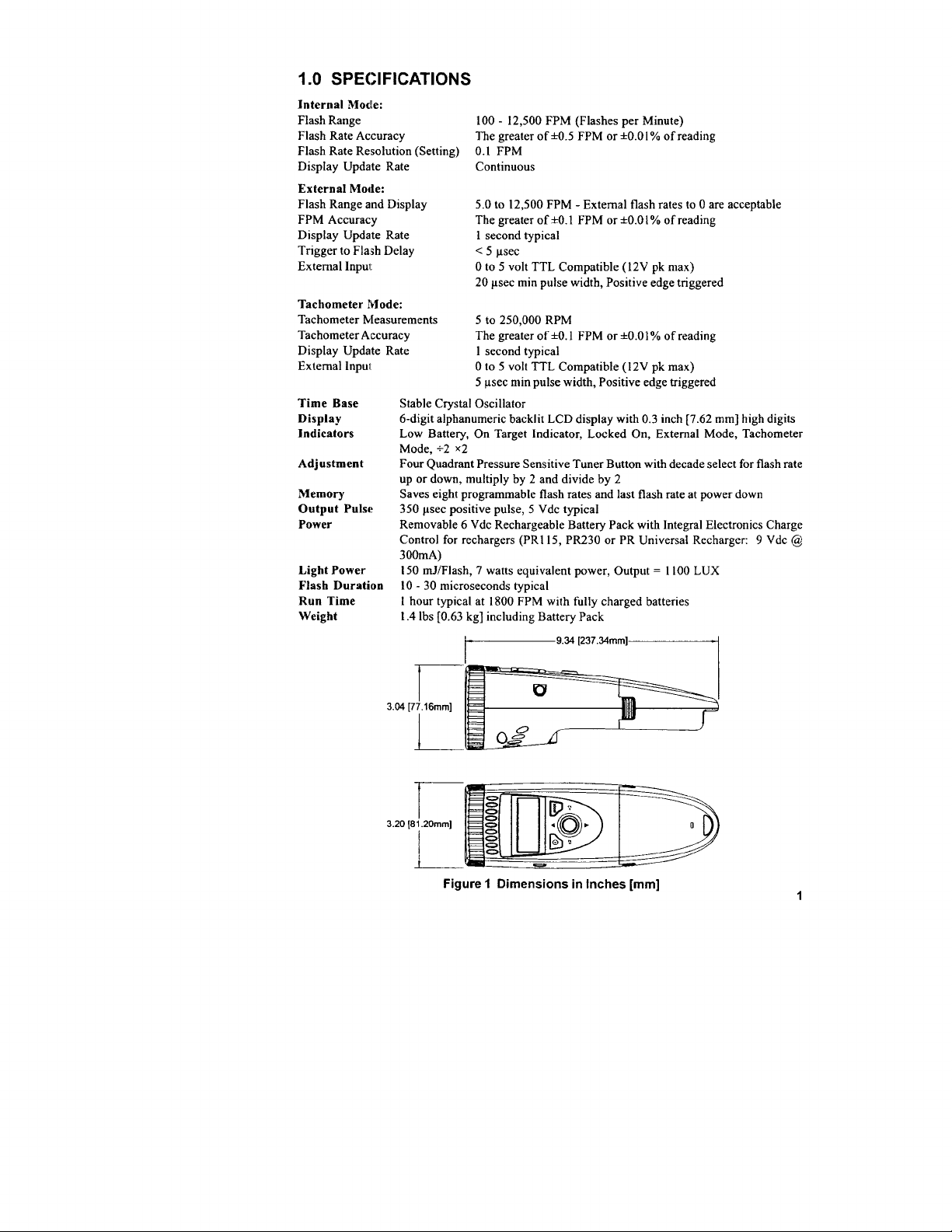
t-9.34
ofh0.5
to
12,500
FPM
*to.1
psec
psec
min pulse width, Positive edge triggered
*O.
1 FPM or
(PRI 15, PR230 or PR Universal Recharger: 9 Vdc
equivalent power, Output = 1100 LUXmJ/Flash, 7 watts
FPM with fully charged batteries
*O.OI%
FPM or
- External flash rates to 0 are acceptable
FPM or
iO.Oi% of reading
(12V pk max)
iO.Ol% of reading
(12V
[237.34mm]-1
of reading
pk max)
[7.62
mm] high digits
@
3.04
3.20
r-
[77.16mm]
i.
l--
[61.20mm]
L-
Figure 1 Dimensions in Inches [mm]
Page 6

2.0 OVERVIEW
HtiT41
The
a pocket-size, lightweight, industrial strength, single-handed operation instrument that fits in the
palm of your hand. A four Quadrant Pressure Sensitive Tuner Button adjusts the flash rate, and
provides multiply or divide by 2 functions. A large, bright, backlit, 6-digit alphanumeric LCD
display shows the flash rate and mode of operation.
flash rate settings and the last used setting in non-volatile memory, so that the unit “remembers” all
the flash rates when the power is turned off. The pulse
external input up to the maximum FPM. The Tachometer mode will measure rotational speed up to
250,000 RPM with an optional Self-Powered Sensor.
The Strobe has a removable, rechargeable Battery Pack which provides up to 1 hour of continuous
use depending on the flash rate. This Battery Pack clips in and out with no tools required. An
optional second Battery Pack allows for longer operation in the field. A
on the underside of the Strobe allows for tripod mounting. The Strobe can be locked “ON” for hands
free operation.
is a sophisticated stroboscope with many features, yet remains simple to operate. It is
The Strobe can store and recall eight programmable
output
phone jack connector will accept an
‘h-20
UNC thread bushing
Connector
2
Power Button
Battery Pack
Figure 2 HHT41
Multiple features of HHT41 are patent pending.
\
Battery
Recharger
Socket
Page 7

Dis;play Panel
2.1
EX T
Figure 3 Display Panel
dispilay
The
which indicate modes, flash rates, etc. (see Figure 3).
Other icons or messages in the display indicate the following:
panel consists of a backlit, liquid crystal display with six alphanumeric digits
f.Yl
:;
TACH
+2
Displayed when the battery is getting low. There is protection circuitry in the
unit that will prevent the battery
from being operated with a low battery.
On Target Indicator for Tachometer Mode and Remote Sensor in External Mode
Shown on the display when the Strobe is locked on.
Shown on the display when the Strobe is in the External Mode.
Shown on the display when the Strobe is in the Tachometer Mode.
*:2
When this icon is shown on the display, rocking the tuning button to the left
will divide the current flash rate by two and rocking the tuning button to the
right will multiply the current flash rate by two.
TACH
+2x2
from being over discharged or prevent the unit
3.0 PREPARATION FOR USE
HHT41
may be hand held or mounted on a tripod or other user supplied bracket using the
UNC bushing in the base of the unit.
Power
3.1
HHT41
has a removable lead acid Battery Pack that clips in and out
The
Batt’ery
continuously in excess of 55 minutes at 1800 flashes per minute from fully charged batteries.
The Strobe has a protection feature that prevents the Strobe from operating if the battery
voltage is low. This condition is indicated by no flash and the Low Battery icon (
displayed (see section 7.1). At this time the Battery Pack must be recharged or a fully charged
Battery Pack can be plugged in as a substitute. The actual operating time of the stroboscope
depends on the flash rate and duty cycle of operation. Slower flash rates increase the operating
time.
3 . 2
HHT41
(3.5 mm) stereo phone plug and can be used for external triggering or synchronization of the
stroboscope or for providing a pulse output, synchronous with the flash. The jack ’s outer
Pack should be charged before use (see section 7.0).
1
Output Connections
lnplut
has an input /output jack on the side of the stroboscope. This jack accepts a
ofthe
HHT41
I
s-20
main strobe housing.
will operate
m)
will be
l/8 inch
3
Page 8

connection (barrel) is
common, the inner or
center connection is the
signal, and the tip is the
pulse output (see Figure
4). The input and output
are TTL compatible.
With no external input the
Strobe provides a TTL
compatible pulse output
fmm
the Strobe ’s internal oscillator.
input pulse.
Figure 4 Input/Output Connector Detail
Ifan
external input is applied, the output pulse mimics the
Common
@ND)
Signal Input
Signal Output
4.0 OPERATION
To turn on the stroboscope, press and release the
and hold the On/Off
release the button. Press and release the On/Off
When the Strobe is powered up, it will begin flashing immediately at the last internal flash rate
displayed. The last digit changed will flash for 5 seconds allowing the digit to be changed again. Rock
the tuning button up or down to change the flashing digit. Rock the tuning button left or right to
select a different digit to change.
The flash rate is displayed on the LCD display in flashes per minute, which typically is the same
as RPM.
The
HT41
H
x2, Recall and Store) that are adjusted by the MODE button. By default, the Strobe powers up in
the Internal Mode. Pressing the MODE button will change the
+2
applicable to the Internal Mode.
In the
Internal Mode,
number of Flashes Per Minute (FPM or RPM).
another strobe or a remote self-powered sensor is used to trigger the flash and the tuner button has
no effect. In the
powered) sensor as RPM up to
I
Internal Mode
4.
In the Internal Mode
frequency variable speed signals and functions like a typical
stroboscope. This is the default start up mode.
The rubber tuning button functions as a multi dimensional
joystick. The tuning button is sensitive in four linear xy
quadrants, and also senses pressure in the z-plane. Place
your thumb on the button and use a rocking motion
(forward, back, or side-to-side) to control it (see Figure 5).
The harder you apply pressure, the faster the rate of
increase. It is
increments with very slight finger pressure.
(0)
button until the Locked icon
has three primary operating modes (Internal, External and
the tuner button adjusts the flash rate from the minimum to the maximum
Tach
Mode
the unit will not flash, but will display the input
250,000
-
Standard Strobe Operation
the stroboscope generates it ’s own
to
possible
adjust the Strobe in 0.1 FPM
OniOlT(@) button. To lock the power
(0)
is displayed (about 2 seconds) and then
(a)
button again to turn the Strobe off.
modelfirnction in the following order:
x2, Recall and Store functions are only
-2
Tach, Internal. The x2, Recall, Store, External,
In
the External Mode, an external signal from
RPM.
and three functions
Figure 5 Tuning button
on; press
(+2Tach)
(self-from an external
Page 9

To change the flash rate:
1.
Press the tuning button. The last digit changed will begin blinking.
2.
Rock the tuning button to the
is the one to be changed.
3.
Rock the tuning button up or down to increase or decrease the value of the blinking digit.
The digit will stop blinking after 5 blinks and the Strobe will continue to flash at the new
flash rate.
To
multiply or divide
1.
Press the MODE button once. The
2.
Rock the tuning button to the left for
down while
3.
Repeat steps 1 and 2 each time you want to multiply or divide the flash rate.
NCYTEZ
the current flash rate by 2:
+2
in
the
Ifa
multiply or divide operation will exceed the limits of the unit, upper limit or
lower limit, the display will indicate
left or right to select which digit to change. The digit blinking
+2
~2 icon will be displayed.
X2.
x2 Mode will have no effect.)
+2 or right for
(Rocking the hitting button up or
OVER or UNDER and no change will be
made to the flash rate.
To
select a flash rate from a Preset (memory) location:
2.
Press the MODE button again (without pressing the rubber tuning button in between).
“RECALL” will be displayed.
3.
Rock the tuning button up or down to select a preset flash rate. The display will show
MEMX”, where X=the present location
location and begin flashing at the specified flash rate with each press of the button.
4.
Press the MODE button to return to the Internal Mode using the selected flash rate.
To store the current flash rate in a Preset (memory) location:
Pre.ss
the MODE button once. The
Pre:;s
the MODE button a second time (without pressing the rubber tuning button in
between). “RECALL” will be displayed.
Pre:rs
the MODE button again (without pressing the rubber tuning button in between).
“STORE” will be displayed.
Rock the tuning button up or down to select the location in which to store the current flash
rate. The display will show
display the flash rate saved in that location.
Once you have selected a preset location to overwrite, press the MODE button to save the
5.
current flash rate in that location. “SAVING” will be displayed and theu you will return to
the Internal Mode.
4.2
External Mode
Press the MODE button (without pressing the tuning button in between) until the
displayetl. An external input is required (TTL compatible source from a self-powered sensor).
External
In the
triggered by the input signal. This mode is used to synchronize
(for example, from an optical sensor) to stop or freeze motion for timing studies or balancing
machine,;. The flash will be triggered on the rising edge of the external input pulse.
The maximum input is 12,500 FPM, above which the Strobe will no longer flash.
Tach
4.3
Press the MODE button (without pressing the tuning button in between) until the
is displayed. In the
(self-powered sensor) and display the reading on the LCD display, without flashing the lamp.
The Strobe can read up to 250.000 RPM in this mode.
Mode
- External Input Required
Mode
there are no flash rate adjustments the user can make. The flash rate is
-
External Input Required
Tachometer
+2 I. Press the MODE button once. The
~2 icon will be displayed.
(l-8),
and then display the flash rate saved in that
+2
~2 icon will be displayed.
MEMX”, where X=the present location “S
the flash to an external event
Mode the unit will read the signal from the external input
(l-8),
and then
EXT
TACH
“R
icon is
icon
5
Page 10

5.0 USING THE STROBOSCOPE TO MEASURE RPM
prtmary use for a stroboscope is to stop motion for diagnostic inspection purposes. However,
The
the stroboscope can also be used to measure speed.
considered. First, the object being measured should be visible for all 360” of rotation (e.g. the end of
a
shaft:l.
Second, the object should have some unique part on it. like a bolt, key way or imperfection
to use as a reference point. If the object being viewed is perfectly symmetrical, then the
to mark the object with a piece of tape or paint in a single location, while the object is stationary, to
be used as a reference point.
If the speed ofrotation is within the range of the stroboscope, start at the highest flash rate and adjust
the flash rate down. At some point you will stop the motion with only a single image of the object
in view. Note that at a flash rate twice the actual speed of the image you will see two images.
approach the correct speed you may see three, four or more images at harmonics
The
fir:st
SINGLE image you see is the true speed. To confirm the true speed, note the reading and
adjust the stroboscope to exactly half this reading, or just press the left of the joystick button for the
+2
function. You should again see a single image (which may be phase shifted with respect to the
first image seen).
For example, when viewing a shaft with a single key way, you will see one stationary image of the
key way at the actual speed and at
key
wa:y
at 2 times the actual speed. 3 key way images at 3 times, etc. (see Figure 6).
Minute (FPM) equals the shaft ’s Revolutions Per Minute (RPM) at the highest flash rate
that gives only one stationary image of the key way.
l/2,1/3.1/4, etc, of the actual speed. You will see 2 images of the
In order to do this,
severai factors need to be
user
needs
As you
ofthe
actual speed.
The Flash Per
i”:
Stopped Image
Flash Rate (FPM)
If the speed is outside the full scale range
the method of harmonics and multipoint calculation. Start at the highest flash rate and adjust the
flash rate down. Be aware that you will encounter multiple images. Note the flash rate of the
SINGLE image you encounter, and call this speed “A”. Continue decreasing the flash rate until you
encounter a second SINGLE image. and note this speed as “B”. Continue decreasing the speed until
you reach a third SINGLE image at speed “C”.
For a two point calculation the actual speed is given by:
For a three point calculation: RPM =
Sell‘-Powered
If a
display directly in RPM (FPM) without any adjustment required.
In
instalnces
tachoms-ter
as an optical tachometer.
down the device.
when the flash rate is slower than 300 FPM. Therefore, a stroboscope image is
300
6
when you can shut down the device and install a piece ofreflective tape, then an optical
is easier to use for RPM
FPM
for inspection or to measure RPM.
OO.I=I
6.0 LAMP REPLACEMENT
WARNING:
strobosco,pe is designed to discharge the internal high voltages within 30 seconds. However,
The
caution should be exercised when replacing the lamp.
To
change the lamp it is necessary only to remove the Front lens, which is held in place by the rubber
bumper. Pry the rubber bumper off the end of the unit. The reflector is held in place by the front lens
and will come loose, but is not necessary to remove the reflector. Hold the lamp with a cloth between
your forefinger and thumb and rock it back and forth gently while pulling out. Do not attempt to
rotate the lamp. The lamp is socketed and will come out easily when pulled.
WARNING:
lalnps
The
to hold the
rock the lamp back and forth while pushing it into place (see Figure 7). Make sure the lamp
straight and centered in the reflector
Before attempting to remove the lamp, make sure the stroboscope is
turned off and remove the Battery Pack (see section 7.0). Allow the lamp
to cool, waiting at least
Do NOT touch the new lamp with bare fingers.
are polarized and must be put into the socket matching polarity. Using
lalmp,
match up the red dot on the plug with the red dot on the socket and gently
hole.
1
minute.
a
lint free
cloth
is in
Figure
7 Lamp Replacement
Reinstall the
with the two small tabs on the housing to prevent lens rotation (see Figure 7). Stretch the rubber
bumper over the top and bottom case halves to seal in the reflector and front lens.
reflector and then position the front
lens in place matching up the notches on the lens
dots
7
Page 12

IBATTERY
7.0
The Battery Pack can be removed by pressing the two latches on either side of the unit while gently
pulling the Battery Pack outwards (see Figure 8). To install the Battery Pack, slide it into the Strobe
until you hear the side latches engage and lock. Match the top and bottom colors when inserting the
Battery Pack into the Strobe. The Battery Pack is keyed so that it can not be inserted into the Strobe
upside down.
CAUTION:
PACK
The terminals on the Battery Pack are recessed. DO NOT SHORT THESE
CONNECTIONS. There is a non-serviceable internal resettable fuse
for protection.
NOTE:
Press both sides
to release
Figure 8 Battery Pack Removal
7.1 Low Battery Indication
When the batteries are low, the Low Battery icon
used
for a short time. When the battery charge is further depleted, the Strobe will stop flashing,
the Low Battery icon (
When the Low Battery icon (
section 7.2).
NCTB
If the batteries are discharged you will not be able to run the unit. The unit may not
start at all, or the Low Battery icon (
shut off. Recharge the Battery Pack or replace it with a fully charged unit.
0
) will be displayed, and then the Strobe will completely shut off.
a
) is displayed, the Battery Pack needs to be recharged (see
Match top and bottom case
colors when sliding Battery
Pack into the Strobe.
I
Installation
(0)
is displayed. The Strobe may still be
03)
may be displayed and then the Strobe will
Page 13

7.2 Charging
Battery Pack may be recharged at any time. You do not need to wait until the low battery
The
condition is indicated. The Battery Pack does not need to be in the Strobe for charging.
To charge the Battery Pack:
1.
2.
3.
NOTE:
The battery module contains circuitry to control the charge. The red LED comes on to indicate
that the battery is being charged.
recharger will trickle charge the battery. The Battery Pack may be used at this point.
NOTE:
7.3
Battery Disposal
Prior to disposing of the Battery Pack, the user must remove the sealed lead acid battery. To do
this, remove the four screws on the under side of the Battery Pack and separate the case halves,
exposing the battery. Remove the cables from the battery and place tape over the battery
terminals to prevent them from shorting. The battery should be sent to a recycling center or
returned to the factory. The rest of the parts may now be disposed of.
the Battery Pack
Make sure the Strobe is off or remove the Battery Pack from the Strobe.
Plug the recharger cable into the battery recharger socket on the Battery Pack (see
Figure 2 for location).
Plug the recharger into
When using the
plug is inserted into the recharger before plugging the recharger
into the wall outlet.
230RC or
warranty.
The total charge time is typically 6 to 8 hours. The Battery Pack may be left on
trickle charge indefinitely.
an
AC mains wall outlet.
HHT4lURC
other
URC)
HHT41
Once the charge is completed, the LED turns
recharger, make sure the correct adapter
than
the one supplied CAUTIGN: Use of rechargers
may damage the stroboscope and void the
(HHT41-115RC,
amber
HHT41-
and the
Page 14

WARRANTY/DISCLAIMER
OMEGA ENGINEERING, INC. warrants this unit to be free of defects in materials and
workmanship for a period of 13
additional one (1) month grace period to the normal one (1) year
handling and shipping time. This ensures that OMEGA ’s customers receive maximum
coverage on each product.
If
the unit malfunctions, it must be returned to the factory for evaluation. OMEGA ’s Customer
Service Department will issue an Authorized Return (AR) number immediately upon phone or
written request. Upon examination by OMEGA, if the unit is found to be defective, it will be
repaired or replaced at no charge. OMEGA ’s WARRANTY does not apply to defects resulting
from any action of the purchaser, including but not limited to mishandling, improper interfacing,
operation outside of design limits, improper repair, or unauthorized modification. This
WARRANTY is VOID if the unit shows evidence of having been tampered with or shows evidence
of having been damaged as a result of excessive corrosion; or current, heat, moisture or vibra-
tion; improper specification; misapplication; misuse or other operating conditions outside of
OMEGA’s control. Components which wear are not warranted, including but not limited to
contact points, fuses, and
irr
OMEGA
OMEGA
provided
manufactured by it
WARRANTIES OR REPRESENTATIONS OF ANY KIND WHATSOEVER, EXPRESS OR
WARRANlY
HEREBY
berein
based on
not
shall
CONDITIONS: Equipment sold by OMEGA is not intended to be used, nor shall it be used:
a “Basic Component” under 10 CFR 21 (NRC), used in or with any nuclear installation or activity;
or (2) in medical applications or used on humans. Should any Product(s) be used in or with any
nuclear installation or activity, medical application, used on humans, or misused in any way,
OMEGA assumes no responsibility as set forth in our basic WARRANTY/DISCLAIMER language,
and,
or damage ‘whatsoever arising out of the
pleased to offer suggestions on the
neither
assumes
any
damages that for
Iby
OMEGA, either verbal or written. OMEGA
IEXCEPT
THAT OF TITLE, AND ALL IMPUED,
MERCHANTABiUrY
OF
O%CLAIMED.
exdusive.
am
exoeedl the
OMEGA be liable for
additic’nally,
and the total riri of OMEGA
cxmtract
warranty.
purchase
purchaser will indemnify OMEGA and hold OMEGA harmless from any liability
months
triacs.
rerponsibiiit~
result
from
specified
UMiTATlON
negrit3ce.
ef
price
conseqwntial,
from date of purchase. OMEGA ’s Warranty adds an
use
of its various products. However,
em&ions
anY
for
of its products in accordance with information
the use
of defects. OMEGA MAKES NO OTHER
free
and will be es
AND
OF LIABILITY:
the component
incidental or special damages.
use
IMPUED
FlTNESS
FOR A
The
with
indemnificatien.
upon
of the Product(s) in such a manner.
product warranty
emns nor assumes
01
warrents only that the parts
WARRANTlES
remedii
respect to
sttict
wbiih
riri is based. In no event
INCLUDING ANY
PARllCUlAR
of
purchaser set forth
tbii
ribiri of
to cover
IiiitY
PURPOSE
order, whether
othewke.
ARE
shall
(1)
as
Direct all warranty and repair requests/inquiries to the OMEGA Customer Service Department.
RETURN REQUESTS/INQUIRIES
BEFORE RETURNING ANY PRODUCT(S) TO OMEGA, PURCHASER MUST OBTAIN AN
AUTHORIZED RETURN (AR) NUMBER FROM OMEGA ’S CUSTOMER SERVICE DEPARTMENT
(IN ORDER TO AVOID PROCESSING DELAYS). The assigned AR number should then be
marked on the outside of the return package and on any correspondence.
The purchaser is responsible for shipping charges, freight, insurance and proper packaging to
prevent
bre,skage
FOR
WARRANTY
the following information available BEFORE
contacting OMEGA:
1. Purchase Order number under which
the product was PURCHASED,
2. Model and serial number of the product
under warranty, and
3. Repair instructions and/or specific
problems relative to the product.
OMEGA ’s
This affords our customers the latest in technology and engineering.
OMEGA is a
Q Copyright
reproduced, translated, or reduced to any electronic medium or machine-readable form, in whole or in pert, without
the prior written consent of OMEGA ENGINEERING, INC.
in transit.
RETURNS, please have
1s
to make running changes, not model changes, whenever an improvement is possible.
pohcy
ree@fered
trademark of OMEGA ENGINEERING. INC.
2C’O3
OMEGA ENGINEERING, INC. All rights reserved. This document may not be copied, photocopied,
FOR NON-WARRANTY REPAIRS, consult
OMEGA for current repair charges. Have the
following information available BEFORE
contacting OMEGA:
1. Purchase Order number to cover the
COST of the repair,
2. Model and serial number of the
product, and
3. Repair instructions and/or specific problems
relative to the product.
Page 15

Wlhere
Do I Find Everything I Need
fbr
Process Measure ment and Control?
OMEGA ...Of
Shop online at
Course !
www.omega.com
TEMPERATURE
&
G?
Thermocouple, RTD
@
Wire: Thermocouple, RTD
0’ Calibrators
153
Recorders, Controllers
Ii3
Infrared Pyrometers
&
Ice Point References
PRESSURE, STRAIN
0
Transducers
I&?
Load Cells
@’
Displacement Transducers
@’
Instrumentation
&
&
Pressure Gages
Thermistor Probes, Connectors, Panels
&
Thermistor
&
Process Monitors
AND FORCE
Strain Gages
&
Accessories
FlOW/LEVEL
[a
Rotameters, Gas Mass
Gf Air Velocity Indicators
ia
Turbine/Paddlewheel Systems
Total&m
li3
&
Batch Controllers
pH/CONDUCTIVITY
&
li3
@’
Benchtop/Laboratory Meters
&
m
Industrial
pH
AccessoriespH Electrodes, Testers
Conductivity Equipment
DATA ACQUISITION
Ii??’
Data Acquisition &Engineering Software
@
Communications-Based Acquisition Systems
p
Plug-m Cards for Apple, IBM
Gl’
Datalogging Systems
0
Recorders, Printers
&
&
Plotters
&
Flow ComputersFlowmeters
&
PumpsGf Controllers, Calibrators, Simulators
Compatibles
&
Assemblies
HEATERS
@
Heating Cable
G?
Cartridge
k?
Immersion
lZf
Flexible Heaters
&I’
Laboratory Heaters
&
Strip Heaters
&
Band Heaters
ENVIRONMENTAL
MON lTORlNG
k?
Metering&Control Instrumentation
J&’
Refractometers
Gt’
Pumps &Tubing
0’ Air, Soil &Water Monitors
B
Industrial Water
@
AND CONTROL
&
Wastewater Treatment
&
Dissolved Oxygen InstrumentspH, Conductivity
M3855/0103
 Loading...