

Page 1
User’s Guide
omega.com
®
www.omega.com
e-mail: info@omega.com
™
HHP-401 Series
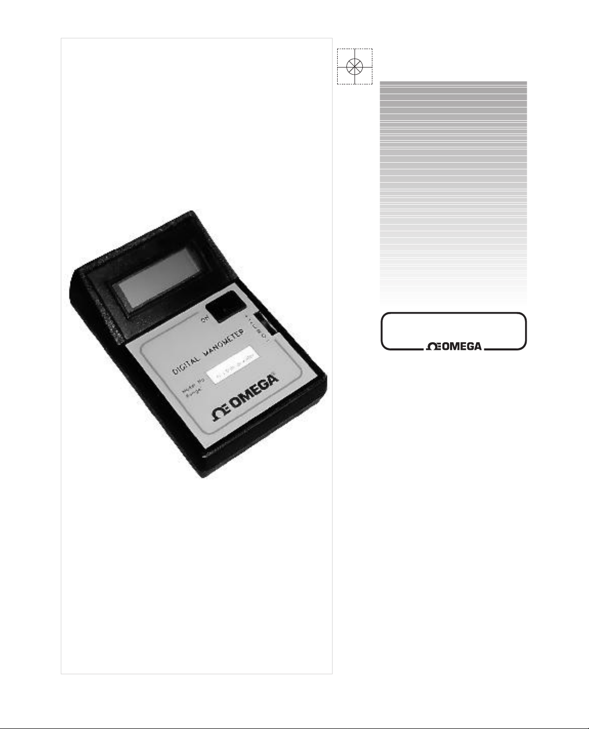
Digital Manometer
Page 2

Servicing North America:
USA: One Omega Drive, P.O. Box 4047
ISO 9001 Certified Stamford CT 06907-0047
TEL: (203) 359-1660 FAX: (203) 359-7700
e-mail: info@omega.com
Canada: 976 Bergar
Laval (Quebec) H7L 5A1
TEL: (514) 856-6928 FAX: (514) 856-6886
e-mail: info@omega.ca
For immediate technical or application assistance:
USA and Canada: Sales Service: 1-800-826-6342 / 1-800-TC-OMEGA
®
Customer Service: 1-800-622-2378 / 1-800-622-BEST
®
Engineering Service: 1-800-872-9436 / 1-800-USA-WHEN
®
TELEX: 996404 EASYLINK: 62968934 CABLE: OMEGA
Mexico: Tel: (001) 800-826-6342 FAX: (001) 203-359-7807
En Espan˜ol: (001) 203-359-7803 e-mail: espanol@omega.com
info@omega.com.mx
Servicing Europe:
Benelux: Postbus 8034, 1180 LA Amstelveen, The Netherlands
TEL: +31 (0)20 6418405 FAX: +31 (0)20 6434643
Toll Free in Benelux: 0800 0993344
e-mail: nl@omega.com
Czech Republic: Rudé armády 1868, 733 01 Karviná
TEL: +420 (0)69 6311899 FAX: +420 (0)69 6311114
Toll Free in Czech Rep.: 0800-1-66342 e-mail: czech@omega.com
France: 9, rue Denis Papin, 78190 Trappes
TEL: +33 (0)130 621400 FAX: +33 (0)130 699120
Toll Free in France: 0800-4-06342
e-mail: france@omega.com
Germany/Austria: Daimlerstrasse 26, D-75392 Deckenpfronn, Germany
TEL: +49 (0)7056 3017 FAX: +49 (0)7056 8540
Toll Free in Germany: 0800 TC-OMEGA
SM
e-mail: germany@omega.com
United Kingdom: One Omega Drive, River Bend Technology Centre
ISO 9002 Certified Northbank, Irlam, Manchester
M44 5EX, United Kingdom
TEL: +44 (0)161 777 6611 FAX: +44 (0)161 777 6622
Toll Free in the United Kingdom: 0800 488 488
e-mail: sales@omega.co.uk
omega.comomega.com
OMEGAnet®On-Line Service Internet e-mail
www.omega.com info@omega.com
It is the policy of OMEGA to comply with all worldwide safety and EMC/EMI regulations that
apply. OMEGA is constantly pursuing certification of its products to the European New Approach
Directives. OMEGA will add the CE mark to every appropriate device upon certification.
The information contained in this document is believed to be correct, but OMEGA Engineering, Inc. accepts
no liability for any errors it contains, and reserves the right to alter specifications without notice.
WARNING: These products are not designed for use in, and should not be used for, patient-connected applications.
®
™
Page 3

DIGITAL MANOMETER, HHP-401 Series
Specifications
Ranges, in inches of water column : .1", .2", .5", 1.0", 2.0", 5.0", 10.0"
Accurracy +/- 1% of range plus 1 digit
Resolution .001" for ranges to 1.0", .01" for ranges from 2.0" to 10.0"
Connections Metal fittings for 3/32" or 3/16" flexible tubing
Display LCD, .5" digit height
Low battery indicator The symbol "BAT" appears on display
Battery One 9 Volts, alkaline
Battery life 200 hours
Operating temperature range0o
Storage temperature
Standard accessories 9V batter y
Optional accessories Carrying case with two lengths of rubber tubing, one
Warning: This device is for use with air or non corrosive, non explosive gases only.
Warning: Care should be taken not to exceed the maximum overpressure.
Maximum Safe Momentary Overpressure Table
Range Overpressure
English Metric English Metric
0.100 - 1.00" H2O 25 to 250 Pa 8" H2O2 kPa
2.00 - 10.0" H2O 0.5 to 2.5 kPa 5 psid 35 kPa
11.00" H2O - 5 psid 2.7 to 35 kPa 20 psid 140 kPa
C to +50oC (+32oF to +122oF)
-20oC to +70oC (-4oF to +160oF)
insertion tube, two static pressure tips, one 6 " insertion
length Pitot tube. Longer Pitot tubes to 60" are available
General instructions
1) Turn manometer on.
2) If low battery signal is displayed, replace battery located in compartment on back of
manometer.
3) Turn zero adjustment thumbwheel until display indicates zero.
4) Manometer is now ready to operate. Use as follows:
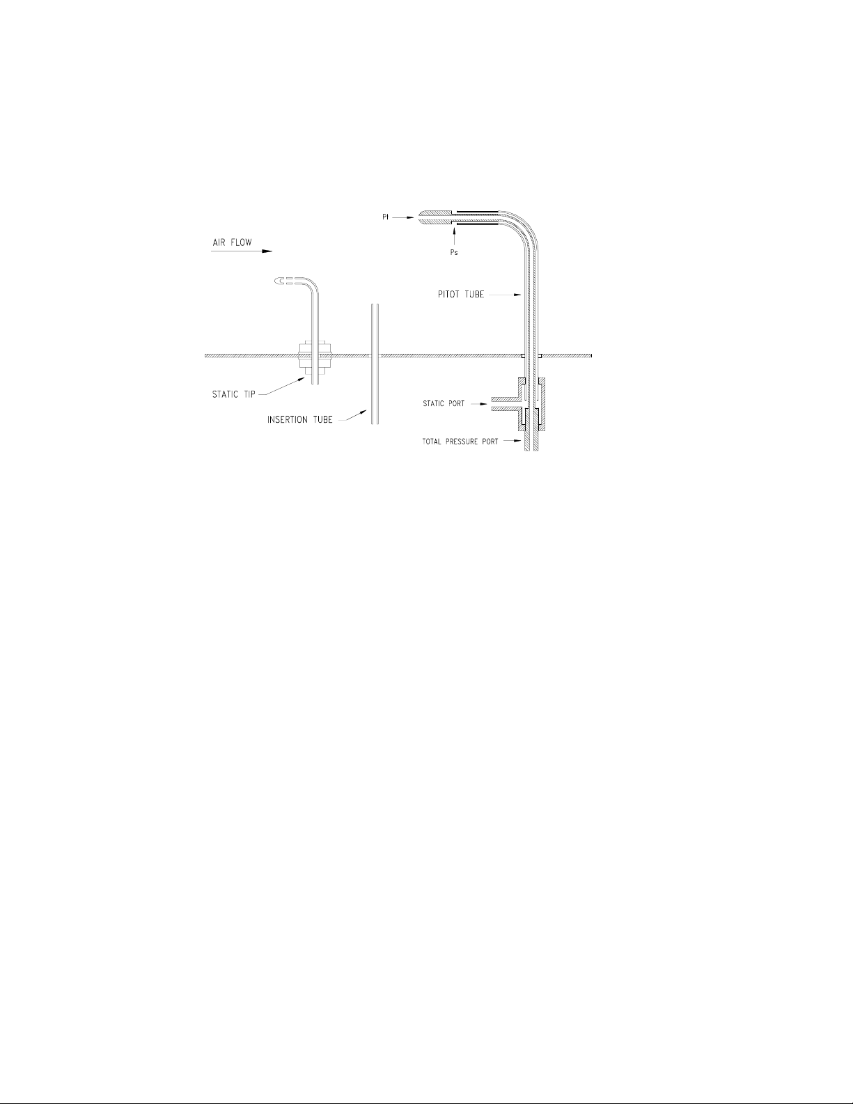
Static pressure
For measurements of static pressure in d ucts, it is recommended that a static pressure t ip or the
static connection of a Pitot tube be used (see f ig.1). Run tubing from stat ic tip to high pressure
port of manometer. A positive readin g i ndica tes pr es sur e a bov e atm os pheric pr ess ur e; a neg ativ e
reading, a pressure below atmospheric pressure.
Insertion tube
The insertion tube may be used to measure static pressure wher e flow is re latively s low, smooth
and without turbulence. The op eni ng of th e tu be must be perpendicular to the direc ti on of t he f low
(see fig.1). If turbulenc e exists, impingement, aspir ation or unequal distribut ion of moving air at
the opening can reduce accuracy of readings significantly.
Air filter test
Connect manometer diff erentially across filter w ith static tips pointin g upstream to eliminat e the
possibility of error due t o air velocity. Connect the tubing fr om the static tip downstream of the
HHP-401 M-3490 / 0899
Page 4
filter to the low pressure port of the manometer and the tu bing from t he static tip u pstream of the
filter to the high pressure port of the manometer.
Figure 1
Air velocity measurement
1) Connect total pressure port (Pt) of Pi tot tube to high pressure por t of manometer and static
port (Ps) to low pressure port to read velocity pressure.
2) Insert Pitot tube in duct with tip pointing upstream and make a traverse according to fig. 2.
Refer to chart of fig. 3 to determine air velocity for each traverse point at standard conditions
70oF and 29.92 inches of mercury barometric pressure with a resulting density of .075
Lb/cu.ft) or use following formulas to compute air velocity at conditions other than standard.
The velocities are then averaged.
Note - For very small r ound pipes, a center reading is freque ntly sufficient to o btain reasonable
accuracy. For ducts 6 to 10 inches in dia meter an d average v elocities of 1000 t o 3000 f t/min, the
center velocity pressur e r e ading may be mu ltiplied by .81 to obtain the average velocity pr es sur e.
This method is not recommended for either accurate results or very high (or low) velocities.
HHP-401 M-3490 / 0899
Page 5

Note - Install a straightener at 6 duct diameters downstream from the beginning of straight portion
of duct and take velocity pressure reading 7 1/2 duct diameters downs-tream from the beginning of
this straight portion to insure correct P itot tube readings.
Air velocity = 1096.2 Pv where Pv = velocity pressure, in inches of water
D D = air density, in Lb/cu.ft
Air density = 1.325 Pb where Pb = barometric pressure in inches of mercury
460 +
To determine air flow : Q = AV where Q = flow, in cu.ft. per min.
o
F
o
F = temperature in degrees Farenheit
A = duct area, in square ft.
V = velocity, in ft. per min.
Note - For rectangular ducts, divide up the total area into a large number of small equal areas and
take a velocity pressure reading in the center of each small area. The number o f readin gs should
not be less than 16 and need not be more than 64. When less than 64 read ings are taken, the
number of equal spaces shou ld be such t hat the ce nters of the areas ar e not mor e than 6 inc hes
apart.
VELOCITY PRESSURE, Inches of water
0.00 0.01 0.02 0.03 0.04 0.05 0.06 0.07 0.08 0.09
400 566 694 801 896 981 1060 1133 1202
.0 .1 .2 .3 .4 .5 .6 .7 .8 .9
0
1
2
3
4
5
6
7
8
9
10
4003 4198 4385 4564 4736 4902 5063 5219 5370 5517
5661 5801 5937 6070 6201 6329 6454 6577 6698 6816
6933 7048 7160 7271 7381 7488 7595 7699 7803 7905
8006 8105 8203 8300 8396 8491 8585 8678 8770 8860
8950 9039 9128 9215 9302 9387 9472 9556 9640 9723
9805 9886 9967 10047 10126 10205 10283 10361 10438 10514
10590 10666 10741 10815 10889 10962 11035 11107 11179 11251
11322 11392 11462 11532 11601 11670 11738 11806 11874 11941
12008 12075 12141 12207 12272 12337 12402 12467 12531 12594
12658 12721 12784 12846 12909 12970 13032 13093 13154 13215
1266 1790 2192 2532 2830 3101 3349 3580 3707
Figure 3 – Velocities (ft/min) for dry air at various pressures
o
@70
F and 29.92 inches of Hg barometric pressure
HHP-401 M-3490 / 0899
Page 6

WARRANTY/DISCLAIMER
OMEGA ENGINEERING, INC. warrants this unit to be free of defects in materials and workmanship for a
period of 13 months from date of purchase. OMEGA’s Warranty adds an additional one (1) month grace
period to the normal one (1) year product warranty to cover handling and shipping time. This
ensures that OMEGA’s customers receive maximum coverage on each product.
If the unit malfunctions, it must be returned to the factory for evaluation. OMEGA’s Customer Service
Department will issue an Authorized Return (AR) number immediately upon phone or written request.
Upon examination by OMEGA, if the unit is found to be defective, it will be repaired or replaced at no
charge. OMEGA’s WARRANTY does not apply to defects resulting from any action of the purchaser,
including but not limited to mishandling, improper interfacing, operation outside of design limits,
improper repair, or unauthorized modification. This WARRANTY is VOID if the unit shows evidence of
having been tampered with or shows evidence of having been damaged as a result of excessive corrosion;
or current, heat, moisture or vibration; improper specification; misapplication; misuse or other operating
conditions outside of OMEGA’s control. Components which wear are not warranted, including but not
limited to contact points, fuses, and triacs.
OMEGA is pleased to offer suggestions on the use of its various products. However,
OMEGA neither assumes responsibility for any omissions or errors nor assumes liability for any
damages that result from the use of its products in accordance with information provided by
OMEGA, either verbal or written. OMEGA warrants only that the parts manufactured by it will be
as specified and free of defects. OMEGA MAKES NO OTHER WARRANTIES OR
REPRESENTATIONS OF ANY KIND WHATSOEVER, EXPRESS OR IMPLIED, EXCEPT THAT OF TITLE,
AND ALL IMPLIED WARRANTIES INCLUDING ANY WARRANTY OF MERCHANTABILITY AND FITNESS FOR A PARTICULAR PURPOSE ARE HEREBY DISCLAIMED. LIMITATION OF
LIABILITY: The remedies of purchaser set forth herein are exclusive, and the total liability of
OMEGA with respect to this order, whether based on contract, warranty, negligence,
indemnification, strict liability or otherwise, shall not exceed the purchase price of the
component upon which liability is based. In no event shall OMEGA be liable for
consequential, incidental or special damages.
CONDITIONS: Equipment sold by OMEGA is not intended to be used, nor shall it be used: (1) as a “Basic
Component” under 10 CFR 21 (NRC), used in or with any nuclear installation or activity; or (2) in medical
applications or used on humans. Should any Product(s) be used in or with any nuclear installation or
activity, medical application, used on humans, or misused in any way, OMEGA assumes no responsibility
as set forth in our basic WARRANTY/DISCLAIMER language, and, additionally, purchaser will indemnify
OMEGA and hold OMEGA harmless from any liability or damage whatsoever arising out of the use of the
Product(s) in such a manner .
RETURN REQUESTS / INQUIRIES
Direct all warranty and repair requests/inquiries to the OMEGA Customer Service Department. BEFORE
RETURNING ANY PRODUCT(S) TO OMEGA, PURCHASER MUST OBTAIN AN AUTHORIZED RETURN
(AR) NUMBER FROM OMEGA’S CUSTOMER SERVICE DEPARTMENT (IN ORDER TO AVOID
PROCESSING DELAYS). The assigned AR number should then be marked on the outside of the return
package and on any correspondence.
The purchaser is responsible for shipping charges, freight, insurance and proper packaging to prevent
breakage in transit.
FOR W
ARRANTY RETURNS, please have the
following information available BEFORE
contacting OMEGA:
1. Purchase Order number under which the product
was PURCHASED,
2. Model and serial number of the product under
warranty, and
3. Repair instructions and/or specific problems
relative to the product.
FOR NON-WARRANTY REPAIRS,
consult OMEGA
for current repair charges. Have the following
information available BEFORE contacting OMEGA:
1. Purchase Order number to cover the COST
of the repair,
2. Model and serial number of the product, and
3. Repair instructions and/or specific problems
relative to the product.
OMEGA’s policy is to make running changes, not model changes, whenever an improvement is possible. This affords
our customers the latest in technology and engineering.
OMEGA is a registered trademark of OMEGA ENGINEERING, INC.
© Copyright 1999 OMEGA ENGINEERING, INC. All rights reserved. This document may not be copied, photocopied,
reproduced, translated, or reduced to any electronic medium or machine-readable form, in whole or in part, without the
prior written consent of OMEGA ENGINEERING, INC.
MADE IN
Page 7

Where Do I Find Everything I Need for
Process Measurement and Control?
OMEGA…Of Course!
TEMPERATURE
MU
Thermocouple, RTD & Thermistor Probes, Connectors, Panels & Assemblies
MU
Wire: Thermocouple, RTD & Thermistor
MU
Calibrators & Ice Point References
MU
Recorders, Controllers & Process Monitors
MU
Infrared Pyrometers
PRESSURE, STRAIN AND FORCE
MU
Transducers & Strain Gages
MU
Load Cells & Pressure Gages
MU
Displacement Transducers
MU
Instrumentation & Accessories
FLOW/LEVEL
MU
Rotameters, Gas Mass Flowmeters & Flow Computers
MU
Air Velocity Indicators
MU
Turbine/Paddlewheel Systems
MU
Totalizers & Batch Controllers
pH/CONDUCTIVITY
MU
pH Electrodes, Testers & Accessories
MU
Benchtop/Laboratory Meters
MU
Controllers, Calibrators, Simulators & Pumps
MU
Industrial pH & Conductivity Equipment
DATA ACQUISITION
MU
Data Acquisition & Engineering Software
MU
Communications-Based Acquisition Systems
MU
Plug-in Cards for Apple, IBM & Compatibles
MU
Datalogging Systems
MU
Recorders, Printers & Plotters
HEATERS
MU
Heating Cable
MU
Cartridge & Strip Heaters
MU
Immersion & Band Heaters
MU
Flexible Heaters
MU
Laboratory Heaters
ENVIRONMENTAL
MONITORING AND CONTROL
MU
Metering & Control Instrumentation
MU
Refractometers
MU
Pumps & Tubing
MU
Air, Soil & Water Monitors
MU
Industrial Water & Wastewater Treatment
MU
pH, Conductivity & Dissolved Oxygen Instruments
HHP-401 Series M3490 / 0899
 Loading...