

Page 1
omega.com
e-mail: info@omega.com
For latest product manuals:
omegamanual.info
User’s Guide
HHP350 SERIES
High Accuracy Manometer
Shop online at
MADE IN
Page 2

Servicing North America:
U.S.A.:
OMEGA Engineering, Inc.
ISO 9001 Certified
One Omega Drive, P.O. Box 4047
Stamford, CT 06907-0047 USA
Toll-Free: 1-800-826-6342 TEL: (203) 359-1660
FAX: (203) 359-7700 e-mail: info@omega.com
Canada:
976 Bergar
Laval (Quebec), Canada H7L 5A1
Toll-Free: 1-800-826-6342 TEL: (514) 856-6928
FAX: (514) 856-6886 e-mail: info@omega.ca
For immediate technical or application assistance:
U.S.A. and Sales Service: 1-800-826-6342/1-800-TC-OMEGA
®
Canada: Customer Service: 1-800-622-2378/1-800-622-BEST
®
Engineering Service: 1-800-872-9436/1-800-USA-WHEN
®
Mexico:
En Espan˜ol: 001 (203) 359-7803 FAX: (001) 203-359-7807
info@omega.com.mx e-mail: espanol@omega.com
Servicing Europe:
Benelux: Managed by the United Kingdom Office
Toll-Free: 0800 099 3344 TEL: +31 20 347 21 21
FAX: +31 20 643 46 43 e-mail: sales@omega.nl
Czech Republic: Frystatska 184
733 01 Karviná, Czech Republic
Toll-Free: 0800-1-66342 TEL: +420-59-6311899
FAX: +420-59-6311114 e-mail: info@omegashop.cz
France:
Managed by the United Kingdom Office
Toll-Free: 0800 466 342 TEL: +33 (0) 161 37 29 00
FAX: +33 (0) 130 57 54 27 e-mail: sales@omega.fr
Germany/Austria:
Daimlerstrasse 26
D-75392 Deckenpfronn, Germany
Toll-Free: 0 800 6397678 TEL: +49 (0) 7059 9398-0
FAX: +49 (0) 7056 9398-29 e-mail: info@omega.de
United Kingdom:
OMEGA Engineering Ltd.
ISO 9001 Certified
One Omega Drive, River Bend Technology Centre
Northbank , Irlam, Manchester M44 5BD England
Toll-Free: 0800-488-488 TEL: +44 (0)161 777-6611
FAX: +44 (0)161 777-6622 e-mail: sales@omega.co.uk
OMEGAnet®On-Line Service Internet e-mail
omega.com info@omega.com
It is the policy of OMEGA Engineering, Inc. to comply with all worldwide safety
and EMC/EMI regulations that apply. OMEGA is constantly pursuing
certification of its products to the European New Approach Directives. OMEGA
will add the CE mark to every appropriate device upon certification.
The information contained in this document is believed to be correct, but
OMEGA accepts no liability for any errors it contains, and reserves the right
to alter specifications without notice.
WARNING: These products are not designed for use in, and should not be
used for, human applications.
Page 3

USER MANUAL
SMART MANOMETER
The Smart Manometer products are microcontroller based
pressure sensing devices used to directly measure pressure.
Differential, Gauge, Absolute and Wet/Wet pressure sensors
are supported (see Specification section for supported types
and pressure ranges). Pressure can be displayed in selectable
engineering units of measure.
Features include Min/Max capture, display Hold, sensor Zero,
Leak Test, Record/View (up to 240 points), user selectable
damping and field recalibration. The manometer is powered
by four AA alkaline batteries for more than 100 hours of use.
Page 1 of 28
Page 4

Table of Contents
User Interface ............................................................3
Keypad Functions..................................................3
On/Off & Backspace
MIN/MAX & UP
HOLD & DOWN
PRGM & ENTER
Key ............................... 3
Arrow Key......................... 3
Arrow Key ........................3
Key ...................................4
BACKLIGHT KEY............................................. 4
Zeroing the Manometer .......................................5
Program Mode..................................................... 5
Units Select ...........................................................6
User Unit Select ....................................................7
Flow Unit Select.................................................... 8
Damp Rate Select .................................................. 8
User Info Select...................................................10
Auto Shut-Off......................................................11
Lockout Select..................................................... 12
Header Name.......................................................13
Contrast Select..................................................... 14
Data Logging....................................................... 15
Leak Test............................................................. 16
Re-Calibration ..................................................... 17
RE-CALIBRATION – 1 Point EDIT & START 18
RE-CALIBRATION – 5 Point EDIT ..................19
RE-CALALIBRATION – 5 Point START .........19
RE-CALIBRATION – Restore Factory Defaults 21
Specifications .......................................................... 22
Certification/Safety/Warnings ................................. 24
Changing the Batteries.............................................24
User Connections.....................................................26
Contact Information.................................................28
Page 2 of 28
Page 5
User Interface
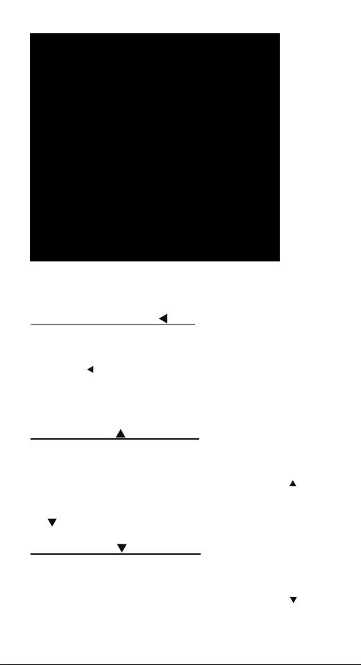
1. Keypad Functions
ON/OFF & BACKSPACE
Turns the manometer on and enters the unit into the Measure
Mode. Pressing the key while in the Measure Mode turns the unit
off. It also serves as a backspace key when editing in the Program
Mode. The
without changing the previous setting. Pressing this key repeatedly
will return the user to the Measure Mode and then shut off the
manometer.
MIN/MAX & UP
In the Measure Mode activates the Min/Max function of the
manometer. When activated the minimum value is displayed on the
upper left of the display and the maximum value on the upper right.
This key also deactivates and resets this function. The
used to scroll through the programmable registers when the unit is
in the Program Mode. Once a programmable register is selected
the
HOLD & DOWN
In the Measure Mode toggles on/off the display Hold function.
This freezes the value displayed. If the MIN/MAX function is
activated, those values are also frozen. With HOLD activated, the
letter “H” appears in the lower left of the display. The
used to scroll through programmable registers with the unit in the
key takes the user out of a programmable register
ARROW KEY
key can be used to edit that register.
KEY
key is
ARROW KEY
key is
Page 3 of 28
Page 6

Program Mode. Once a programmable register is selected the
key can be used to edit that register.
PRGM & ENTER
Puts the manometer into the Program Mode from the Measure
Mode. When in the Program Mode, pressing this key selects the
programmable register to be edited (with prompt for password if
Lockout is set). After the register has been edited, pressing the
PRGM key enters the new setting into the manometer’s nonvolatile memory. This key also acts as a
input such as the header name and user units.
BACKLIGHT KEY
The BACKLIGHT key, represented by the standard light bulb
symbol, toggles the display backlight between green and off.
KEY
key when editing user
Page 4 of 28
Page 7

2. Zeroing the Manometer
To zero the manometer, first turn off pressure sources and vent
pressure ports to atmosphere. The display should read close to zero.
Press the MIN/MAX and HOLD keys at the same time and then
release. This begins the zeroing process. The top line of the display
reads “ZERO IN PROGRESS” while the bottom line counts down
from 9. The process is complete when the unit returns to Measure
Mode. The lockout function, if enabled, does not interfere with the
zeroing of the manometer.
Note: The Smart Manometer can only be zeroed if the new zero
value is within +/-5% (of FS) of the original factory calibrated zero.
If the zero procedure generates a new zero value outside this limit
a “ZERO RANGE ERROR” message appears indicating that the
procedure failed.
3. Program Mode
The program mode is used to configure the manometer for
Measure Mode operation. After the PRGM key is pressed in
Measure Mode, the top line of the display reads “PROGRAM
MODE”. The bottom line reads “UNITS SELECT”. Press the
arrow keys to scroll through the Program Mode to the desired
register. The configurable registers that are found in Program
Mode are Units Select, Damp Rate Select, User Info Select,
Contrast Select, Data Logging, Leak Test and Exit. Two sub-
modes under “Units Select” are provided: User Unit Select and
Flow Unit Select. Press the PRGM key to select either of these
sub-modes and set up their respective function. The manometer
can be put into Program Mode at any time during Measure Mode
operation by pressing the PRGM key. If Lockout is set, the correct
code must be entered when prompted.
or
Page 5 of 28
Page 8
Units Select
The standard engineering units available on the Smart Manometer
are:
PSI
inH
0 (@20°C, 60°F and 4°C)
2
2
Kg/cm
kPa
mbars
Bars
cmH
O (@ 20°C)
2
inHg (@ 0°C)
mmHg (@ 0°C)
User Units
Flow Units
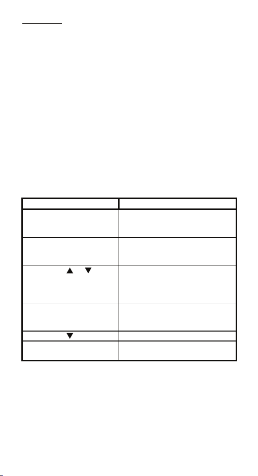
To change the engineering units the manometer should be “ON”
and in Measure Mode. Then follow these steps:
Keystroke Display
1. Press the PRGM key. Top line reads “PROGRAM
MODE” and bottom line reads
“UNITS SELECT”.
2. Press the PRGM key. Top line reads “UNITS
SELECT” and bottom line shows
current engineering units.
3. Press the or arrow
key until desired
Engineering units on bottom line
of display change.
engineering unit is
displayed.
4. Press the PRGM key to
select the engineering unit.
Top line reads “PROGRAM
MODE” and bottom line reads
“UNITS SELECT”.
5. Press the arrow key. Bottom line reads “EXIT”.
6. Press the PRGM key. Display returns to Measure Mode
in new engineering units.
Page 6 of 28
Page 9
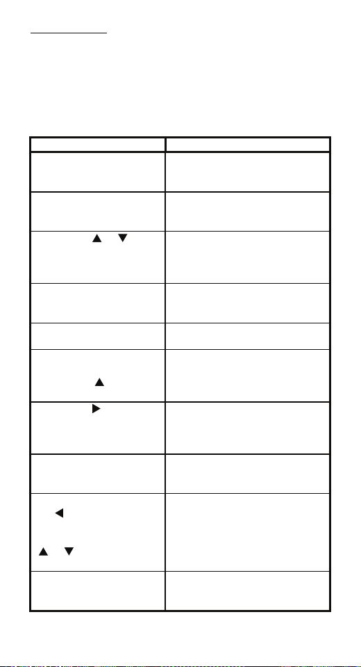
User Unit Select
Engineering units not included in the standard selection can be
programmed into the manometer using the Units Select register in
the program mode. The value programmed into this register is
used to calculate the desired unit of measure. An example of
converting to “Feet of H2O” will be shown in the following steps,
using the conversation factor of 1 PSI = 2.30894 FT H2O.
Keystroke Display
1. Press the PRGM key. Top line reads “PROGRAM
2. Press the PRGM key. Top line reads “UNITS
3. Press the or arrow
key until “USER UNIT
SELECT” is displayed.
4. Press the PRGM key.
See note 1 at bottom of
this table.
5. Press the PRGM key to
change the value.
6. Start entering the
conversion factor by
pressing the
until the first digit reads 2.
7. Press the arrow key
to enter the value “2” and
advance the cursor to the
next digit.
8. Repeat step 6 and 7
until bottom line reads
2.30894
9. If an error is made use
the
the cursor back to the
incorrect digit. Then press
or arrow keys to
display the correct value.
10. Press the PRGM key
until the display changes.
See note 1 at bottom of
arrow key
arrow key to move
MODE” and bottom line reads
“UNITS SELECT”.
SELECT” and bottom line shows
current engineering units.
Top line reads “UNITS
SELECT”
Bottom line reads “USER UNIT
SELECT”.
Top line reads “VALUE=”.
Bottom line reads “CHANGE?:
YES”.
Top line reads “USER UNIT
VALUE”.
Top line reads “USER UNIT
VALUE”.
Bottom line reads “20000000”.
Cursor flashes to the right of the
“2”. Now numbers, decimal
point or blank space can be
entered.
Bottom line reads “2.30894”.
Last digit “4” is blinking.
The digit that is corrected is
blinking.
Top line reads “VALUE=”.
Bottom line reads “CHANGE?:
YES”.
Page 7 of 28
Page 10

this table.
11. Press the PRGM key. Top line reads “USER UNIT
NAME”.
12. Follow steps 6-8
above to enter “FT H2O”.
Bottom line reads “FT H2O”.
Last letter “O” is blinking.
13. Press the PRGM key. Top line reads “PROGRAM
MODE”.
Bottom line reads “UNITS
SELECT”.
14. Press the arrow
Bottom line reads “EXIT”.
key.
15. Press the PRGM key. Manometer returns to Measure
Mode. Units Display shows “FT
H2O”.
Note 1: If at steps 4 or 10 the “VALUE=” is the desired value,
press the
or arrow key. This will toggle the bottom line from
the default “CHANGE?: YES” to “CHANGE?: NO”. Step 5
would then jump to step 10. Step 11 would then jump to step 13.
Flow Unit Select
Smart Manometers that use differential pressure sensors can be
programmed to read out flow measurement units such as CFM or
L/min. The primary element must be a differential pressure square root type device such as a pitot tube, orifice plate or venturi.
The flow constant and flow units description are programmed into
the manometer using the same keystrokes used in the User Unit
Select programming. At step 3 choose “FLOW UNIT SELECT”
instead of “USER UNIT SELECT”.
Calculate the Flow constant from the following equation:
F
= Q ÷ DP
c
½
where: Fc = Flow constant
Q = Flow rate
(from flow element calculation sheet)
DP = Differential pressure corresponding to Q
Example: If the DP is 25 units when the flow rate is 10,000 units,
then the Flow constant is 2,000.
Damp Rate Select
Adjustable exponential type damping is available to steady the
display when measuring pulsating pressure or flow. The Smart
Manometer has a range of damping rates; 0.1, 0.2, 0.5, 1, 2, 5, 10,
or 25 seconds. Exponential damping shows approximately 70% of
a step change in pressure upon the next display update. When set
Page 8 of 28
Page 11

for 5 second time constant, it takes 5 seconds from the time of the
step change until the manometer displays the full value of the new
pressure.
To set the damp rate:
Keystroke Display
1. Follow the steps on
page 4 to put the unit in
Program Mode
2. Press the arrow
key.
Top line reads
PROGRAM MODE” and
bottom line reads “UNITS
SELECT”.
Bottom line reads “DAMP
RATE SELECT”.
3. Press the PRGM key. Top line reads “DAMP
4. Press the or
arrow key until the
desire desired damp rate
is displayed on the
bottom line.
5. Press the PRGM key. Top line reads
6. Press the arrow
key.
7. Press the PRGM key. Returns to Measure Mode.
RATE SELECT”.
Bottom line shows damp
rate in seconds.
“PROGRAM MODE” and
bottom line reads “UNITS
SELECT”.
Bottom line reads
“EXIT”.
Page 9 of 28
Page 12

User Info Select
The User Info Select registers are designed to provide the user with
information on the hardware and software in the manometer. This
register provides read only information on the sensor’s serial
number, software version and date of manufacture. It also allows
the user to edit the Auto Shut-Off, Lockout and Start-Up Header
Name features.
To configure the User Info Select registers follow the steps shown
on the following page.
Keystroke Display
1. From the Measure Mode
press the PRGM key.
2. Press the arrow key
twice
3. Press the PRGM key. Bottom line shows serial
4. Press the arrow key. Software version number
5. Press the arrow key. Manufacture date shown.
6. Press the arrow key.
Instructions to set AUTO
SHUT-OFF are in this
manual.
7. Press the arrow key.
Instructions for using
LOCKOUT are on page 12.
8. Press the arrow key.
Instructions for editing the
Header are on page 13.
9. Press the arrow key to
go back to “USER INFO
SELECT” screen.
Top line reads “PROGRAM
MODE” and bottom line reads
“UNITS SELECT”.
Bottom line changes to “USER
INFO SELECT”.
number.
shown.
Top line reads “AUTO SHUT
OFF” and bottom line reads
“ENTER TO SELECT”.
Top line reads “LOCKOUT
CODE” and bottom line reads
“ENTER TO SELECT”.
Top line reads “HEADER
NAME” and bottom line reads
“text”. The cursor flashes at
bottom left.
Top line reads “PROGRAM
MODE” and bottom line reads
“USER INFO SELECT”.
Page 10 of 28
Page 13

Auto Shut-Off
Enabling the Auto Shut-Off feature allows the manometer to turn
itself off after a user selected period of keypad inactivity.
Selectable options include DISABLED, 10 Minutes (which is the
factory shipped default), 20 Minutes, 30 Minutes, 45 Minutes and
60 Minutes. Disabling this feature limits the manometer to being
turned off by using the ON/OFF key only.
To configure auto shut-off follow these steps:
Keystroke Display
1. Follow steps 1-6 in the
User Info Select table.
2. Press the PRGM key,
then the
keys until the desired
shut-off time is shown.
3. Press the PRGM key. Desired Auto Shut-Off time is
4. Press the arrow key
twice.
Note: The “Auto Shut-Off” timer is suspended during Data
Logging and Leak Test sessions to prevent accidental loss of
information. Auto Shut-Off is re-instated after completion of DataLogging or Leak Test sessions.
or arrow
Top line reads “AUTO SHUTOFF” and bottom line reads
“ENTER TO SELECT”.
Top line reads “AUTO SHUTOFF” and bottom line toggles to
“DISABLED”, “10”, “20”, “30”,
“45” and “60” minutes .
selected, top line reads “AUTO
SHUT-OFF” and bottom line
reads “ENTER TO SELECT”.
Returns to Measure Mode.
Page 11 of 28
Page 14

Lockout Select
Enabling the Lockout feature prevents unauthorized users from
making changes to the configuration of the manometer. To enter
the Program Mode, the user must first enter the “password” (twodigit Lockout Code) within approximately 40 seconds when
prompted. Failure to enter the correct two digit code within
approximately 40 seconds will return the unit to Measure Mode.
Any two-digit numeric code can be programmed. The factory
Lockout Code of 00 (which is the default as shipped from the
factory) disables the Lockout.
To set the Lockout Code follow these steps:
Keystroke Display
1. From the Measure
Mode press the PRGM
key. If the Lockout is set,
enter the correct
“password” when
prompted.
2. Press the arrow key
twice.
3. Press the arrow key
then the
times.
4. Press the arrow key,
then press the
arrow keys to change the
first digit. Press the
arrow key to proceed.
5. Press the arrow key
when the desired code is
set. Lockout is activated.
6. Press the arrow key
twice.
arrow key four
or
Top line reads “PROGRAM
MODE” and bottom line reads
“UNITS SELECT”.
Bottom line reads “USER INFO
SELECT”.
Top line reads “LOCKOUT
CODE” and bottom line reads
“ENTER TO SELECT”.
Bottom line shows the old
Lockout Code. The cursor flashes
at the first position while the
value is changed, the cursor
moves to the right position once
the right arrow key is pressed.
Top line reads “LOCKOUT
CODE” and bottom line reads
“ENTER TO SELECT”.
Returns to Measure Mode.
Page 12 of 28
Page 15

Header Name
Follow the steps below to edit the Header Name.
Keystroke Display
1. From the Measure Mode
press the PRGM key.
2. Press the arrow key
twice.
3. Press the PRGM key. Bottom line shows serial
4. Press the arrow key
five times.
5. If header is correct press
backspace key. If editing is
desired proceed to step 7.
6. Press the arrow key. Returns to Measure Mode.
7. Press the or arrow
keys to set the correct
alpha-numeric value.
8. Press the arrow key to
accept entry.
9. Repeat steps 8 and 9
until the desired Header is
shown.
10. If an error is made press
the back arrow key until the
cursor is over the incorrect
value. Follow step 8 to
correct. Press the
key to advance the cursor
without changing values.
11. When the Header is
complete press the PRGM
key until header accepted.
12. Press the arrow key. Returns to Measure Mode.
arrow
Top line reads “PROGRAM
MODE” and bottom line reads
“UNITS SELECT”.
Bottom line changes to “USER
INFO SELECT”.
number.
Top line reads “HEADER
NAME” and bottom line reads
“text”. The cursor flashes at
bottom left.
Top line reads “PROGRAM
MODE” and bottom line reads
“USER INFO SELECT”.
Displays a number between 0
and 9, a letter from A to Z, / or a
blank space.
Cursor advances one space to
right.
Top line reads “PROGRAM
MODE” and bottom line reads
“UNITS SELECT”.
Page 13 of 28
Page 16

Contrast Select
The Contrast Select register allows the user to adjust the character
contrast of the LCD display to provide the best visibility for the
ambient light conditions.
To adjust the contrast, follow these steps:
Keystroke Display
1. From the Measure Mode
press the PRGM key.
2. Press the arrow key
three times.
3. Press the PRGM key. Top line reads “CONTRAST
4. Press the or arrow
keys to increase or decrease
the contrast value. A low
number gives maximum
contrast and a high number
gives minimum contrast.
5. Press the PRGM key. Top line reads “PROGRAM
6. Press the arrow key. Returns to Measure Mode.
Top line reads “PROGRAM
MODE” and bottom line reads
“UNITS SELECT”.
Bottom line reads
“CONTRAST SELECT”.
SELECT” and bottom line
shows a numerical value.
LCD lightens or darkens
depending on the value set.
MODE” and bottom line reads
“UNITS SELECT”.
If an error is made during the contrast adjustment, pressing the
returns the display to the previous contrast setting.
Page 14 of 28
key
Page 17

Data Logging
Data Logging can be used to record pressure measurements. Two
record modes are supported: automatic and manual. In automatic
mode, a pressure value is captured every 5 seconds for 20 minutes,
resulting in 240 stored values. In manual mode, a pressure value is
captured each time the PRGM key is pressed up to 240 values. The
data collected during a logging session can be viewed upon
completion.
Keystroke Display
1. From the Measure Mode
press the PRGM key.
2. Press the arrow key
four times.
3. Press the PRGM key. Top line reads “DATA
4. Press the PRGM key. Top line reads “RECORD
5. Press the PRGM key at
AUTO to start automatic
logging or at MANUAL to
start manual logging mode.
6. To stop recording values
at any time, press the
7. To access recorded
values, press the
8. To view recorded values,
press the PRGM key.
9. Press the key 3 times. Returns to Measure Mode.
key.
Top line reads “PROGRAM
MODE” and bottom line reads
“UNITS SELECT”.
Bottom line reads “DATA
LOGGING”.
LOGGING” and bottom line
reads “RECORD”.
MODE” and bottom line reads
“AUTO” or “MANUAL”.
Top line reads
“RECORDING X” and
bottom line reads “XX.XX
UNITS”. AUTO records value
every 5 seconds. Manual
records value each time PRGM
key is pressed.
Top line reads “DATA
key.
LOGGING” and bottom line
reads “RECORD”.
Top line reads “DATA
LOGGING” and bottom line
reads “VIEW”.
Top line reads “DATA LOG:
1” and bottom line displays
the value. Continue pressing
the
key to view all values.
The “Auto Shut-Off” timer is disabled for Data Logging sessions.
Be sure to end the session to re-enable the Auto Shut-Off timer.
Page 15 of 28
Page 18

Leak Test
The Leak Test feature allows the user to determine the leak rate in
the pneumatic system being monitored. Once configured, Leak
Test monitors the measured pressure over time and displays the
leak rate in the pressure units per minute at the conclusion of the
test. The maximum configurable leak test period is 1440 min (1
day). Pressing any key during the leak test will abort the test.
To enable Leak Test follow these steps:
Keystroke Display
1. From the Measure Mode
press the PRGM key.
2. Press the arrow key
twice.
3. Press the PRGM key. Top line reads “LEAK TEST”
4. Press the PRGM key. Top line reads “Leak Test
5. Use the , & keys
to input test period
6. Press the PRGM key. Top line reads “LEAK TEST”
7. Press the arrow key
once.
8. Press the PRGM key.
Top line reads “PROGRAM
MODE” and bottom line reads
“UNITS SELECT”.
Bottom line reads “LEAK
TEST”
and bottom line reads
“CONFIGURE”.
Period” & bottom “X.X MIN”.
Bottom line reads desired
period; Ex. “ 20.0 MIN”.
and bottom line reads
“CONFIGURE”.
Top line reads “LEAK TEST”
and bottom line reads “PRGM
TO START”.
Top line displays MIN/MAX
pressure values at left/right.
Bottom line reads the current
pressure value and units.
At end of test period, top line
displays the leak rate in units
per minute. Bottom line shows
the current pressure reading.
The “Auto Shut-Off” timer is disabled for Leak Test sessions. Be
sure to end the session to re-enable the Auto Shut-Off timer.
Page 16 of 28
Page 19

Re-Calibration
The manometer can be re-calibrated in the field for zero, span, and
linearity. The proper primary standards must be available prior to
calibrating the manometer. These standards should meet the
accuracy requirements for your company or industry. The factory
follows the guidelines established by ANSI / NCSL Z540-1-1994
which requires that the primary standard be 4 times more accurate
than the unit under test.
The re-calibration is not
Calibration Procedure. It is intended to correct the curve fit if the
actual sensor characteristics change slightly over time.
For sensors up to 200 PSI, the factory recommends a ±0.0015% of
reading deadweight tester. For sensors 200 PSI and above, a
±0.0030% of reading deadweight tester is recommended. If
calibrating using inches of water units, be sure to match the
reference temperature of water in both the unit under test and the
manometer.
1-point (within upper 50% of Full Scale), 5-point (nominal values
of 0%, 25%, 50%, 75% & 100% of Full Scale), and restore factory
default re-calibration options are offered. For the 5-Point r
cali
bration, points 2, 3 and 4 can be adjusted within ±1% of
reading around the nominal values. Point #5 can be adjusted within
-1% of reading around nominal. Point #1 is fixed.
For example: for a 2000 inH2O sensor, Point # 2 (25%) can be
edited form 495 to 505 inH2O. Point #5 (100%) can be edited
from 1980 to 2000 inH2O.
The unit can only be re-calibrated if the calibration points are
within 5 times the accuracy of the original factory calibration (e.g.
@ 0.05% accuracy, the point limit is ±0.25% of Full Scale). If the
re-calibration procedure generates a new value outside this limit
the procedure will fail. In this case the unit would need to be
returned to the factory for service.
Once a re-calib
nt) the unit will continue to allow future re-calibrations only
poi
with that type of re-calibration. In order to enable the other recalibration type, the user must first restore the re-calibration data to
the factory defaults.
ration has been performed (either 1-point or 5-
intended to replace the Factory Lab
e-
Page 17 of 28
Page 20

RE-CALIBRATION – 1 Point EDIT and START
To perform a 1-point re-calibration, apply a pressure between 50%
and 100% of Full Scale and then follow these steps:
Keystroke Display
1. With unit OFF, press and
hold the MIN/MAX key,
turn the unit on by pressing
the ON/OFF key, then
release MIN/MAX.
2. Press the arrow key
until “START” is displayed
on the bottom line.
3. Press the PRGM key. Top line reads “RE-CAL
4. Press the PRGM key. Top line reads “CAL POINT”
5. Press the or arrow
keys to edit the selected
digit. Use the
keys to change the cursor
position. Value entered must
be 50-100% of FS.
6. Press the arrow key
while on the right most digit
to proceed.
7. Apply the input pressure
indicated using an
appropriate reference
standard; press PRGM key.
8. Press the arrow key. Returns to Measure Mode
or arrow
Top line reads “RE-CAL”.
Bottom line reads “EDIT”.
Top line reads “RE-CAL”.
Bottom line reads “START”.
START”.
Bottom line reads “1-POINT”.
and bottom line displays the
cal point value.
Bottom line displays the cal
point value. The cursor flashes
at the first position while the
value is changed, then moves
to the right position when the
right arrow key is pressed.
Top line reads “APPLY:”
Bottom line displays the “CAL
POINT” value.
Top line reads “RE-CAL”.
Bottom line reads “START”,
Manometer has been
recalibrated.
Page 18 of 28
Page 21

RE-CALIBRATION – 5 Point EDIT
To edit the calibration points for a 5 Point re-calibration follow the
steps below.
NOTE: If the factory default values are acceptable, skip this
section and proceed to the re-calibration 5-Point START procedure.
Keystroke Display
1. With unit OFF, press and
hold the MIN/MAX key,
turn the unit on using the
ON/OFF key, then release
2. Press the PRGM key. Top line reads “CAL POINT
3. Press the or arrow
keys to edit the selected
digit. Use the
keys to change the cursor
position. Note: For 0% go
directly to step 4.
4. Press the arrow key
while on the right most digit
to proceed.
5. Repeat steps 3 and 4 for
CAL POINTS 2, 3, 4 and 5.
6. After editing CAL
POINT 5 press the
key while on the right most
digit to proceed.
7. To perform the 5-point
re-cal, press the
key until START is
displayed on the bottom
line.
OR
To exit without performing
the 5-point re-cal press the
arrow key
or arrow
arrow
arrow
Top line reads “RE-CAL”.
Bottom line reads “EDIT”.
1”. Bottom line displays the
cal point value.
Bottom line displays the cal
point value. The cursor flashes
at the first position while the
value is changed, then moves
to the right position when the
right arrow key is pressed.
Top line reads “CAL POINT
2”. Bottom line displays the
cal point value.
Top line reads “CAL POINT
2/3/4/5”. Bottom line displays
the cal point value.
Top line reads “RE-CAL”.
Bottom line reads “EDIT”.
Top line reads “RE-CAL”.
Bottom line, “START”.
Continue with 5-Point Recalibration procedure at step 3
on next page.
OR
Returns to Measure Mode.
RE-CALALIBRATION – 5 Point START
To begin the 5-point re-calibration procedure, turn the unit OFF
and follow the steps below.
Page 19 of 28
Page 22

Keystroke Display
1. Press and hold the
MIN/MAX key and turn the
unit on by pressing the
ON/OFF key.
2. Press the arrow key
until “START” is displayed
on the bottom line.
3. Press the PRGM key. Top line reads “RE-CAL
4. Press the arrow key
until “5-POINT” is
displayed on the bottom
line.
5. Press the PRGM key. Top line reads “POINT 1 –
6. Vent P1 and P2 ports to
atmosphere and
simultaneously press the
MIN/MAX and HOLD
keys, then release.
7. Press the arrow key
while on the right most
digit to proceed.
8. Apply the indicated
calibration point pressure
using external pressure
standards. After pressure is
stable, press the
key.
9. Repeat step 8 for CAL
POINTS 4 and 5.
10. Use or arrow keys
to select NO or YES when
asked “Save?” the ReCalibration data.
11. Press the PRGM key at
YES to save the ReCalibration data or at NO to
exit without saving.
arrow
Top line reads “RE-CAL”.
Bottom line reads “EDIT”.
Top line reads “RE-CAL”.
Bottom line reads “START”.
Bottom line reads “1-POINT”.
Top line reads “RE-CAL
START”.
Bottom line reads “5-POINT”.
ZERO:”
Bottom line displays live
applied pressure.
Unit takes new zero. Top line
reads “ POINT 1 - ZERO:”
Bottom line displays live
applied pressure. POINT 1 has
been taken.
Top line reads “ POINT 2 APPLY:”.
Bottom line displays the cal
point value to apply.
Top line reads “ POINT 3 APPLY:”.
Bottom line displays the cal
point value to apply.
Top line reads “POINT 4/5 APPLY”
Bottom line displays the cal
point value.
Top line reads “SAVE?”.
Bottom line reads “NO” or
“YES”.
Top line reads “RE-CAL”.
Bottom line reads “START”.
Re-cal is complete.
Page 20 of 28
Page 23

12. Press the
RE-CALIBRATION – Restore Factory Defaults
To restore the re-calibration data to the factory defaults, follow
these steps:
1. With unit OFF, press and
hold the MIN/MAX key,
turn the unit on using the
ON/OFF key, then release.
2. Press the arrow key
twice.
3. Press the PRGM key. Top line reads “RESTORE
4. Use the and arrow
keys to select YES or NO
when asked to restore
defaults.
5. Press the PRGM key at
YES to restore the Factory
Default Calibration data or
at NO to exit without
restoring.
6. Press the arrow key. Returns to Measure Mode.
arrow key. Returns to Measure Mode.
Keystroke Display
Top line reads “RE-CAL”.
Bottom line reads “EDIT”.
Top line reads “RE-CAL”.
Bottom line reads “RESTORE
DEFAULTS”.
DEFAULTS”.
Bottom reads “YES” or “NO”.
Top line reads “RESTORE
DEFAULTS”.
Bottom reads “YES” or “NO”.
Top line reads “RE-CAL”.
Bottom line reads “RESTORE
DEFAULTS”. Factory
defaults have been restored.
Page 21 of 28
Page 24

Specifications
Type and Range and Display Resolution:
Differential Non-Isolated Types:
28 inH2O (1 psid) – XX.YYY
200 inH2O (7.21 psid) – XXX.YY
2000 inH2O (72.1 psid) – XXXX.Y
Gauge Isolated Types:
15 psig – XX.YYY
30 psig – XX.YYY
200 psig – XXX.YY
300 psig – XXX.YY
2000 psig – XXXX.Y
Absolute Isolated Types:
17 psia (900 mmHg) – XXX.YY
38 psia (2000 mmHg) – XXX.YY
Wet/Wet Types:
1 and 5 psid – X.YYYY
15, 30 and 50 psid – XX.YYY
100, 300 and 500 psid – XXX.YY
Accuracy:
±0.025% of Full Scale or ±0.05% of Full Scale
(±0.1% of Full Scale for 28 inH2O Differential range)
Includes the combined effects of temperature, linearity,
repeatability, hysteresis and resolution.
Warm up time = 5 minutes.
Zero unit at working ambient temperature before use.
Temperature:
Storage = -40°C to +60°C (-40°F to +140°F)
Operating = -5°C to +50°C (23°F to +122°F)
Media Compatibility:
PORTS:
DN: Differential pressure non-isolated sensors for use with
clean, dry, non-corrosive gases only.
DI, GI , AI: Differential, Gauge, or Absolute pressure sensors
for use with gases and liquids compatible with 316L SS
(and O-ring material on DI wet/wet differential sensors)
O-RING Material (for DI sensors only):
Standard: Viton
Available options: Buna-N, Neoprene or Ethylene-Propylene
Pressure Limits:
DN units: 2 × range when pressurized on high side only. 150
PSI (10.5 Kg/cm²) static when applied to both sides of
sensor simultaneously
GI and AI units: 2 × range
DI units: 5 PSI: 4 × range on high side only. >5 PSI: 3x
Page 22 of 28
Page 25

range on high side only. 1000 PSI (70.3 Kg/cm²) static when
applied to both sides of sensor simultaneously
Connection:
1/8” female NPT, 316L SS. P1 is the high pressure
connection and P2 is the low pressure connection.
Differential port shown below.
User must use a wrench on the pressure manifold when
installing user’s 1/8” NPT fitting. Do not tighten the
fitting without using a wrench on the pressure
manifold. Failure to use a wrench on the manifold will
damage the plastic enclosure and void warranty No
torque should be applied to the manifold with respect
to plastic enclosure.
Battery Type:
4 each AA alkaline batteries.
Battery Operation:
>100 hours continuous use, 1 year shelf life, auto power off
programmable at Disabled, 10, 20, 30, 60 or 90 minutes
Enclosure: (6.9” × 3.8” × 2.3”) Polycarbonate, Permanently
Static Dissipative, ESD Protection
Enclosure with Boot: (7.2” × 4.2” × 2.5”)
Page 23 of 28
Page 26

Certification/Safety/Warnings
This manometer is for general purpose use only.
Note the following WARNINGS and requirements:
• Substitution of components may impair operation
• Do not use or service in the presence of explosive atmospheres.
• Do not replace batteries in the presence of explosive
atmospheres.
• User must use a wrench on the pressure manifold when
installing user’s 1/8” NPT fitting. Do not tighten the fitting
without using a wrench on the pressure manifold. Failure to
use a wrench on the manifold will damage the plastic
enclosure and void warranty No torque should be applied to
the to the plastic enclosure while installing 1/8” NPT fittings.
Changing the Batteries
Adherence to the Specifications and Certification/Safety/Warnings
sections of this manual shall
The
manometer is powered by four, 1.5 volt AA size batteries.
When the output of the batteries under load drops, the display will
alternate between “LOW POWER DETECT” and “REPLACE
BATTERY”. Low power may affect performance. The unit should
not be used to measure pressure in this condition. All four batteries
should be replaced.
To replace the battery locate the battery compartment at the bottom
rear of the manometer, as shown here.
Remove the two screws on either side of the battery cover by
turning them counterclockwise until the fully disengaged from the
manometer base. Lift the cover from the back of the unit.
be enforced when changing batteries.
Page 24 of 28
Page 27

Remove the batteries by pulling the positive side first straight out
of the battery compartment. Note the positive (+) and negative (-)
battery polarity markings at the bottom of the compartment, as
shown here.
To install the four batteries: 1) Make sure polarity of battery
matches the markings in the compartment. 2) 1st place the (+) end
of the battery into the bottom of the battery slot. 3) Then push in
(-) end of the battery until it is seated in the bottom of the battery
slot. The battery compartment has stand offs molded into the side
of the compartment. When a battery is installed with the polarity
reversed, the stand offs prevent th e negative battery terminal from
con
tacting the positive terminal in the battery compartment. The
t will not power up when a battery is installed this way. Should
uni
this happen, simply reverse the battery to align the polarity.
With the batteries secured in the battery compartment, replace the
compartment cover. The cover has only one correct alignment.
The “WARNING
DO NOT OPEN IN EXPLOSIVE ATMOSPHERE
statement on the battery cover must be visible and aligned in the
middle of the manometer case. To secure the cover, torque the
screws clockwise to 1.6-1.8 in-lbs. Do not over tighten.
”
Page 25 of 28
Page 28

User Connections
Connection: 1/8” female NPT, 316L SS. P1 is the high pressure
connection and P2, the low pressure connection.
The pressure connections are marked in two locations, identified as
P1 and P2. One location is the top of the keypad (shown on page
1). The second marking is stamped into the pressure connection
fitting, next to the pressure connections, as shown here.
DN GI or AI DN w/ PTR
DI DI w/ FP
NOTES:
PTR is a “Push to Read Valve” offered as an option for the product.
FP is a “Flushing Port” design offered as an option for wet / wet DI
models.
Page 26 of 28
Page 29

“G” and “A” models have only one used pressure port. The
unused port vents the enclosure/sensor P2 to atmosphere (a
sintered plug or vent is installed in either P1 or P2 as appropriate).
A
B
Differential
+
Gauge
Vacuum
–
Barometric Pressure
or
Atmospheric Pressure
Absolute Zero
Warning
Absolute
Connection to the incorrect pressure port on DN or
DI differential pressure modules may cause damage to the
pressure sensor. If this sort of damaged occurs, the unit must be
returned to the factory for sensor replacement.
WARNING
User must use a wrench on the pressure manifold
when installing user’s 1/8” NPT fitting. Do not tighten the fitting
without using a wrench on the pressure manifold. Failure to use a
wrench on the manifold will damage the plastic enclosure and void
warranty No torque should be applied to the manifold with
respect to plastic enclosure.
Page 27 of 28
Page 30

Contact Information
If the manometer cannot be zeroed, recalibrated or is damaged, it
must be returned to the factory for servicing. In this case, contact
the factory representative in your area or call the factory at the
numbers listed below for a Return Material Authorization (RMA)
number.
All Smart Manometers recalibrated at the factory are returned with
certificates of NIST traceability.
Page 28 of 28
Page 31

WARRANTY/DISCLAIMER
OMEGA ENGINEERING, INC. warrants this unit to be free of defects in materials
and workmanship for a period of 13 months from date of purchase. OMEGA’s
WARRANTY adds an additional one (1) month grace period to the normal one
(1) year product warranty to cover handling and shipping time. This ensures
that OMEGA’s customers receive maximum coverage on each product.
If the unit malfunctions, it must be returned to the factory for evaluation.
OMEGA’s Customer Service Department will issue an Authorized Return (AR)
number immediately upon phone or written request. Upon examination by
OMEGA, if the unit is found to be defective, it will be repaired or replaced at no
charge. OMEGA’s WARRANTY does not apply to defects resulting from any
action of the purchaser, including but not limited to mishandling, improper
interfacing, operation outside of design limits, improper repair, or unauthorized
modification. This WARRANTY is VOID if the unit shows evidence of having
been tampered with or shows evidence of having been damaged as a result of
excessive corrosion; or current, heat, moisture or vibration; improper specification; misapplication; misuse or other operating conditions outside of OMEGA’s
control. Components in which wear is not warranted, include but are not limited
to contact points, fuses, and triacs.
OMEGA is pleased to offer suggestions on the use of its various products.
However, OMEGA neither assumes responsibility for any omissions or errors
nor assumes liability for any damages that result from the use of its
products in accordance with information provided by OMEGA, either verbal
or written. OMEGA warrants only that the parts manufactured by the
compamy will be as specified and free of defects. OMEGA MAKES NO
OTHER WARRANTIES OR REPRESENTATIONS OF ANY KIND WHATSOEVER,
EXPRESSED OR IMPLIED, EXCEPT THAT OF TITLE, AND ALL IMPLIED
WARRANTIES INCLUDING ANY WARRANTY OF MERCHANTABILITY AND
FITNESS FOR A PARTICULAR PURPOSE ARE HEREBY DISCLAIMED.
LIMITATION OF LIABILITY: The remedies of purchaser set forth herein are
exclusive, and the total liability of OMEGA with respect to this order,
whether based on contract, warranty, negligence, indemnification, strict
liability or otherwise, shall not exceed the purchase price of the component
upon which liability is based. In no event shall OMEGA be liable for
consequential, incidental or special damages.
CONDITIONS: Equipment sold by OMEGA is not intended to be used, nor shall it
be used: (1) as a “Basic Component” under 10 CFR 21 (NRC), used in or with any
nuclear installation or activity; or (2) in medical applications or used on humans.
Should any Product(s) be used in or with any nuclear installation or activity,
medical application, used on humans, or misused in any way, OMEGA assumes
no responsibility as set forth in our basic WARRANTY / DISCLAIMER language,
and, additionally, purchaser will indemnify OMEGA and hold OMEGA harmless
from any liability or damage whatsoever arising out of the use of the Product(s) in
such a manner.
RETURN REQUESTS / INQUIRIES
Direct all warranty and repair requests/inquiries to the OMEGA Customer
Service Department. BEFORE RETURNING ANY PRODUCT(S) TO OMEGA,
PURCHASER MUST OBTAIN AN AUTHORIZED RETURN (AR) NUMBER FROM
OMEGA’S CUSTOMER SERVICE DEPARTMENT (IN ORDER TO AVOID
PROCESSING DELAYS). The assigned AR number should then be marked on
the outside of the return package and on any correspondence.
The purchaser is responsible for shipping charges, freight, insurance and proper
packaging to prevent breakage in transit.
FOR WARRANTY
RETURNS, please
have the following information
available BEFORE contacting OMEGA:
1. Purchase Order number under
which the product was
PURCHASED,
2. Model and serial number of the
product under warranty, and
3. Repair instructions and/or specific
problems relative to the product.
FOR NON-WARRANTY REPAIRS,
consult OMEGA for current repair
charges. Have the following information
available BEFORE contacting OMEGA:
1. Purchase Order number to cover the
COST of the repair,
2. Model and serial number of the
product, and
3. Repair instructions and/or specific
problems relative to the product.
OMEGA’s policy is to make running changes, not model changes, whenever an
improvement is possible. This affords our customers the latest in technology
and engineering.
OMEGA is a registered trademark of OMEGA ENGINEERING, INC.
© Copyright 2009 OMEGA ENGINEERING, INC. All rights reserved. This docu-
ment may not be copied, photocopied, reproduced, translated, or reduced to any
electronic medium or machine-readable form, in whole or in part, without the
prior written consent of OMEGA ENGINEERING, INC.
Page 32

Where Do I Find Everything I Need for
Process Measurement and Control?
OMEGA…Of Course!
Shop online at omega.com
sm
TEMPERATURE
Thermocouple, RTD & Thermistor Probes,
Connectors, Panels & Assemblies
Wire: Thermocouple, RTD & Thermistor
Calibrators & Ice Point References
Recorders, Controllers & Process Monitors
Infrared Pyrometers
PRESSURE, STRAIN AND FORCE
Transducers & Strain Gages
Load Cells & Pressure Gages
Displacement Transducers
Instrumentation & Accessories
FLOW/LEVEL
Rotameters, Gas Mass Flowmeters & Flow Computers
Air Velocity Indicators
Turbine/Paddlewheel Systems
Totalizers & Batch Controllers
pH/CONDUCTIVITY
pH Electrodes, Testers & Accessories
Benchtop/Laboratory Meters
Controllers, Calibrators, Simulators & Pumps
Industrial pH & Conductivity Equipment
DATA ACQUISITION
Data Acquisition & Engineering Software
Communications-Based Acquisition Systems
Plug-in Cards for Apple, IBM & Compatibles
Data Logging Systems
Recorders, Printers & Plotters
HEATERS
Heating Cable
Cartridge & Strip Heaters
Immersion & Band Heaters
Flexible Heaters
Laboratory Heaters
ENVIRONMENTAL
MONITORING AND CONTROL
Metering & Control Instrumentation
Refractometers
Pumps & Tubing
Air, Soil & Water Monitors
Industrial Water & Wastewater Treatment
pH, Conductivity & Dissolved Oxygen Instruments
M4719/0709
Manual 9R000045M-A EO 6632 July 2009
 Loading...