

Page 1
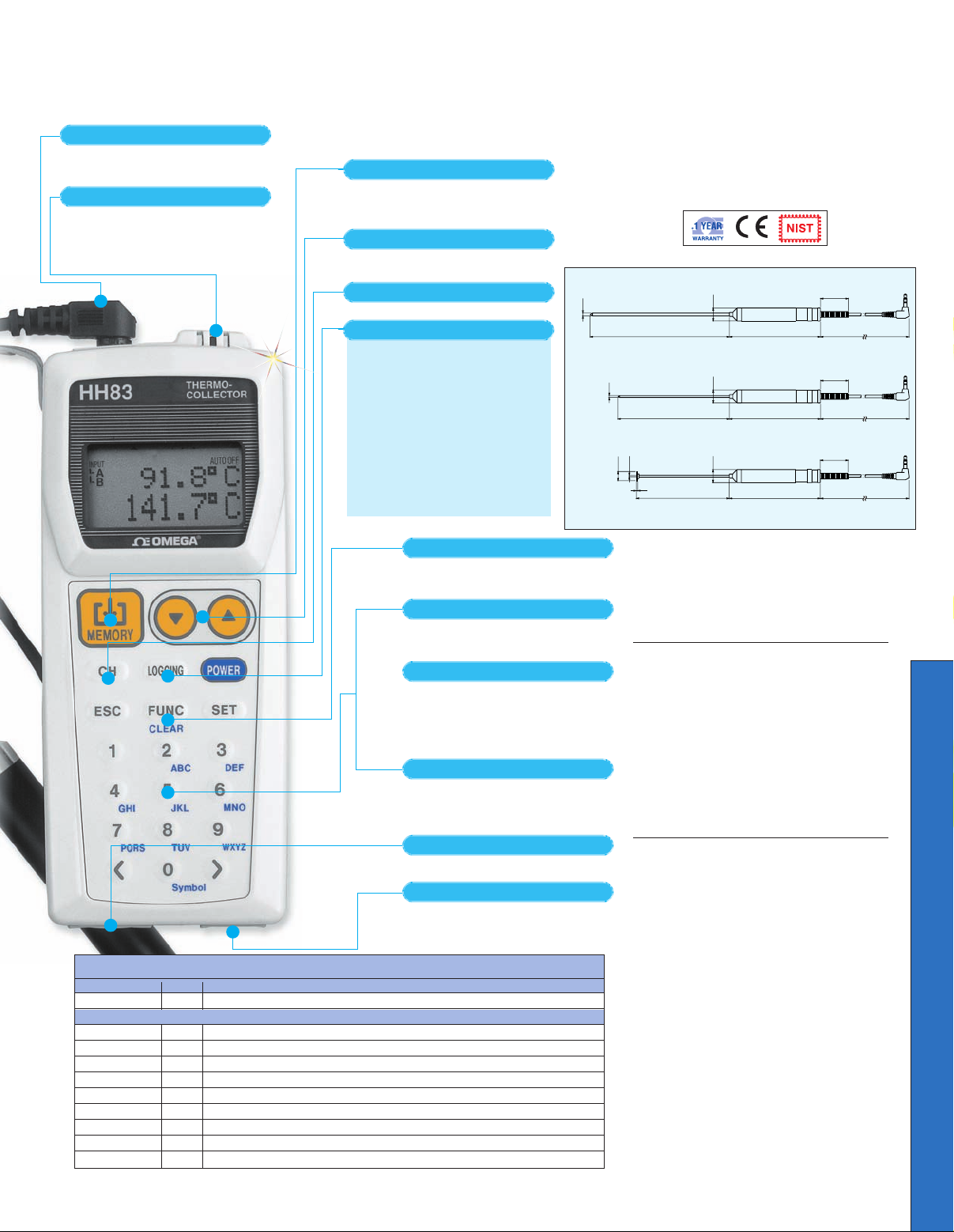
There are 4 types available: 2 needle probes for
mid-point temperature, a rounded end probe for liquid
temperature, and a surface probe for surface
temperature.
Measures ambient temperature, and allows for
continuous measurement inside a warehouse or
during transportation.
Each press of this key saves the measured data,
along with 3 other monitoring items: the name of
the object being measured, operator’s name,
and date and time of measurement.
Select from the list of up to 50 registered tag
names (objects to be measured).
With the (1) key, you can recall a list of up to
10 operator names and can also change any
of these names.
By pre-registering a list of up to 32 comments on
how to handle particular measurement failures,
you can keep records of how the measurement
failure was dealt with by selecting the desired
comment from the list using the (4) key.
(The HH83 supports this feature with HH83 Version 1.10
when used with application software version 1.30 or later.)
Register tag names, set alarm points, and define
measuring conditions, such as the measuring
interval for the logging mode. These setting
tasks can also be carried out from a PC.
Switches between the collector mode
(saves measured data when neces-
sary) and logging mode (saves
measured data continuously).
• When used in the collector mode
only, saves up to 5000 data items.*
• When used in the logging mode only,
saves up to 20000 data items.*
Measuring interval: 1 second to 24
hours (Under simultaneous 2-channel
measurement with the HH84,
2 seconds is the minimum.)
Start-of-measurement time:
timer can be set.
* Under simultaneous 2-channel measurement,
the HH84 saves 2 data items for one
measurement.
You can select setup items in the same way as
you choose options from the built-in menu of a
cellular phone.
For connecting to an optional non-contact probe.
Used to exchange data with a PC or send data
to a dedicated printer.
External probes (-30C to 200C) [-22F to 392F]
Memory key
Selection of registered tag name
Input selection key
User-friendly FUNC key
Selection of operator name
Record-keeping on measurement failure handling
Setup keys
Digital input terminal
RS232C I/O terminals
Collector/Logging mode selector key
Built-in sensor (-20C to 50C) [-4F to 122F]
HH83/84
Common Features
1.5 (0.06)
100 (3.9)
φ
φ
φ10 (0.4)
1.6 (0.06)
120 (4.7)
φ
φ2 (0.08)
150 (5.9)
98 (3.9)
98 (3.9)
98 (3.9)
30 (1.2)
30 (1.2)
30 (1.2)
600 (23.6)
600 (23.6)
600 (23.6)
φ14 (0.6)
14 (0.6)
14 (0.6)
φ3 (0.1)
HH83-NP/HH83-REP
HH83-HSNP
HH83-SP
Thermometer/Datalogger
Each press of this key saves the measured data,
along with 3 other monitoring items: the name of
the object being measured, operator’s name,
and date and time of measurement.
Select from the list of up to 50 registered tag
names (objects to be measured).
Switches between the collector mode
(saves measured data when necessary) and logging mode (saves
measured data continuously).
• When used in the collector mode
only, saves up to 5000 data items.*
• When used in the logging mode only,
saves up to 20000 data items.*
Measuring interval: 1 second to 24
hours (Under simultaneous 2-channel
measurement with the HH84,
2 seconds is the minimum.)
Start-of-measurement time:
timer can be set.
* Under simultaneous 2-channel measurement,
the HH84 saves 2 data items for one
measurement.
Memory key
Selection of registered tag name
Input selection key
Collector/Logging mode selector key
Thermistor Input
To Order (Specify Model Number)
Model No. Price Description
HH83 $580 Thermistor thermometer/datalogger with software and RS232 cable
Accessories
HH83-NP $126 Probe,150 x 3 mm diameter, needle tip
HH83-HSNP 182 Probe, 120 x 2 mm diameter, needle tip
HH83-REP 126 Probe, 150 x 3 mm diameter, round tip
HH83-SP 238 Probe, 100 x 1.6 mm diameter,10 mm diameter surface tip
WPC-80 25 Spare waterproof cover
SC-83 30 Soft carrying case
HH84-CABLE
HH-NIST 55 NIST-traceable calibration, no points
CAL-3-HH 75 NIST-traceable calibration with points
77 Spare RS232C cable
HH83,
$580,
shown
actual
size.
AVAILABLE FOR FAST DELIVERY!
L-44
HH83
$
580
Optional
Dimensions: mm (in)
Specifications
HH83-NP/HH83-REP
Measuring Range: -30 to 200°C
(-22 to 392°F)
Temperature Range and Accuracy:
Temp Range (T) Accuracy
-30°C ≤ T < -20°C ±1.0°C (Typical)
-20°C ≤ °C ≤ 0 ±0.5°C (Typical)
0°C ≤ °C < 100 ±0.5°C
100°C ≤ °C < 150 ±1.0°C (Typical)
150°C ≤ °C < 200 ±2.0°C (Typical)
Response: Approx 6 seconds for 90%
of final value
HH83-HSNP/HH83-SP
Measuring range: -30 to 200°C
(-22 to 392°F)
Temperature Range and Accuracy:
Temp Range (T) Accuracy
-30°C ≤ T < -20°C ±2.0°C (Typical)
-20°C ≤ °C ≤ 0 ±1.5°C (Typical)
0°C ≤ °C < 100 ±1.5°C (Typical)
100°C ≤ °C < 150 ±1.5°C (Typical)
150°C ≤ °C < 200 ±2.5°C (Typical)
Response:
HH83-HSNP: Approximately
2 seconds for 90% of final value
HH83-SP: Approximately 6 seconds
for 90% of value
Note: The accuracy ratings above were
obtained with the measurement of liquids
being agitated.
Probes are 316 SS with a 98 mm handle and
600 mm cable.
Comes with software, RS232C cable, 2 “AA”
batteries, waterproof cover, operator’s manual.
Ordering Example: HH83, thermistor
thermometer with HH83-SP, surface probe,
$580 + 238 = $818.
L
Page 2
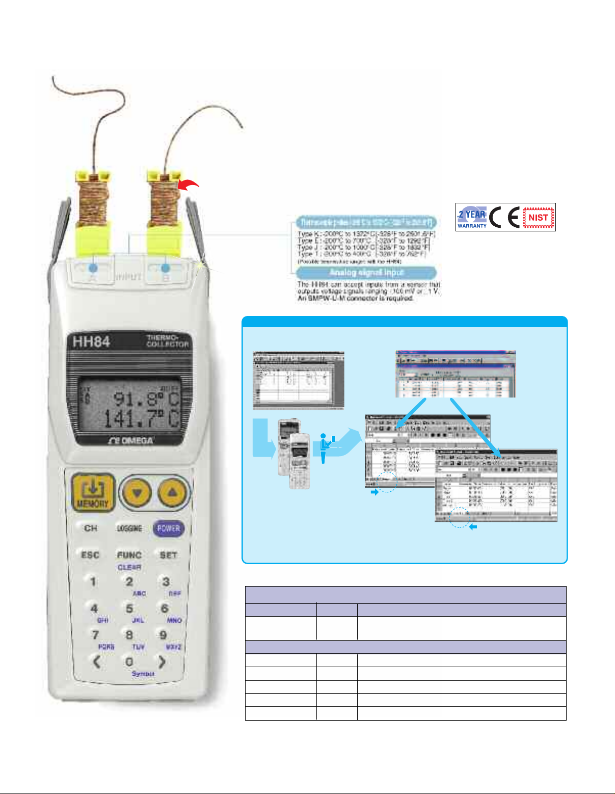
Thermometer/Datalogger
Easy data management using a PC (data management software included)
Setting measurement conditions from the PC.
(1)
Download the measurement conditions to the HH83/84.
(3) Upload the measured data to the PC.
(2)
Carry out measurement.
Tag name
Date of measurement
●Microsoft Excel spreadsheets are automatically generated for each object being measured (tag name)
and each date of measurement. Data collected later can also be added to these spreadsheets.
The HH83 supports this feature with HH83 Version 1.10 when used with application software version 1.30 or later.
Universal Dual
Thermocouple Input
$
2 Thermocouples
Included Free!
HH84
580
Optional
*
To Order (Specify Model Number)
Model No. Price Description
HH84 $580 Thermocouple thermometer/datalogger
HH84, $580, shown actual size.
Accessories
CAL-3-HH $75 NIST-traceable calibration, with points
HH-NIST
WPC-80 25 Spare waterproof cover
SC-800 10 Soft carrying case with belt loop
HH84-CABLE
Comes with 2 Type K beaded wire thermocouples, 2 “AA” batteries, software,
RS232C cable, waterproof cover and operator’s manual.
Ordering Example: HH84 thermometer/datalogger, $580.
*
L-45
AVAILABLE FOR FAST DELIVERY!
with software and RS232 cable
55 NIST-traceable calibration no points
77 Spare RS232C cable
Page 3

EMC standards EMI (interference signal): EN55011;1998, EN61326-1;1998+A1 (Class B, Group 1)
EMS (immunity): EN50082-1;1997, EN61326;1998+A1
Compliance with standards
HH83 Thermo-collector
Thermistor model
External thermistor -30C to 200C [-22F to 392F]
Built-in thermistor -20C to 50C [-4F to 122F]
Thermal emission (external probe) -20C to 400C [-4F to 752F]
Software, two AA-size alkaline dry batteries (LR6), a waterproof cover, an instruction manual, and Type K beaded wire T/C
HH84 Thermo-collector
Thermocouple model
Thermocouple Ty pe K : -200C to 1372C [-328F to 2501.6F]
Ty pe J : -200C to 1000C [-328F to 1832F]
Ty pe E : -200C to 700C [-328F to 1292F]
Ty pe T : -200C to 400C [-328F to 752F]
Thermal emission -20C to 400C [-4F to 752F]
Voltage input 100 mV, 1 V
1
(Selectable from 3 channels)
One channel is provided for each of the external thermistor probe, built-in thermistor sensor, and external non-contact probe.
2
(when A and B channels are used for thermocouple or voltage input)
1 (when D channel is used with the non-contact probe)
External thermistor: 0.1C
Built-in thermistor: 0.1C
External thermistor B u i l t - i n t h e rmistor
Te mperature range (T) Accuracy Temperature range (T) Accuracy
-30C T < -20C 1.0C -20C T 0C 1.0C
-20C T 0C 0.4C 0C T < 40C 0.8C
0C < T < 100C 0.3C 40C T 50C 1.0C
100C T < 150C 0.4C
150C T 200C 0.7C
Collector mode or Logging mode
Collector mode: 1 second or longer
Logging mode: 1 second to 24 hours
Maximum, minimum, and average Maximum, minimum, and average
Reading of difference between the 2 channels is possible.
None
5000 data items when used in collector mode only.
20000 data items when used in logging mode only.
Measurement data obtained in collector mode and logging mode
can coexist.
Conforms to IP54 standards (dust-proof and drip-proof requirements of IEC529)
LCD with backlight
-20C to 50C, 20 to 80% RH (no condensation)
Two AA-size alkaline dry batteries (LR6) (included)
Conforms to EIA RS-232C standard.
None
A maximum of 10, each comprising up to 8 alphanumeric characters
A maximum of 32, each comprising up to 8 alphanumeric characters
Upper- and lower-limit alarms
CPU: i486DX or higher Recommended memory capacity: 16 MB or greater
OS: Windows 95/Windows 98/Windows NT 4.0 Serial I/O capability:
A serial port conforming to RS-232C standard should be available.
FDD: 3.5", 1.44 MB-formatted Software: Microsoft Excel 95, Microsoft Excel 97
Required space on the HDD: 10 MB or greater
Chime, function lock, clock display, auto power-off, and battery alarm
Approx. 3 months when operated in logging mode at 10-minute intervals;
Approx. 1 month when operated in logging mode at 1-minute intervals;
Approx. 2 weeks when operated in collector mode 8 hours a day.
Thermocouple: 0.1C
Voltage input: 0.1 mV or 0.001 V
Collector mode: 0.5 seconds or longer when 1 channel is used.
1 second or longer when 2 channels are used.
Logging mode: 1 second to 24 hours when 1 channel is used.
2 seconds to 24 hours when 2 channels are used.
Scales the voltage input x according to the formula “Ax + B,” which
is defined from the thermo-collector software.
5000 data items when used in collector mode only.
20000 data items when used in logging mode only.
M
easurement data obtained in collector mode and logging mode
can coexist .
Under simultaneous 2-channel measurement, 2 data items are
recorded at the same time.
0C to 50C, 20 to 80% RH (no condensation)
Corrects the measured data from thermocouple input within the range of 20.0C.
Approx. 1.5 months when operated in logging mode at 10-minute intervals;
Approx. 1 month when operated in logging mode at 1-minute intervals;
Approx. 5 days when operated in collector mode 8 hours a day including 30
minutes of communication.
A maximum of 50, each comprising up to 8 alphanumeric characters
Approx. 133(H) × 56(W) × 33(D) mm
(excluding protrusions)
Weight: Approx. 170 g
(including batteries)
Approx. 151(H) × 56(W) × 33(D) mm
(excluding protrusions)
Weight: Approx. 180 g
(including batteries)
T
hermocouple -100C T: (0.1% of rdg + 0.3C)
T < -100C: (0.1% of rdg + 0.6C)
Reference junction compensation is 0.4C when the temperature of
the input terminal is in equilibrium
Thermal emission(1% of rdg + 1C) or 3C, depending on the
accuracy of the non-contact probe.
Voltage input (0.1% of rdg + 0.2% of range)
33
29
133
56
* For the accuracy when using a non-
contact probe (900 03), see the
P
roduct name
(Model)
N
umber of measuring
channels
Measuring range
(
only the main unit)
Supplied accessories
R
esolution
Accuracy
(only the main unit)
Measuring mode
Measuring interval
Computing function
Scaling function
Data capacity
Drip-proof construction
Display
Operating temperature and humidity
Power requirements
Communication function
Simplified correction function
Registration of operator names
Registration of comments
Alarm function
Thermo-collector software
system requirements
External dimensions
Other functions
Battery life
Registration of tag names
29
33
56
151
HH83
THERMOCOLLECTOR
®
HH84
THERMOCOLLECTOR
®
Thermometer/Datalogger
Thermocouple Input Specifications
L-46
L
Page 4

One Omega Drive | Stamford, CT 06907 | 1-888-TC-OMEGA (1-888-826-6342) | info@omega.com
EPG05
www.omega.com
UNITED KINGDOM
www. omega.co.uk
Manchester, England
0800-488-488
UNITED STATES
www.omega.com
1-800-TC-OMEGA
Stamford, CT.
CANADA
www.omega.ca
Laval(Quebec)
1-800-TC-OMEGA
GERMANY
www.omega.de
Deckenpfronn, Germany
0800-8266342
Karviná, Czech Republic
FRANCE
www.omega.fr
Guyancourt, France
088-466-342
CZECH REPUBLIC
www.omegaeng.cz
596-311-899
BENELUX
www.omega.nl
Amstelveen, NL
0800-099-33-44
More than 100,000 Products Available!
Temperature
Calibrators, Connectors, General Test and Measurement
Instruments, Glass Bulb Thermometers, Handheld Instruments
for Temperature Measurement, Ice Point References,
Indicating Labels, Crayons, Cements and Lacquers, Infrared
Temperature Measurement Instruments, Recorders Relative
Humidity Measurement Instruments, RTD Probes, Elements
and Assemblies, Temperature & Process Meters, Timers and
Counters, Temperature and Process Controllers and Power
Switching Devices, Thermistor Elements, Probes and
Assemblies,Thermocouples Thermowells and Head and Well
Assemblies, Transmitters, Wire
Flow and Level
Air Velocity Indicators, Doppler Flowmeters, Level
Measurement, Magnetic Flowmeters, Mass Flowmeters,
Pitot Tubes, Pumps, Rotameters, Turbine and Paddle Wheel
Flowmeters, Ultrasonic Flowmeters, Valves, Variable Area
Flowmeters, Vortex Shedding Flowmeters
pH and Conductivity
Conductivity Instrumentation, Dissolved Oxygen
Instrumentation, Environmental Instrumentation, pH
Electrodes and Instruments, Water and Soil Analysis
Instrumentation
Data Acquisition
Auto-Dialers and Alarm Monitoring Systems,
Communication Products and Converters, Data
Acquisition and Analysis Software, Data Loggers
Plug-in Cards, Signal Conditioners, USB, RS232, RS485
and Parallel Port Data Acquisition Systems, Wireless
Transmitters and Receivers
Pressure, Strain and Force
Displacement Transducers, Dynamic Measurement
Force Sensors, Instrumentation for Pressure and Strain
Measurements, Load Cells, Pressure Gauges, Pressure
Reference Section, Pressure Switches, Pressure Transducers,
Proximity Transducers, Regulators,
Strain Gages, Torque Transducers, Valves
Heaters
Band Heaters, Cartridge Heaters, Circulation Heaters,
Comfort Heaters, Controllers, Meters and Switching
Devices, Flexible Heaters, General Test and Measurement
Instruments, Heater Hook-up Wire, Heating Cable
Systems, Immersion Heaters, Process Air and Duct,
Heaters, Radiant Heaters, Strip Heaters, Tubular Heaters
click here to go to the omega.com home page
 Loading...