

Page 1
User’s Guide
Shop online at
omega.com
e-mail: info@omega.com
For latest product manuals:
omegamanual.info
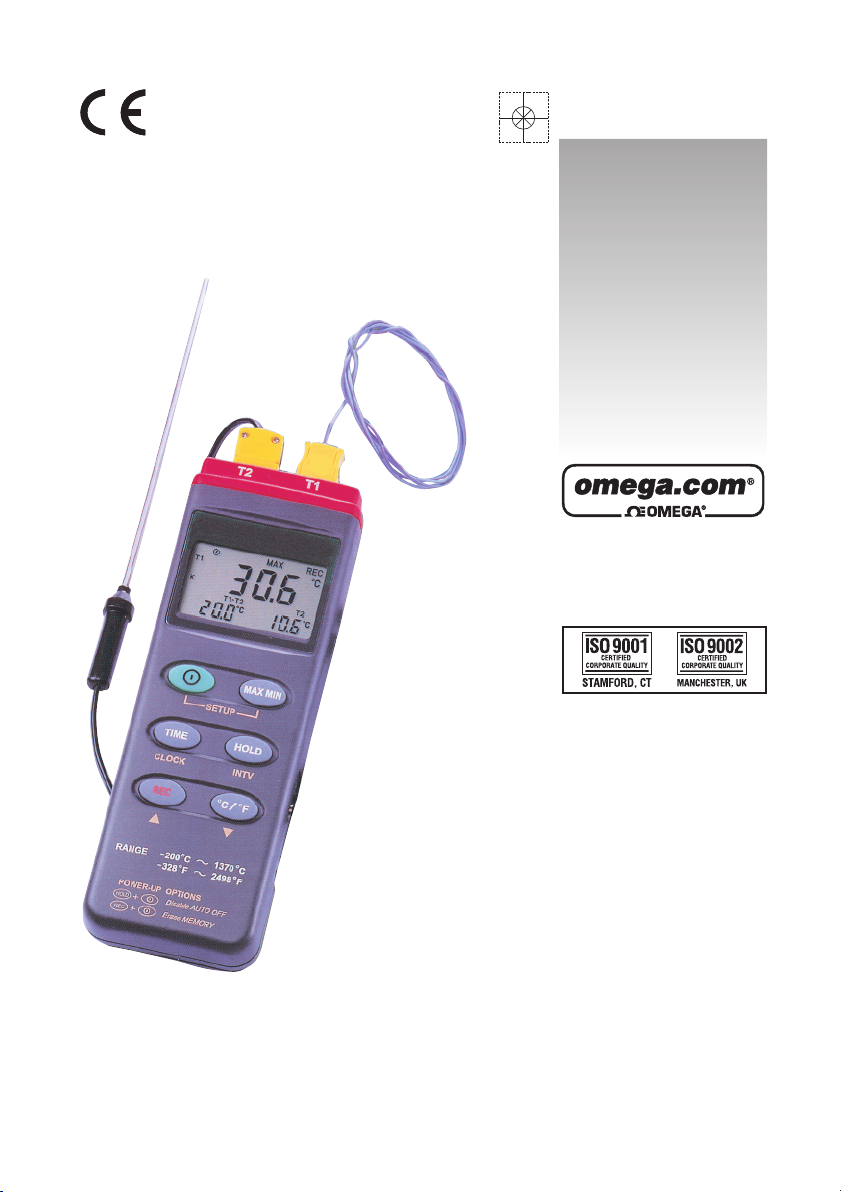
OMEGAETTE
®
HH306A
Thermometer/Data Logger
Page 2

OMEGAnet®Online Service Internet e-mail
omega.com info@omega.com
Servicing North America:
U.S.A.: One Omega Drive, Box 4047
ISO 9001 Certified Stamford, CT 06907-0047
Tel: (203) 359-1660
FAX: (203) 359-7700
e-mail: info@omega.com
Canada: 976 Bergar
Laval (Quebec) H7L 5A1, Canad
Tel: (514) 856-6928
FAX: (514) 856-6886
e-mail: info@omega.c
a
a
For immediate technical or application assistance:
U.S.A. and Canada: Sales Service: 1-800-826-6342/1-800-TC-OMEGA
Customer Service: 1-800-622-2378/1-800-622-BEST
Engineering Service: 1-800-872-9436/1-800-USA-WHEN
Mexico: En Espan˜ol: (001) 203-359-7803
FAX: ( 001) 203-359-7807
e-mail: espanol@omega.com
info@omega.com.m
x
®
Servicing Europe:
Czech Republic: Frystatska 184, 733 01 Karviná, Czech Republic
Germany/Austria: Daimlerstrasse 26, D-75392 Deckenpfronn, Germany
United Kingdom: One Omega Drive, River Bend Technology Centre
ISO 9002 Certified Northbank, Irlam, Manchester
Tel: +420 (0)59 6311899
FAX: +420 (0)59 6311114
Toll Free: 0800-1-66342
e-mail: info@omegashop.cz
Tel: +49 (0)7056 9398FAX: +49 (0)7056 9398-29
Toll Free in Germany: 0800 639 7678
e-mail: info@omega.d
M44 5BD United Kingdo
Tel: +44 (0)161 777 6611
FAX: +44 (0)161 777 6622
Toll Free in United Kingdom: 0800-488-488
e-mail: sales@omega.co.uk
0
e
m
®
®
It is the policy of OMEGA Engineering, Inc. to comply with all worldwide safety and EMC/EMI
regulations that apply. OMEGA is constantly pursuing certification of its products to the European New
Approach Directives. OMEGA will add the CE mark to every appropriate device upon certification.
The information contained in this document is believed to be correct, but OMEGA accepts no liability for any
errors it contains, and reserves the right to alter specifications without notice.
WARNING: These products are not designed for use in, and should not be used for, human applications.
Page 3

CONTENTS
TITLE PAGE
I. Introduction
II. Specifications
III. Symbol Definition and Button Location
IV. Operation Instructions
4.1 Power-Up………………………………………………………………………………….... 3
4.2 Connection the Thermocouples………………………………………………………...
4.3 Selecting the Temperature Scale……………………………………………………….
4.4 Data-Hold Operation………………………………………………………………………
4.5 DataLogger…………………………………………………………………………………
4.6 Clock Setup ………………………………………………………………………………..
4.7 Recording Interval Setup……..………………………………………………………….
4.8 Time Operation…………………………………………………………………………….
4.9 MAX/MIN Operation……………………………………………………………………….
4.10 Auto Power Off……………………………………………………………………………
4.11 Low Battery Condition ………………………………………………………………….
4.12 Calibration Point…………………………………………………………………………
4.13 Digital Output……………………………………………………………………………..
V. Setup SE-305 (Thermo DataLogger)—RS232 interface
software
…………………………………………………………………………….….. 1
…………………………………………………………………………… 1
………………………………. 2
…………………………………………….……………… 3
3
3
3
3
4
4
4
4
4
5
……………………………………………………………………………………… 7
3
4
Page 4
HH306A
I. Introduction:
This instrument is a digital thermometer for use with any K-type thermocouple as temperature
sensor. Temperature indication follows National Bureau of Standards and IEC584
temperature/voltage table for K-type thermocouples. Its internal memory can keep up to 16312
records.(note1.) It uses RS232 interface to perform bi-directional communication with PC.
II. Specifications:
Numerical Display: 4 digital Liquid Crystal Display
Measurement Range: -200°C ~ 1370°C ; -328°F ~ 2498°F
Resolution: -200°C~ 200°C 0.1°C; 200°C ~1370°C 1°C
Input Protection at Thermocouple Input: 60V DC, or 24Vrms AC
Environmental:
R Operating Temperature and Humidity: 0°C ~50°C (32°F ~ 122°F); 0 ~ 80% RH
R Storage Temperature and Humidity: -10°C to 60°C (14°F ~ 140°F); 0 ~ 80% RH
R Altitude up to 2000 meters.
Accuracy: at ( 23 ± 5°C )
-200°C ~ 200°C ±(0.2% reading + 1°C)
200°C ~ 400°C ±(0.5% reading + 1°C)
400°C~1370°C ±(0.2% reading + 1°C)
-328°F ~ -200°F ±(0.5% reading + 2°F)
-200°F ~ 200°F ±(0.2% reading + 2°F)
200°F ~ 2498°F ±(0.3% reading + 2°F)
The basic accuracy Specification does not include the error of the probe. Please refer to the
probe accuracy specification for additional details.
Sample Rate: 1.25 times per second
Dimension: 184×64×30mm
Weight: 210g Approx.
Accessory: K Type Bead Probe, Battery, Carrying Case, Instruction Menu, Software program,
Power requirement: 9 Volt Battery
Battery Life: Approx. 100hrs with alkaline battery
AC Adapter: 9VDC ±15% 100mA
Plug Diameter: 3.5mm×1.35mm
Option : AC Adapter
-200°F~ 200°F 0.1°F; else 1°F
Range Accuracy
Temperature Coefficient:
For ambient temperatures from 0°C ~ 18°C and 28°C
~ 50°C, for each °C ambient below 18°C or above
28°C add the following tolerance into the accuracy
spec.
Note:
RS-232 & USB Connection Cable.
0.01% of reading + 0.03°C
( 0.01% of reading + 0.06°F )
note1:
Every time you press "REC" button to start recording data and press "REC" button again to stop
recording, there will be a data set in memory, you can store as many data sets as you want until memory
is full.
1
Page 5
HH306A
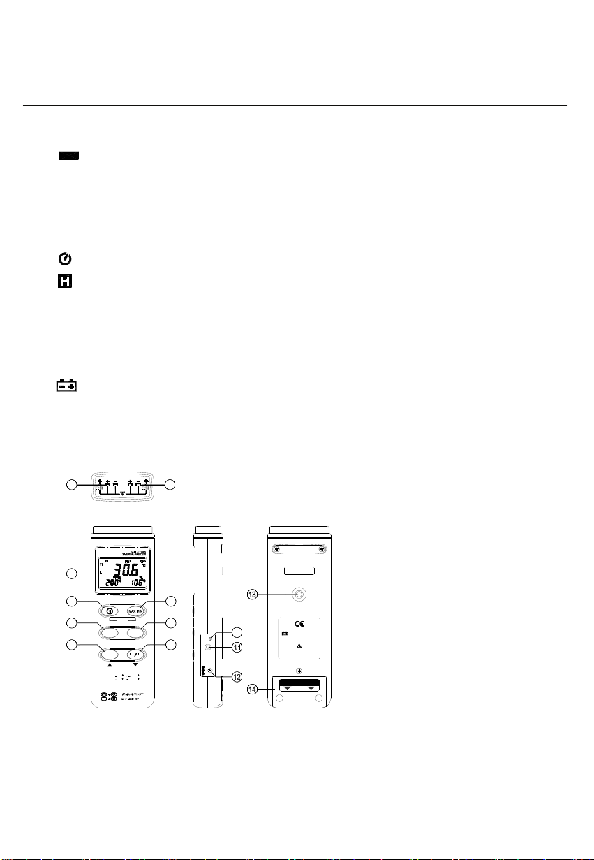
III. Symbol Definition and Button Location:
: This indicates that the minus temperature is sensed.
°C°F
: Centigrade and Fahrenheit indication.
K
: Thermocouple Type Indication
MAX
: The Maximum value is now being displayed
MIN
: The Minimum value is now being displayed
: This indicates auto power off is enabled.
: This indicates that the display data is being held.
m-d
: it indicates the value below is month and day
h:m
: it indicates the value below is hour and minute
m:s
: it indicates the value below is minute and second
y
: it indicates year is displayed in the main window.
: The Battery is not sufficient for proper operation.
REC
: This indicates that the tester is recording. If it blinks, it indicates the memory is full.
2
2
3
4
5
6
SETUP
TIME
CLOCK
REC
200
RANGE:
328
POWER-UP OPTIONS
REC
C
F 2498
1
T1T
T1T2
7
8
HOLD
INTV
9
F
C
1370
C
F
10
L
A
C
T
U
P
T
U
O
V
9
C
D
9V BATTERY
NEDA 1604 6F22 006P
PLEASE READ
MANUAL FOR SAFETY
OPEN
2
Button Location:
1
K type temperature sensor T1 input
○
connector
2
K type temperature sensor T2 input
○
connector
3
○
LCD display
4
ON/OFF button
○
5
Time display button
○
6
Record button
○
7
MAX MIN function control button
○
8
HOLD button
○
9
°C, °F control button
○
10
Offset calibration screw
○
11
Digital output connector
○
12
AC power adapter connector
○
13
Tripod connector
○
14
○
Battery cabinet cover
Page 6

HH306A
IV. Operation Instructions:
4.1 Power-Up
Press the
When the user powers on, the LCD will show how much memory
space is available to use.
For example: It indicates that there are 16,000 records memory space available.
4.2 Connection the Thermocouples
For measurement, plug the thermocouple into the input connectors.
4.3 Selecting the Temperature Scale
When the meter is first powered on, the default scale setting is set at Celsius (°C) scale. The user
may change it to Fahrenheit (°F) by pressing “ °C/°F ” button and vice versa to Celsius. Next time
you power on, the scale setting will be the same as which when you powerd off last time.
4.4 Data-Hold Operation
The user may hold the present reading and keep it on the display by pressing the “HOLD” button.
When the held data is no longer needed, one may release the data-hold operation by pressing
“HOLD” button again.
When the meter is under Data Hold operation, the “TIME”, "MAX MIN" and “ °C/°F ” button are
disabled. (when you press "TIME” ,“ °C/°F ” and "max min" button in HOLD mode, there will be
two continuous beeps)
To exit the MAX/MIN mode, one may press and hold "MAX MIN" button for two seconds.
4.5 DataLogger:
When one presses the "REC" button, the meter will start recording,
and pressing the "REC" button again will stop recording, If you
want to clear the memory, power off the meter, then press and hold
“REC” button and then press power button and hold at least 2
seconds, then release all buttons ,then LCD will show "CLR" to
clear the memory.
4.6 Clock Setup:
power button
to turn the thermometer ON or OFF.
1: press and hold “MAX MIN” button and then power on the meter:
2: press “TIME”(clock):
3: press "REC" ▲ or "°C/°F" ▼ to increase or decrease number,
press “TIME”(clock) to adjust next item. The adjusting order is
year→month→ day→hour→ minute, then press “TIME” (clock) to
finish adjusting. If you want abort during a setup process, press
power button to cancel.
3
Page 7

HH306A
4.7 Recording Interval Setup :
1: press and hold “MAX MIN” button and then power on the meter:
2: press “HOLD"(INTV)
3: press "REC" ▲ or "°C/°F" ▼ to increase or decrease number,
press “HOLD" (INTV) to adjust next item, then press “HOLD” (INTV)
to finish. If you want abort during a setup process, press power
4.8 Time Operation:
When pressing the “TIME” button, the LCD will display time , it will show year on top of the LCD,
show month and day on the left bottom of the LCD, show hour and minute on the right bottom of
the LCD. Press "TIME" button or any other button will exit this mode. This operation will not interrupt
the recording and "MAX MIN" operation.
4.9 MAX/MIN Operation:
When pressing the "MAX MIN" button the meter will enter the MAX/MIN mode. Under this mode the
maximum value, minimum value is kept in the memory simultaneously and updated with every new
sample of data.
When the MAX symbol is display, the Maximum is shown on the display.
Press "MAX MIN" again, then the MIN symbol is on the display and also the minimum reading.
Press "MAX MIN" again, MAX, and MIN will blink together. This means that all these data is updated
in the memory and the reading is the present temperature.
One may press "MAX MIN" to circulate the display mode among these options.
When the meter is under "MAX MIN" operation and “ °C/°F ” button are disabled.(when you press
“ °C/°F ” button in "MAX MIN" mode, there will be two continuous beep)
To exit the MAX/MIN mode, one may press and hold "MAX MIN" for two seconds.
4.10 Auto Power Off:
By default, when the meter is powered on, it is under auto power off mode. The meter will power
itself off after 30 minutes if no key operation and no RS232 communication combination at power on
can disable auto power off.
One may press and hold “HOLD” button and then power on the meter and there will be two
successive beeps to indicate that auto power off is disabled and the will not show up.
4.11 Low Battery Condition
When the battery voltage is under proper operation requirement, the symbol will show on the
LCD and the battery need to be replaced with new one.
4.12 Calibration Point:
input Adjust VR tolerance
0 °C VR1 ± 0.1 °C
190 °C VR2 ± 0.1 °C
1000 °C VR3 ± 1 °C
1900 °F VR4 ± 1 °F
button to cancel.
P. S
Normally, performing offset Calibration with thermal
stabled ice water through VR1 will give a very good
calibration result.
4
Page 8

HH306A
4.13 Digital Output:
The Digital Output is a 9600bps N 81 serial interface.
The RX is a 5V normal high input port.
The TX is a 5V normal high output port.
The command of Digital Output is list below:
RS232 command Function Remarks
K(ASC 4BH) Ask for model No. Return 4 bytes
A(ASC 41H) Inquire all encoded data Return encoded 10 byte
H(ASC 48H) Hold button
M(ASC 4DH) MAX/MIN button
N(ASC 4EH) Exit MAX/MIN mode
T(ASC 52H) TIME button
C(ASC 43H) C/F button
U(ASC 55H) Dump all memory of thermometer return 32768 bytes
P(ASC 50H) Load recorded data
‧Command K:
Return 4 bytes. For example, when sending command "K" to the meter, it will return "3","0","6",
ASCII(13) .
‧Command U:
Return 32768 bytes.
‧Command P:
Instead of returning all 32768 bytes, it only return recorded data.
‧Command H:
Equivalent to one pushing on the HOLD button and no message is returned.
‧Command M:
Equivalent to one pushing on the MAX/MIN button and no message is returned.
‧Command N:
Equivalent to one pushing and hold the MAX/MIN button for two seconds to exit MAX/MIN mode.
‧Command T:
Equivalent to one pushing on the TIME button and no message is returned.
‧Command C:
Equivalent to one pushing on the °C/°F button and no message is returned.
‧Command A:
nd
1
BYTE:
The first byte is the start byte , it value is 2.
nd
2
BYTE:
bit7 bit6 bit5 bit4 bit3 bit2 bit1 bit0
C/F Low Bat Hold TIME MAX/MIN REC
bit 0: 1→recording mode, 0→not recording
bit 2 bit 1
0 0 →normal mode
0 1 →MAXIMUM mode
1 0 →MINIMUM mode
1 1 →calculate MAX/MIN in background mode .
5
TX
RX
GND
Page 9

HH306A
bit3: 1→Indicates the LCD is displaying time.
bit4: no use
bit5: 1→HOLD, 0→not HOLD
bit6: 1→LOW BATTERY , 0→BATTERY NORMAL
bit7: 1→°C 0→°F
th
BYTE:
3
bit7 bit6 bit5 bit4 bit3 bit2 bit1 bit0
Auto Power Off memory full resolution sign OL resolution sign OL
bit0: 1→T1 is OL, 0→not OL
bit1: 1→T1 value is minus, 0→T1 value is plus.
bit2: 1→4
bit3: 1→T2 is OL, 0→not OL
bit4: 1→T2 value is minus, 0→T2 value is plus.
bit5: 1→8
bit6: 1→Memory is full. 0→Memory is not full.
bit7: 1→Auto power off enabled. 0→Auto power off disabled.
th
4
th
5
th
6
If bit3 of 2
If bit3 of 2
th
7
If bit3 of 2
If bit3 of 2
th
8
If bit3 of 2
If bit3 of 2
th
9
If bit3 of 2
If bit3 of 2
10
th
byte and 5th byte represent #### , 0→4th byte and 5th byte represent ###.#
th
byte and 9th byte represent #### , 0→8th byte and 9th byte represent ###.#
BYTE: first two BCD code of T1 value.
BYTE:last two BCD code of T1 value
BYTE:
nd
BYTE =0 : first two BCD code of T1-T2 value.
nd
BYTE =1 : two BCD code of month.
BYTE:
nd
BYTE =0 : last two BCD code of T1-T2 value.
nd
BYTE =1 : two BCD code of day.
BYTE:
nd
BYTE =0 : first two BCD code of T2 value.
nd
BYTE =1 : two BCD code of hour.
BYTE:
nd
BYTE =0 : last two BCD code of T2 value.
nd
th
BYTE =1 : two BCD code of minute.
BYTE: end byte, it value is 3, 1
nd
and 10th are used to check frame error.
Appendix: Thermo couple probe specification
Model Range Tolerances Description
TP-K01
Bead probe
TP-K01:
-50℃ to 200℃
-58℉ to 392℉
±2.2℃ or ±0.75%
(±3.6℉ or ±0.75%)
with Teflon tape insulation Maximum
insulating temperature : 260℃
probe for general condition measurements, especially for
complex and hard to reach places.
6
Page 10

HH306A
—
V. Setup SE-305 (Thermo DataLogger)
y The SE-305 package contains:
1.One setup CD.
2.Custom designed RS232 cable for SE-305.
y System Required:
Windows 98/ NT 4.0/ NT2000/ XP/ VISTA.
y Minimum Hardware Required:
486-100 MHz PC compatible, 16 MB RAM;
At least 5 MB hard disk space available to install SE-305 program. Recommended display
resolution is 800X600.
y Install SE-305:
1.We recommend close all other application before installing SE-305.
2.Insert the SE-305 CD-ROM into your CD drive. The SE-305 installer should start automatically.
If it does not, you can start it by running SETUP.EXE from the root drive of the CD-ROM.
3.When installation is complete, it will copy SE305.exe(executable file) and help file to your hard
disk(default is c:\program files\ SE305)
4.For other operation instruction, please refer to the on-line help while executing SE-305.
RS232 interface software:
Main Menu
Main Menu
Panel simulator
File | Open- Retrieve files from the disk.
Save - Save the active window (when the caption bar is highlighted) data to the disk.
Print - Print the data of the active window (graph or list).
Printer Setup - Select printer.
File | Exit: Terminates SE305 program.
7
Graph
Tabular
Page 11

HH306A
View | Control Panel:
By opening the Panel Window, the user can control meter via the button in this window.
View | Real-Time Graph:
Open Real-Time Graph display to graph the present data.
Real Time | Run - Start collecting real time data.
Stop - Stop collecting real time data.
DataLogger:
By opening the DataLogger Window, the user can load recorded data of meter to PC in this
window.
ComPort: Select the port manually.
Option: | Range : Change the Y axis extension.
Graph Customization : Graph Customization.
For more operation instruction, please refer to the online help while executing
SE-305.
8
Page 12

NOTES:
HH309A
7
Page 13

NOTES:
HH309A
7
Page 14

NOTES:
HH309A
7
Page 15

WARRANTY/ DISCLAIMER
OMEG A ENGINEERI NG , IN C. w ar rants this uni t to be free o f defects in mater ials a nd
workmanship for a period of 13 months from date of purchase. OMEGA’s WARRANTY adds an
additional one (1) month grace period to the normal one (1) year product warranty to cover
handlin g and shipping ti me. This ensu re s that OMEGA’ s customers receiv e maximum
coverage on each product.
If the unit malfunctions, it must be returned to the factory for evaluation. OMEGA’s Customer
Service Department will issue an Authorized Return (AR) number immediately upon phone or
written request. Upon examination by OMEGA, if the unit is found to be defective, it will be
repaired or replaced at no charge. OMEGA’s WARRANTY does not apply to defects resulting
from any action of the purchaser, including but not limited to mishandling, improper interfacing,
operatio n outs ide of design limits, im prope r repa ir, or unauthorized modification. This
WARRANTY is VOID if the unit shows evidence of having been tampered with or shows evidence
of having been damaged as a result of excessive corrosion; or current, heat, moisture or vibration; improper specification; misapplication; misuse or other operating conditions outside of
OMEGA’s control. Components in which wear is not warranted, include but are not limited to
contact points, fuses, and triacs.
OMEGA is pleased to offer suggestions on the use of its various products. However,
OMEGA neither assumes responsibility for any omissions or errors nor assumes liability
for any damages that result from the use of its products in accordance with information
provided by OMEGA, either verbal or written. OMEGA warrants only that the parts
manufactured by the company will be as specified and free of defects. OMEGA MAKES
NO OTHER WARRANTIES OR REPRESENTATIONS OF ANY KIND WHATSOEVER,
EXPRESSED OR IMPLIED, EXCEPT THAT OF TITLE, AND ALL IMPLIED WARRANTIES
INCLUDING ANY WARRANTY OF MERCHANTABILITY AND FITNESS FOR A PARTICULAR
PURPOSE ARE HEREBY DISCLAIMED. LIMITATION OF LIABILITY: The remedies of purchaser set forth herein are exclusive, and the total liability of OMEGA with respect to this
order, whether based on contract, warranty, negligence, indemnification, strict liability or
otherwise, shall not exceed the purchase price of the component upon which liability is
based. In no event shall OMEGA be liable for consequential, incidental or special damages.
CONDITIONS: Equipment sold by OMEGA is not intended to be used, nor shall it be used: (1) as
a “Basic Component” under 10 CFR 21 (NRC), used in or with any nuclear installation or activity;
or (2) in medical applications or used on humans. Should any Product(s) be used in or with any
nuclear installation or activity, medical application, used on humans, or misused in any way,
OMEGA assumes no responsibility as set forth in our basic WARRANTY/ DISCLAIMER language,
and, additionally, purchaser will indemnify OMEGA and hold OMEGA harmless from any liability
or damage whatsoever arising out of the use of the Product(s) in such a manner.
Direct all warranty and repair requests/inquiries to the OMEGA Customer Service Department.
RETURN REQUESTS/INQUIRIES
BEFO RE RET UR NING ANY PRODU CT(S) TO OMEGA, PURCHAS ER MUS T OB TAIN AN
AUTHORIZED RETURN (AR) NUMBER FROM OMEGA’S CUSTOMER SERVICE DEPARTMENT
(IN ORDER TO AVOID PROCESSING DELAYS). The assigned AR number should then be
marked on the outside of the return package and on any correspondence.
The purchaser is responsible for shipping charges, freight, insurance and proper packaging to
prevent breakage in transit.
FOR WARRANT
the following information available BEFORE
contacting OMEGA:
1. Purchase Order number under which
the product was PURCHASED
2. Model and serial number of the produc
under warranty, and
3. Repair instructions and/or specific
problems relative to the product.
OME GA’s policy is to ma ke run ning changes , not model ch ang es, wh eneve r an impro vem ent is po ssibl e.
This affords our customers the latest in technology and engineering.
OMEGA is a registered trademark of OMEGA ENGINEERING, INC
© Copyright 2008 OMEGA ENGINEERING, INC. All rights reserved. This document may not be copied, photocopied,
reproduced, translated, or reduced to any electronic medium or machine-readable form, in whole or in part, without
the prior written consent of OMEGA ENGINEERING, INC
Y RETURNS, please have
,
FOR NON-WARRANTY REPAIRS,
OMEGA for current repair charges. Have the
following information available BEFORE
contacting OMEGA:
1. Purchase Order number to cover the COST
t
of the repair,
2. Model and serial number of the product, and
3. Repair instructions and/or specific problems
relative to the product.
.
.
consult
Page 16

Where Do I Find Everything I Need for
Process Measurement and Control?
OMEGA…Of Course!
Shop online at omega.com
TEMPERATURE
Thermocouple, RTD & Thermistor Probes, Connectors, Panels & Assemblies
Wire: Thermocouple, RTD & Thermisto
Calibrators & Ice Point References
Recorders, Controllers & Process Monitors
Infrared Pyrometers
PRESSURE, STRAIN AND FORCE
Transducers & Strain Gages
Load Cells & Pressure Gages
Displacement Transducers
Instrumentation & Accessories
FLOW/LEVEL
Rotameters, Gas Mass Flowmeters & Flow Computers
Air Velocity Indicators
Turbine/Paddlewheel Systems
Totalizers & Batch Controllers
pH/CONDUCTIVITY
pH Electrodes, Testers & Accessories
Benchtop/Laboratory Meters
Controllers, Calibrators, Simulators & Pumps
Industrial pH & Conductivity Equipment
r
SM
DATA ACQUISITION
Data Acquisition & Engineering Softwar
Communications-Based Acquisition Systems
Plug-in Cards for Apple, IBM & Compatibles
Datalogging Systems
Recorders, Printers & Plotters
e
HEATERS
Heating Cable
Cartridge & Strip Heaters
Immersion & Band Heaters
Flexible Heaters
Laboratory Heaters
ENVIRONMENTAL
MONITORING AND CONTRO
Metering & Control Instrumentation
Refractometers
Pumps & Tubing
Air, Soil & Water Monitor
Industrial Water & Wastewater Treatment
pH, Conductivity & Dissolved Oxygen Instruments
s
L
M3546A/0508
 Loading...