

Page 1
omega.com
e-mail: info@omega.com
For latest product manuals:
omegamanual.info
SOFTWARE FOR HH147U
Handheld Thermometer
K/J/T/E/R/S/N Types
Windows 98/Windows 2000/
Windows XP
(Windows 2000/Windows XP
are recommended)
HH147U
Software for Data Logger Thermometer
Ver. V1.0.12
®
, ENGINEERING
INC .
omega.com
®
1-800-USA-WHEN (1-800-872-9436)
© COPYRIGHT 2009 OMEGA ENGINEERING, INC.
Shop online at
User’s Guide
Page 2

Servicing North America:
U.S.A.: Omega Engineering, Inc., One Omega Drive, P.O. Box 4047
ISO 9001 Certified
Stamford, CT 06907-0047
Toll-Free: 1-800-826-6342 Tel: (203) 359-1660
FAX: (203) 359-7700 e-mail: info@omega.com
Canada: 976 Bergar
Laval (Quebec), Canada H7L 5A1
Toll-Free: 1-800-826-6342 TEL: (514) 856-6928
FAX: (514) 856-6886 e-mail: info@omega.ca
For immediate technical or application assistance:
U.S.A. and Canada: Sales Service: 1-800-826-6342/1-800-TC-OMEGA
®
Customer Service: 1-800-622-2378/1-800-622-BEST
®
Engineering Service: 1-800-872-9436/1-800-USA-WHEN
®
Mexico: En Español: 001 (203) 359-7803 FAX: (001) 203-359-7807
info@omega.com.mx e-mail: espanol@omega.com
Servicing Europe:
Benelux: Managed by the United Kingdom Office
Toll-Free: 0800 099 3344 TEL: +31 20 347 21 21
FAX: +31 20 643 46 43 e-mail: sales@omega.nl
Czech Republic: Frystatska 184
733 01 Karviná, Czech Republic
Toll-Free: 0800-1-66342 TEL: +420-59-6311899
FAX: +420-59-6311114 e-mail: info@omegashop.cz
France: Managed by the United Kingdom Office
Toll-Free: 0800 466 342 TEL: +33 (0) 161 37 29 00
FAX: +33 (0) 130 57 54 27 e-mail: sales@omega.fr
Germany/Austria: Daimlerstrasse 26
D-75392 Deckenpfronn, Germany
Toll-Free: 0 800 6397678 TEL: +49 (0) 7059 9398-0
FAX: +49 (0) 7056 9398-29 e-mail: info@omega.de
United Kingdom: OMEGA Engineering Ltd.
ISO 9001 Certified
One Omega Drive, River Bend Technology Centre, Northbank
Irlam, Manchester M44 5BD England
Toll-Free: 0800-488-488 TEL: +44 (0)161 777-6611
FAX: +44 (0)161 777-6622 e-mail: sales@omega.co.uk
OMEGAnet®Online Service Internet e-mail
omega.com info@omega.com
It is the policy of OMEGA Engineering, Inc. to comply with all worldwide safety and EMC/EMI regulations that
apply. OMEGA is constantly pursuing certification of its products to the European New Approach Directives.
OMEGA will add the CE mark to every appropriate device upon certification.
The information contained in this document is believed to be correct, but OMEGA accepts no liability
for any errors it contains, and reserves the right to alter specifications without notice.
WARNING: These products are not designed for use in, and should not be used for, human applications.
Page 3

1. Installation/Remove
1.1 The minimum hardware requirements for
HH147U Temp
Windows 98 / 2000 / XP / Vista
(Windows 2000 / XP / Vista are recommended)
800 megahertz (MHz) processor or faster (1.6 GHz is
recommended)
At least 128 megabytes (MB) of RAM (256 MB is
recommended)
At least 250 megabytes (MB) of available space on the
hard drive
CD/ DVD-ROM driver
Keyboard and a Microsoft Mouse or some other
compatible pointing device
Video adapter and monitor with Super VGA (800 x 600)
or higher resolution
This software supports Excel to save / open files function,
if needed please install Microsoft Excel 2000 / 2003.
Monitor_S2 software is:
1
Page 4

1.2 Installation
Notice: Before using HH147U on-line you first need to install the software
and USB driver.
Install the thermometer software and USB driver first to a
Windows platform computer.
1. Insert CD-ROM in the CD-ROM driver of the PC. Manual opens
automatically. If manual does not open automatically double
click CD-ROM icon, double click “install.exe”.
2. Install Temp Monitor_S2 software, click on “Install” of the
menu or browse “setup_5.exe” of the CD-ROM and install.
D:\setup_5.exe -Suppose D is a CD-ROM driver)
Notice: If the operating system is Windows Vista, please click on setup.exe.
2
Page 5

When installing, the following picture will appear
Click “Next”
.
Click “Next”
3
Page 6

Click “Next”
During the installation process, when the above picture
appears, installation of Temp Monitor 1 is complete, then
click “Finish”.
4
Page 7
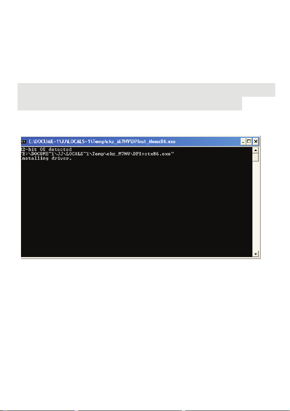
3. Install USB driver, click “USB Driver Install” menus open
automatically or browse “USB driver” folder.
“Win2000_XP_VISTA” folder “CDM 2.04.16.exe” to carry
out the installation.
D:\USB driver\Win2000_XP_VISTA\CDM 2.04.16.exe Suppose D is a CD-ROM driver)
Notice: There are Win2000_XP_VISTA and Win98_ME folders in USB driver.
older, please select what operating system you need for installation.
When installing the following picture will appear:
When the above picture appears, installation of the
driver
is finished. The CD-ROM download to the PC is
taken out of the CD-ROM driver.
5
USB
Page 8
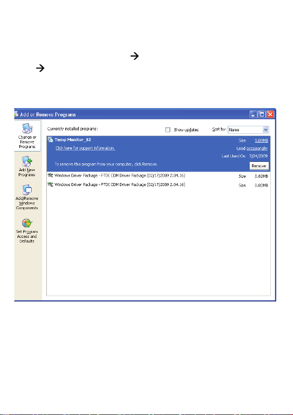
1.3 Remove Temp Monitor_S2 and USB driver
1. Please close the use software first.
2. Click “start”.
3. Click “Control Penal”
“Temp Monitor_S2” to uninstall.
4. Click “Windows Driver Package – FTDI CDM Driver
Package” to uninstall.
“Add or Remove Programs”
6
Page 9

2. On-line/download to PC
1. USB wire / RS-232 wire to connect PC and
thermometer.
2. Click “start”
“Temp Monitor_S2”.
“All Programs” “Temp Monitor_S2”
7
Page 10

3. Picture of the software.
8
Page 11
2.1 Brief introduction of every function:
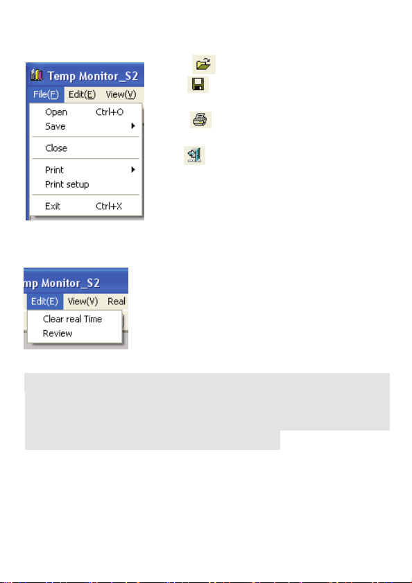
File menu:
Open : open file.
Save
: save file.
Close: Close picture while carrying out.
Print
: print file.
Print setup: Set up printer.
Exit
: Finish program.
Edit menu:
Clear real Time:
Review: The window GRAPH is
described again.
Remove record data.
Notice: Clear real Time uses the record data to
recording mode, first carry out any program recording after clicking “Stop”
to carry out record data to clear.
“Stop” please consult page 10 Real Time Data menu.
clear under
the real time
9
Page 12
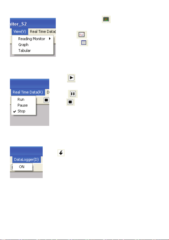
View menu:
Reading Monitor : open / close
Reading Monitor window.
Graph
Tabular
Real Time Data menu:
Run : on-line, carry out Real Time
function.
Pause
Stop
DataLogger menu:
ON : Loaded the record data of datalogger
from METER to PC.
: open / close Graph window.
: open / close Tabular window.
: Real Time record is suspended.
: off-line (off-line with Meter).
10
Page 13

Option menu:
Reading Monitor - The reading of selects and sets up
Monitor Display
Set up style, size of script, the color and background color of
the reading window.
T1 / T2 / T3 / T4 Limit (T1 / T2 / T3 / T4 critical
value restraint in setting up)
Set up warning background color and the opening and closing
of the warnings of the maximum, minimum critical value, is
not recommended using white in order to warn the
background color.
Primary button can be returned to initial selects.
11
Page 14
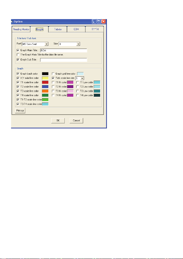
Graph - graph selects and sets up
Title font / Tick font (the style of title / the style of the
mark sets up)
Set up style of the title, subtitle and mark and size of script.
Graph- graph window picture sets up
Set up the background color of the graph window, scale line,
Hi / Low scale line, cross axle, grid color are set up, scale line
size are set up. User can select whether or not to show on the
graph window picture.
Primary button can be returned to initial selects.
12
Page 15

Tabular - The form selects and sets up
Tabular font (The style of the form sets up)
Set up the style of form and size of script.
Tabular grid (The form grid sets up)
Set up grid type, background form color and maximum,
minimum value and label color.
Primary button can be returned to initial selects.
13
Page 16

COM - The COM Port selects and sets up
Can choose to auto scan COM ports or select the COM port.
Primary button can be returned to initial selects.
14
Page 17

T1~T4
Can set T1, T2, T3 and T4 Hi / Low value, the range cannot
exceed the thermocouple type maximum / minimum value.
Primary button can be returned to initial selects.
15
Page 18

Window menu:
Language menu:
Help menu_
Open Help :open Help file
About: The edition declares.
Cascade: cascade arrange.
Horizontal: horizontal arrange.
Vertical: vertical arrange.
Arrange Icons: arrange icon.
Can choose three language, for English,
traditional Chinese and the simplified
Chinese. The default language is
English.
16
Page 19

Interval of on-line record of Real Time:
Only Real Time has this function, from 00 minute and 01
second to 59 minutes and 59 seconds.
17
Page 20

2.2 Carry out Real Time_
1. Start the meter pc function Click the RUN key on the
picture
2.The software on- line will have the following picture:
18
Page 21

3. Operation picture
19
Page 22

2.3 Brief introduction of every window function:
Reading Monitor window:
AVG: average value.
Unit: temperature unit choose, can
o
choose
The software default temperature unit
is °C; you must carry out °F record,
after carrying out RUN
readjustment Unit is oF.
Type: thermocouple Type form is
chosen; it is determined that
optional Type is set up by Meter
function.
Rel: The setting up value of Rel,
press the function key of Rel, the
window shows Rel symbol, the
showing reading is reading reduced
by the setting up value of Rel.
Limit & Hi / Low: The setting up
value of Hi Low, upper and lower limits are decided by Type chosen,
press the function key of Limit from Type, the window shows Limit
ymbol, when the reading is greater than the setting up value of Hi,
he window turns into sets up color of Hi, at the same time PC will
give out warnings. When the reading is smaller than the setting up
value of Low, the window turns into sets up color of Low, will send out
the warnings of PC at the same time.
C, oF or K.
20
Page 23

Real Time Graph window:
1) Graph Redraw Button.
2) T1, T2, T3, T4, T1-T2 and T3-T4 scale line, check items
needed to display the scale line.
3) Temperature Interval default is auto, if user needs to change the
temperature interval, the item will be canceled. User can
change temperature interval from 1 to 999.
4) Temperature coordinates start value default is auto. If the user
needs to change the start value, the checked item will be
canceled to set.
5) Set up time in the interval of scale, max 59 minutes and 59
seconds, min 0 minute and 1 second.
6) Page: max 400 pages.
21
Page 24

Tabular window
DataFile: Seat files temporarily record value; each file can
record 9999 record data points. Exceeding 9999 points will
change the new-record value file and will continue to record
automatically temporarily.
Notice: If you want to save data please select files temporarily in DataFile to
press or “Save” of File of menu.
If you want to delete a recorded file in DataFile, click the file
you want to delete, press mouse right key or choose Clear real
Time of Edit of menu. A talk window will appear prompting
you whether or not you want to delete the recorded file.
T1 / T2 / T3 / T4: T1 / T2 / T3 / T4 maximum, minimum value
of recorded value, press MAX or MIN to find the relative
recorded value in the recorded list.
22
Page 25

Search: To stop in real time, you can search for data (ex: the
6th data). Enter in the search space of 6, use mouse left key to
click the green search button. The Graph window will show a
curve marked by points, and the tabular will be highlighted.
23
Page 26

2.4 Carry out DataLogger download data:
Notice: Before making the download data of DataLogger, if you used Real
Time function, please stop Real Time first, and then carry on
download data.
1. Start DataLogger download data:
Click
of picture function keys or “ON” of DataLogger
menu.
Notice: Before making the download data of DataLogger you must stop the
meter’s PC function.
DataLogger
24
Page 27

2. The picture of download data after on-line
3. The download data finished picture
25
Page 28

4. Open download data picture
5. The download data open the picture of finishing
26
Page 29

2.5 Save files:
Notice: Before saving data, if you used Real Time function, please stop
Real Time first, and then carry on “SAVE” data.
1. Click record temporary file in DataFile then to click or
“Save” of File menu.
27
Page 30

2. Choose SaveData picture
Left side functions of picture are arranged with draw menu in
the save position. This type can be revised to change file name
or type of saved file, as being scheduled type of saving *.txt. If
you wish to change save type to *.xls, please change the
picture.
28
Page 31

3.Choose SaveBMP picture
Left side functions of picture are arranged with draw menu in
the save position. This type can be revised to change file name
or type of save file, as being scheduled type of saving *.BMP.
If you wish to change save type to *.jpg, *.png, or *.emf, please
change the picture.
29
Page 32

2.6 Open- open old file:
Notice: Before printing data, if you used Real Time function, please stop.
Real Time first, and then carry on OPEN -open old file.
1. Click record temporary file in DataFile then to click or
“Open” of File menu.
30
Page 33

2. Choose picture of file:
Press “open” on the lower right corner after choosing the file
you want to open. If the open file type is different please open
according to down picture.
31
Page 34

3. Open picture of finished
32
Page 35

2.7 Print types the file:
Notice: Before printing data, if you used Real Time function, please stop.
Real Time first, and then Print data.
1. Click record temporary file in DataFile then to click or
“Print” of File menu.
33
Page 36

2.Choose the print type
(1) Print Graph type picture.
This function prints in the Graph window picture. Choose
the printer window after clicking, then choose the type of
printer by clicking the print button.
Notice: Before printing the Graph window picture, please use Graph of
Option to set up the window first, then make bottom into white or other
light color.
(2) Print Tabular of form content:
This function prints the form content at Tabular window
Choose the printer window after clicking, by choosing the
type of printer then click the print button.
34
Page 37

2.8 Close the picture while carrying out:
Notice: Before closing the picture while carrying out, if you used the Real time
function, then stop Real Time first, and then carry the picture closing while
carrying out.
1. Click Close in menu of File.
35
Page 38

2. Picture after carry out.
36
Page 39

2.9 Language
Notice 1 : Before changing the language, if you used Real Time function,
please stop Real Time first, and then change the language.
Notice 2 : If your operating system does not support Chinese characters then
there is no need to change the language.
1. Click Traditional Chinese in menu of File.
37
Page 40

2. If you want to change the language, please click the “YES”
button.
3. This will end the program and automatically return you to
the computer screen.
If you want to replace the screen back to the original
language, please repeat the above action.
38
Page 41

NOTES:
39
Page 42

NOTES:
40
Page 43

FOR WARRANTY RETURNS, please have
the following information available BEFORE
contacting OMEGA:
1. Purchase Order number under which the
product was PURCHASED,
2. Model and serial number of the product
under warranty, and
3. Repair instructions and/or specific
problems relative to the product.
FOR NON-WARRANTY REPAIRS,
consult
OMEGA for current repair charges. Have the
following information available BEFORE
contacting OMEGA:
1. Purchase O rd e r nu mb er t o c over the COST
of the repair,
2. Model and serial number of the product, and
3. Repair instructions and/or specific problems
relative to the product.
OMEGA’s policy is to make running changes, not model changes, whenever an improvement is
possible. This affords our customers the latest in technology and engineering.
OMEGA is a registered trademark of OMEGA ENGINEERING, INC.
© Copyright 2009 OMEGA ENGINEERING, INC. All rights reserved. This document may not be copied,
photocopied, reproduced, translated, or reduced to any electronic medium or machine-readable form, in
whole or in part, without the prior written consent of OMEGA ENGINEERING, INC.
WARRANTY / DISCLAIMER
OMEGA ENGINEERING, INC. warrants this unit to be free of defects in materials and
workmanship for a period of 13 months from date of purchase. OMEGA’s Warranty adds an
additional one (1) month grace period to the normal one (1) year product warranty to cover
handling and shipping time. This ensures that OMEGA’s customers receive maximum coverage
on each product.
If the unit malfunctions, it must be returned to the factory for evaluation. OMEGA’s Customer
Service Department will issue an Authorized Return (AR) number immediately upon phone or
written request. Upon examination by OMEGA, if the unit is found to be defective, it will be
repaired or replaced at no charge. OMEGA’s WARRANTY does not apply to defects resulting
from any action of the purchaser, including but not limited to mishandling, improper interfacing,
operation outside of design limits, improper repair, or unauthorized modification. This
WARRANTY is VOID if the unit shows evidence of having been tampered with or shows
evidence of having been damaged as a result of excessive corrosion; or current, heat, moisture
or vibration; improper specification; misapplication; misuse or other operating conditions
outside of OMEGA’s control. Components in which wear is not warranted, include but are not
limited to contact points, fuses, and triacs.
OMEGA is pleased to offer suggestions on the use of its various products. However,
OMEGA neither assumes responsibility for any omissions or errors nor assumes
liability for any damages that result from the use of its products in accordance with
information provided by OMEGA, either verbal or written. OMEGA warrants only that
the parts manufactured by the company will be as specified and free of defects.
OMEGA MAKES NO OTHER WARRANTIES OR REPRESENTATIONS OF ANY KIND
WHATSOEVER, EXPRESSED OR IMPLIED, EXCEPT THAT OF TITLE, AND ALL IMPLIED
WARRANTIES INCLUDING ANY WARRANTY OF MERCHANTABILITY AND FITNESS
FOR A PARTICULAR PURPOSE ARE HEREBY DISCLAIMED. LIMITATION OF LIABILITY:
The remedies of purchaser set forth herein are exclusive, and the total liability of
OMEGA with respect to this order, whether based on contract, warranty, negligence,
indemnification, strict liability or otherwise, shall not exceed the purchase price of the
component upon which liability is based. In no event shall OMEGA be liable for
consequential, incidental or special damages.
CONDITIONS: Equipment sold by OMEGA is not intended to be used, nor shall it be used: (1) as
a “Basic Component” under 10 CFR 21 (NRC), used in or with any nuclear installation or activity;
or (2) in medical applications or used on humans. Should any Product(s) be used in or with any
nuclear installation or activity, medical application, used on humans, or misused in any way,
OMEGA assumes no responsibility as set forth in our basic WARRANTY/ DISCLAIMER language,
and, additionally, purchaser will indemnify OMEGA and hold OMEGA harmless from any liability
or damage whatsoever arising out of the use of the Product(s) in such a manner.
RETURN REQUESTS / INQUIRIES
Direct all warranty and repair requests/inquiries to the OMEGA Customer Service Department.
BEFORE RETURNING ANY PRODUCT(S) TO OMEGA, PURCHASER MUST OBTAIN AN
AUTHORIZED RETURN (AR) NUMBER FROM OMEGA’S CUSTOMER SERVICE DEPARTMENT (IN
ORDER TO AVOID PROCESSING DELAYS). The assigned AR number should then be marked on
the outside of the return package and on any correspondence. The purchaser is responsible for
shipping charges, freight, insurance and proper packaging to prevent breakage in transit.
Page 44

Where Do I Find Everything I Need for
Process Measurement and Control?
OMEGA…Of Course!
Shop online at omega.com
sm
M4831/1109
TEMPERATURE
䡺⻬
Thermocouple, RTD & Thermistor Probes, Connectors, Panels & Assemblies
䡺⻬
Wire: Thermocouple, RTD & Thermistor
䡺⻬
Calibrators & Ice Point References
䡺⻬
Recorders, Controllers & Process Monitors
䡺⻬
Infrared Pyrometers
PRESSURE, STRAIN AND FORCE
䡺⻬
Transducers & Strain Gages
䡺⻬
Load Cells & Pressure Gages
䡺⻬
Displacement Transducers
䡺⻬
Instrumentation & Accessories
FLOW/LEVEL
䡺⻬
Rotameters, Gas Mass Flowmeters & Flow Computers
䡺⻬
Air Velocity Indicators
䡺⻬
Turbine/Paddlewheel Systems
䡺⻬
Totalizers & Batch Controllers
pH/CONDUCTIVITY
䡺⻬
pH Electrodes, Testers & Accessories
䡺⻬
Benchtop/Laboratory Meters
䡺⻬
Controllers, Calibrators, Simulators & Pumps
䡺⻬
Industrial pH & Conductivity Equipment
DATA ACQUISITION
䡺⻬
Data Acquisition & Engineering Software
䡺⻬
Communications-Based Acquisition Systems
䡺⻬
Plug-in Cards for Apple, IBM & Compatibles
䡺⻬
Datalogging Systems
䡺⻬
Recorders, Printers & Plotters
HEATERS
䡺⻬
Heating Cable
䡺⻬
Cartridge & Strip Heaters
䡺⻬
Immersion & Band Heaters
䡺⻬
Flexible Heaters
䡺⻬
Laboratory Heaters
ENVIRONMENTAL MONITORING AND CONTROL
䡺⻬
Metering & Control Instrumentation
䡺⻬
Refractometers
䡺⻬
Pumps & Tubing
䡺⻬
Air, Soil & Water Monitors
䡺⻬
Industrial Water & Wastewater Treatment
䡺⻬
pH, Conductivity & Dissolved Oxygen Instruments
 Loading...