

Page 1
JUNE 3, 2010
Re-Order from
omegamation.com
Omegamation
TM
1-888-55-OMEGA
1-888-55-66342
1-888-55-66342
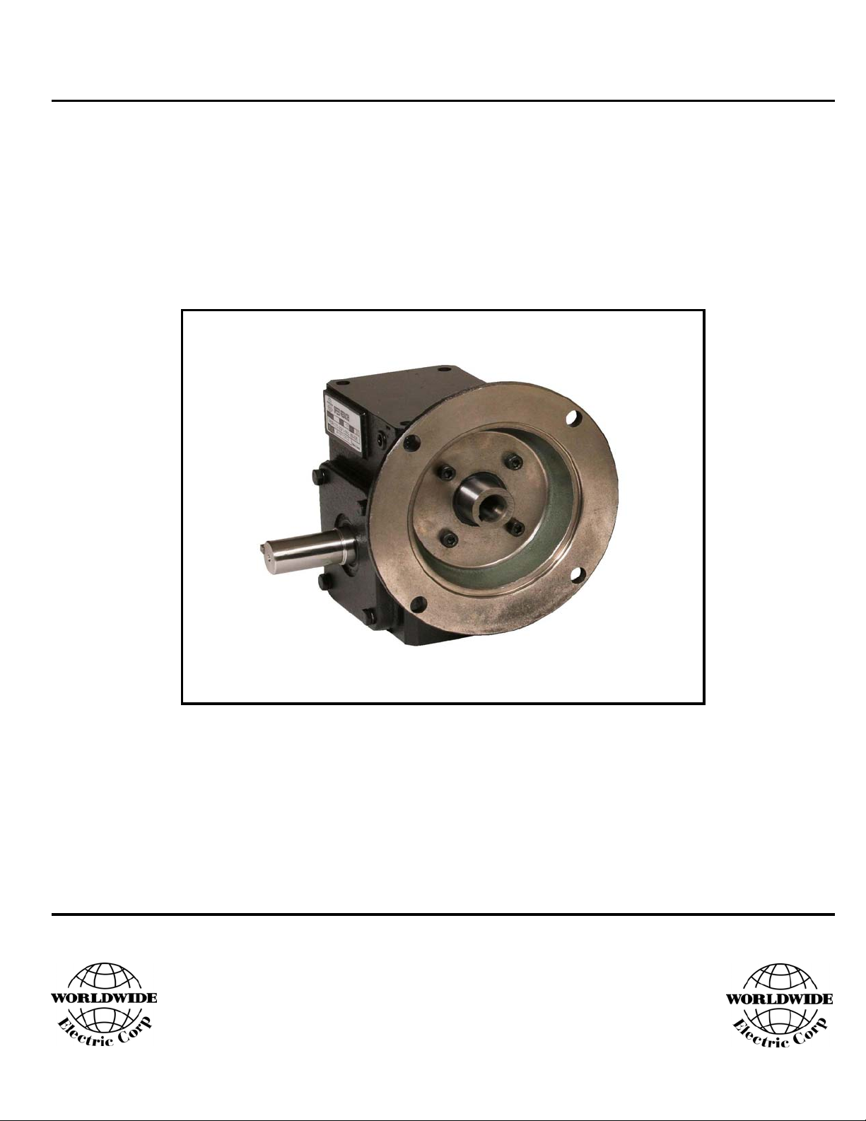
INSTALLATION AND
MAINTENANCE MANUAL
HdR SERIES PROGRAM
WORM GEAR SPEED REDUCERS
WorldWide Electric Corporation
Phone: 1-800-808-2131 Ext. 8
Fax: 1-800-711-1616 Ext. 8
Website: www.worldwideelectric.net
Page 2

WORLDWIDE ELECTRIC CORPORATION
HdR SERIES PROGRAM - WORM GEAR SPEED REDUCERS
TABLE OF CONTENTS
SECTION I: MOUNTING INSTRUCTIONS PAGE 1
SECTION II: VENT PLUG INFORMATION PAGE 1
SECTION III: ENGINEERING DATA PAGE 2
SECTION IV: LUBRICATION SCHEDULE PAGE 3
SECTION V: LIMITED WARRANTY PAGE 4
WorldWide Electric Corporation
Phone: 1-800-808-2131 Ext. 8
Fax: 1-800-711-1616 Ext. 8
Website: www.worldwideelectric.net
Page 3

WORLDWIDE ELECTRIC CORPORATION
HdR SERIES PROGRAM - WORM GEAR SPEED REDUCERS
MOUNTING INSTRUCTIONS / GENERAL INFORMATION
MOUNTING INSTRUCTIONS: VENT PLUG INFORMATION:
1. Leave protective sleeves on shafts for safe handling of speed All WorldWide HdR Series Worm Gear Reducers are tested
reducer during installation. The sleeves are provided also to and then filled with Mobile SHC 634 synthetic lube. WorldWide
protect your hands from potential sharp edges and keyways. worm gear reducers will not have the vent plug installed.
2. Align all shafts accurately. Improper alignment can result in Remove the solid plug and install the pressure vent plug
failure. Use flexible couplings to help compensate for slight according to the following:
misalignment.
1. Vented plug must be installed in the uppermost position.
3. When mounting, use maximum possible bolt size and secure
reducer to a rigid foundation. Periodic inspection of all bolts 2. For all mounting positions where the vented plug is located
is recommended. in a horizontal plane, the vent hole must be pointed upward.
4. Auxiliary drive components (such as sprockets, gears and 3. For all mounting positions where the vented plug is located
pulleys) should be mounted on the shafts as close as possible in a vertical plane, the vent hole must point toward the center
to the housing to minimize effects of overhung loads. Avoid of the housing.
force fits that might damage bearings or gears.
5. For hollow-shaft speed reducers, place speed reducer as close
as possible to supporting bearing on driven shaft. Spot-drill
driven shaft for setscrews in severe applications.
6. Check and record gear backlash at installation and again at Or Self-Locking Devices. If These Features Are Required,
regular intervals. This should be done by measuring the A Properly Sized Independent Holding Device Should Be
rotary movement of the output shaft (rotating alternately Utilized.
clockwise and counterclockwise) at a suitable radius while
holding the input shaft stationary. Gears should be replaced - Depending Upon Gear Geometry and Operating Conditions,
when the backlash exceeds four times the measurement taken Worm Gear Reducers May Or May Not Backdrive. Special
at installation. Consideration Should Be Given To High Inertia Loads
7. Gear drives are rated for 1750 input RPM and Class 1 Service For Further Details.
(Service Factor 1.00), using Mobile SHC 634 synthetic lube.
8. Initial operating temperatures may be higher than normal Accommodate Motor Driving, Brake and Inertia Loads
during the break-in period of the gear set. For maximum To Prevent The Braking Torque Or Inertia Loads From
life do not allow the speed reducer to operate continuously Exceeding The Motor Rating.
above 225°F at the gear case. In the event of overheating,
check for overloads or high ambient temperatures. Keep
shafts and vent plugs clean to prevent foreign particles from
entering seals or gear housings.
CAUTION:
- Worm Gear Reducers Are Not To Be Considered Fail Safe
Connected To The Reducer Output Shaft. Consult Factory
- Reducers Driven By Brake Motors Must Be Sized To
INSTALLATION AND
MAINTENANCE MANUAL
PAGE 1
Page 4

y
WORLDWIDE ELECTRIC CORPORATION
HdR SERIES PROGRAM - WORM GEAR SPEED REDUCERS
ENGINEERING DATA
CLASSES OF SERVICE:
All WorldWide HdR Series Worm Gear Reducers Are For A 1.00 Service Factor Or Class I Service. A 1.00 Service Factor Applied When The
Use Of The Reducer Is For Continuous Service Free From Recurrent Shock Loading and Does Not Exceed 10 Hours Per Day. When Operating
Conditions Are Different From Those Described Above, The Input Horsepower and Torque Ratings Shown Must Be Divided By The
Appropriate Service Factor Indicated In The Table Below. The Catalog Ratings May Be Used Without Adjustments If The Actual Driven
Machine Horsepower and Torque Requirements Are Multiplied By The Appropriate Service Factor Indicated In The Table Below.
SERVICE FACTORS:
Service Factors For Electric and Hydraulic Motors
(For Service Factors For Single Or Multi-Cylinder Engines, See Below)
Duration Of Service
(Hours Per Day)
Occasional 1/2 Hour
Less Than 3 Hours
3 - 10 Hours
Over 10 Hours
* Unspecified Service Factors Should Be 1.00 Or Agreed Upon By The User and Manufacturer
Conversion Table For Single Or Multi-Cylinder Engines
To Find Equivalent Single Or Multi-Cylinder Service Factor
Hydraulic Or
Electric Motor
1.00 1.50 1.25
1.25 1.75 1.50
1.50 2.00 1.75
1.75 2.25 2.00
2.00 2.50 2.25
Uniform
Load
--- * --- * 1.00 1.25
1.00 1.00 1.25 1.50
1.00 1.25 1.50 1.75
1.25 1.50 1.75 2.00
Single Cylinder
Engines
Moderate
Shock
Multi-Cylinder
Engines
Heav
Shock
Extreme
Shock
Normal Starting Or Occasional Peak Loads, Two Or Three Times Per Day, Up To 300% Of Catalog Rating At 1800 RPM Are Permissible.
If Either The Frequency Or The Magnitude Of These Loads Exceed The Above Limits, A Higher Service Factor Is Required and The
Application Should Be Referred To The Factory.
INSTALLATION AND
MAINTENANCE MANUAL
PAGE 2
Page 5

WORLDWIDE ELECTRIC CORPORATION
HdR SERIES PROGRAM - WORM GEAR SPEED REDUCERS
LUBRICATION SCHEDULE
Recommended
Lubricant
AGMA Rating
ISO Grade
Getty Refining Co.
Lubrication Engr. Inc.
Lubriplate
Shell Oil Co.
Texaco Inc.
CAUTION:
NOT USE Lubricants That Contain Sulphur and / or Chlorine Which Are Corrosive To Bronze Gears. Extreme Pressure Lubricants,
DO
In Some Cases, Contain Materials That Are Toxic. Avoid Use Of These Lubricants Where They Can Result In Harmful Effects.
Lubricants Are Compounded For Use In Worm Gears. Some Contain Non-Corrosive, Extreme Pressure Additives.
-30° To 225°F
-34° To 107°C
Synthetic 7 7 EP 8 8 EP
320 / 460 460 460 680 680
Mobil
SHC 634
Synthetic
Synthetic
Recommendation
Is Exclusively For
Mobil SHC 634
Cylinder Oil
Almasol 608 Almasol 609
Omala J460 Omala 460
40° To 90°F
4.4° To 32.2°C
Mobil
600W
--- ---
---
---
---
Veedol Asreslube
95
---
Mobil Extra
Hecla Super
Cylinder Oil
SPO-288---
Omala J460
80° To 125°F
26.7° To 51.7°C
--- Meropa 680Meropa 460
Mobilgear
634
Veedol Asreslube
98
---
---
Omala 680
CAUTION:
Oil Changes Are Recommended When Operating Continuously, At High Temperatures Or Under Conditions Of Extreme Dirt Or Dust.
Reducer
Size
Position A B C D E F
133 5.82 Ounces 8.52 Ounces 8.52 Ounces 7.62 Ounces 6.92 Ounces 6.92 Ounces
154 11.64 Ounces 15.74 Ounces 15.74 Ounces 14.44 Ounces 13.54 Ounces 13.54 Ounces
175 11.64 Ounces 18.74 Ounces 18.74 Ounces 17.24 Ounces 15.14 Ounces 15.14 Ounces
206 19.41 Ounces 28.41 Ounces 28.41 Ounces 26.71 Ounces 21.81 Ounces 21.81 Ounces
237 24.07 Ounces 35.17 Ounces 35.17 Ounces 33.77 Ounces 29.67 Ounces 29.67 Ounces
262 34.55 Ounces 48.25 Ounces 48.25 Ounces 45.85 Ounces 41.05 Ounces 41.05 Ounces
325 73.75 Ounces 102.55 Ounces 102.55 Ounces 97.75 Ounces 88.05 Ounces 88.05 Ounces
Too Much Oil Will Cause Overheating and Too Little Will Result In Gear Failure. Check Oil Level Regularly. More Frequent
VERTICAL INPUT SHAFTHORIZONTAL INPUT SHAFT
NOT RECOMMENDED
Approximate Capacity
(Ounces)
Page 6

WORLDWIDE ELECTRIC CORPORATION
Re-Order from
omegamation.com
Omegamation
TM
1-888-55-OMEGA
1-888-55-66342
1-888-55-66342
HdR SERIES PROGRAM - WORM GEAR SPEED REDUCERS
LIMITED WARRANTY
WorldWide Electric Corporation (The Company) Warranties It's Products To Be Free From
Defects In Materials Or Workmanship To The Original Purchaser For A Period Of One (1)
Year From The Date Of Purchase. For This Warranty To Be Effective, This Product Must
Be Installed, Used and Maintained By The Original Purchaser In Accordance With Good
Industry Standards. The Warranty Does Not Cover Normal Wear, Tear and Erosion From
Use, Mis-use, Abuse Or Corrosion.
In The Event Of Failure, It Shall Be The Responsibility Of The Original Purchaser To Notify
The Company Either In Writing Or By Telephone To Make Arrangements For The Correction
Of The Problem. The Purchaser Shall Be Responsible For Transportation Charges Connected
With The Return, Exchange Or Repair Of Parts. Returns Found Defective Upon Inspection
By Our Warranty Department Or Authorized Warranty Service Agent Will Be Replaced Free
Of Charge.
The Company Shall Not Be Liable For Any Labor Cost Connected With The Replacement
Of The Equipment, The Replacement Of The Parts Or Adjustments To The Equipment By
The Purchaser Or Their Contractor Without The Company's Prior Written Approval.
The Company, As The Exclusive Remedy Under This Warranty, Shall At It's Option Repair
Or Replace Defective Items Or, If Agreed Upon, Refund The Purchase Price Less Reasonable
Allowance For Depreciation In Exchange For The Product.
THE COMPANY MAKES NO OTHER WARRANTIES AND ALL IMPLIED OR
EXPRESSED WARRANTIES AND REPRESENTATIONS, EXCEPT THAT OF TITLE,
ARE DISCLAIMED. ALL IMPLIED WARRANTIES INCLUDING MERCHANTABILITY
AND FITNESS FOR A PARTICULAR PURPOSE OR USE BUT NOT LIMITED TO
JUST THOSE THAT ARE DISCLAIMED. LIABILITY FOR CONSEQUENTIAL,
INCIDENTAL OR SPECIAL DAMAGES AND LOSSES UNDER ANY AND ALL
WARRANTIES WHETHER IN CONTRACT, TORT OR OTHERWISE ARE EXCLUDED
TO THE EXTENT EXCLUSION IS PERMITTED BY LAW.
INSTALLATION AND
MAINTENANCE MANUAL
PAGE 4
 Loading...