

Page 1
User’s Guide
FPUDVS2000 SERIES
Shop online at
Omega.com
e-mail: info@omega.com
For latest product manuals:
Omegamanual.info
Digital Variable Speed Peristaltic Injector Pump
With external signal inputs
Operating Manual
Page 2

OMEGAnet Online Service Internet e-mail
Omega.com info@omega.com
Servicing North America:
U.S.A.: One Omega Drive, P.O. Box 4047
ISO 9001 Certified Stamford, CT 06907-0047
TEL: (203) 359-1660 FAX: (203) 359-7700
E-mail: info@omega.com
Canada: 976 Bergar
Laval (Quebec) H7L5A1, Canada
TEL: (514) 856-6928 FAX: (514) 856-6886
E-mail: info@omega.ca
For immediate technical or application assistance:
U.S.A. And Canada: Sales Service: 1-800-826-6342 / 1-800-TC-OMEGA
Customer Service: 1-800-622-2378 / 1-800-622-BEST
Engineering Service: 1-800-872-9436 / 1-800-USA-WHEN
Mexico: En Espanol: (001) 203-359-7803 e-mail: espanol@omega.com
FAX: (001) 203-359-7807 info@omega.com.mx
Service Europe:
Benelux: Postbus 8034, 1180 LA Amstelveen, The Netherlands
TEL: +31 (0)20 3472121 FAX: +31 (0)20 6434643
Toll Free in Benelux: 0800 0993344
E-mail: sales@omega.fr
Czech Republic: Frystatska 184, 733 01 Karvina, Czech Republic
Tel: +420 (0)59 6311899 FAX: +420 (0)59 6311114
Toll Free: 0800-1-66342 e-mail: info@omegashop.cz
France: 11, rue Jacques Cartier, 78280 Guyancourt, France
TEL: +33 (0)1 61 37 2900 FAX: +33 (0)1 30 57 5427
Toll Free in France: 0800 466 342
E-mail: sales@omega.fr
Germany/Austria: Daimlerstrasse 26, D-75392 Deckenpfronn, Germany
TEL: +49 (0)7056 9398-0 FAX: +49 (0)7056 9398-29
Toll Free in Germany: 0800 639 7678
E-mail: info@omega.de
United Kingdom: One Omega Drive, River Bend Technology Centre
ISO 9002 Certified Northbank, Irlam, Manchester
M44 5BD United Kingdom
TEL: +44 (0)161 777 6611 FAX: +44 (0)161 777 6622
Toll Free in United Kingdom: 0800-488-488
E-mail: sales@omega.uk
It is the policy of OMEGA Engineering, Inc. To comply with all worldwide safety and EMC/EMI regulations that apply. OMEGA is constantly pursuing
certification of its products to the European New Approach Directives. OMEGA will add the CE mark to every appropriate device upon certification.
The information contained in this document is belived to be correct, but OMEGA accepts no liability for any erroes it contains, and reserves the right to alter specifications
without notice. WARNING: These products are not designed for usein, and should not be used for, human applications.
Page 3

TABLE OF CONTENTS
SECTION HEADING PAGE
1 Introduction 2
2 Specifications 3
3 Features 3
4 How to install the pump 4
4.1 Mounting location 4
4.2 Electrical connections 6
4.3 How to install the tubing and fittings 8
5 How to operate the pump 9
5.1 Description of Pump Output Adjustment Controls 9
5.2 Mode 1 - Manually Adjusting the output 10
5.3 Mode 2 - 4-20 mA input 10
Page 2
5.4 Mode 3 - 0-10 VDC input 12
5.5 Mode 4 - Frequency/Pulse (Hz) input 13
6 Alarms 14
6.1 Tube Failure Detection (TFD) system 14
7 How to maintain the FPUDVS2000 15
7.1 Routine inspection and cleaning 15
7.2 How to clean and lubricate the FPUDVS2000 15
7.3 500 hour service warning timer 15
7.4 How to replace the pump tube 16
Replacement parts drawing 17
Replacement parts list 18
1.0 Introduction
Congratulations on purchasing the pump variable speed Peristaltic Metering Pump. The pump
is designed to inject chemicals into piping systems. The pump has been tested by NSF
International for use with 12 ½% Sodium Hypochlorite. The pump is equipped with external
input control circuitry which allows the pumps output to be externally controlled by either a 420mA input signal, a 0-10V DC input signal or a pulsed frequency input signal.
Page 4
2.0 Specifications
Maximum Working Pressure 100 psig / 6.9 bar*
Maximum Fluid Temperature 130 F / 54 C
Ambient Temperature Range 14 to 110 F / -10 to 43 C
Duty Cycle Continuous
Maximum Solids 50% by volume
Maximum Viscosity 5,000 Centipoise
Maximum Suction Lift up to 30 ft. water
Power Requirements 115V60Hz, 220V50Hz, 230V60Hz
Shipping Dimensions 18” x 14” x 10”
Shipping Weight 14 lb.
Page 3
o o
o o
3.0 Features
!
Peristaltic Pump Tube does not require valves.
!
High outlet pressure capability of 100 psig.*
!
High inlet suction lift capability of 30 feet.
!
Tube Failure Detection (TFD) system (patent
pending).
!
Quick-Disconnect inlet and outlet fittings available.
!
Easy servicing.
!
Includes suction tube strainer, tube weight, suction tubing, discharge tubing and injection fitting
with internal back-flow check valve and mounting hardware.
!
Digital electronic feed rate control.
!
Pump Tube failure warning timer.
!
20:1 adjustment turn down ratio.
!
Corrosion proof Valox housing.
!
Tamper resistant electronic control panel cover.
!
Output verification sensor system.
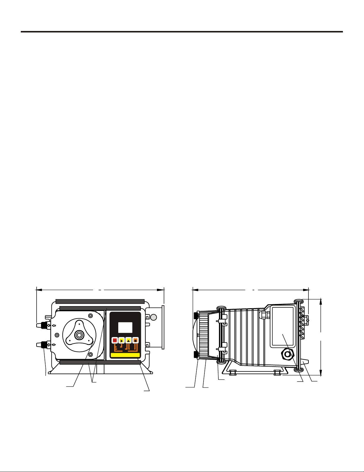
1
9
2
VARIABLE SPEED PUMP
RUN
STANDBY
1-MANUAL
PRIME
RESETSERVICE
FIELD
2- 4-20mA
PROGRAM
INPUTMODES
RUN
PROGRAM
STAND-BY
PRIME
MINIMUM
MAXIMUM
DIGIT MODE
DISPLAY
3- 0-10VDC 4- PULSE (Hz)
1
9
8
6.0
Pumptube
Assembly
Rotor
Assembly
Slide Clamps**
Control
Pumphead
Cover
Control Cover
Pumphead
* Most models.
** Slide both top & bottom clamps to the left only far enough to open the control cover.
FIG. 3.0 PARTS LOCATOR DRAWING
Junction Box
Rear Plate
Page 5
4.0 How To Install the pump
CAUTION: PROPER EYE AND SKIN PROTECTION MUST BE WORN WHEN
INSTALLING AND SERVICING THE FPUDVS2000
Note: All diagrams are strictly for guideline purposes only. Always consult an expert before
installing the pump into specialized systems.
The pump should be serviced by qualified persons only.
4.1 Mounting Location
Choose an area located near the chemical supply tank, chemical injection point and electrical
supply. Although the pump is designed to withstand outdoor conditions, a cool, dry, well
ventilated location is recommended. Install the pump where it can be easily serviced.
!
Mount the pump to a secure surface or wall using the enclosed hardware. Wall mount to a
solid surface only. Mounting to drywall with anchors is not recommended.
!
Keep the outlet (discharge) tubing as short as possible. Longer tubing increases the back
pressure at the pump tube.
Page 4
!
Do not mount the pump directly over your chemical container. Chemical fumes may damage
the unit. Mount the pump off to the side or at a lower level than the chemical container.
!
Mounting the pump lower than the chemical container will gravity feed the chemical into the
pump. This “flooded suction” installation can reduce the time required to prime the pump.
Install a shut-off valve, pinch clamp or other means to halt the gravity feed to the pump during
servicing.
!
Your solution tank should be sturdy. Keep the tank covered to reduce fumes.
!
Be sure your installation does not constitute a cross connection with the drinking water supply.
Check your local plumbing codes.
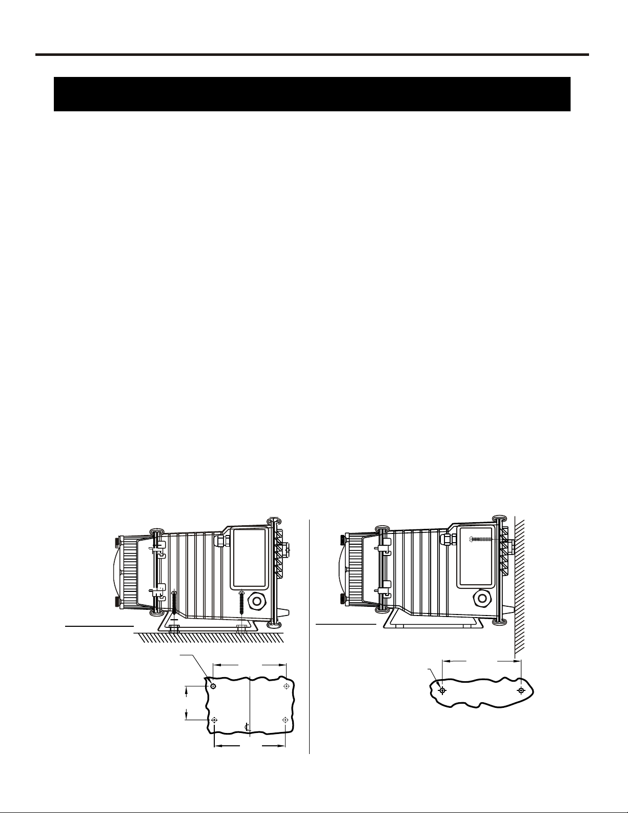
Floor Mount
Wall Mount
Drill .156 Dia. (5/32)
For Self-Tap Screw
#10 X 1” Phillips Steel
4 Places
7-5/8”
3-1/2”
7-3/8”
Drill .156 Dia. (5/32)
For Self-Tap Screw
#10 X 1” Phillips Steel
Note: For wall-mounting, recommend drill & thread into
solid wood only.
FIG. 4.0 INJECTOR MOUNTING
8-3/16”
2 Places
Page 6
1
2
3
5
4 6
7
8
9
10
Page 5
7
RUN
STANDBY
1-MANUAL
VARIABLESPEEDPUMP
MODE
%SPEED
1000
ALARM
FIELD
PRIME
RESETSERVICE
2-4-20mA
RUN
1
PROGRAM
VDC
mA Hz
STAND-BY
PRIME
MINIMUM
SERVICE
MAXIMUM
DIGIT MODE
DISPLAY
PROGRAM
INPUTMODES
3-0-10VDC 4-PULSE(Hz)
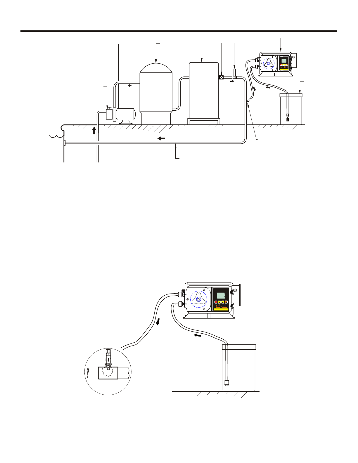
Pool
1. Strainer 6. Flowmeter
2. Circulation Pump 7. Injector
3. Filter 8. Solution Tank
4. Heater 9. Injection Fitting
5. Check Valve 10. Return Line
FIG. 4.1 SWIMMING POOL INSTALLATION
Discharge
¼"&½"NPTInjector
FIG. 4.2 TYPICAL INSTALLATION
Tube
Suction
Tube
VARIABLESPEED PUMP
MODE
%SPEED
1000
ALARM
FIELD
RUN
STANDBY
PRIME
RESET SERVICE
INPUTMODES
2-4-20mA
1-MANUAL
PROGRAM
mA Hz
1
VDC
SERVICE
DIGIT MODE
3-0-10VDC 4-PULSE(Hz)
RUN
PROGRAM
STAND-BY
PRIME
MINIMUM
MAXIMUM
DISPLAY
Chemical
Container
Page 7

4.2 Electrical Connections
4.2.1 Input Power Connections -
Be certain to connect the pump to the proper supply voltage. Using the incorrect voltage will
damage the pump and may result in injury. The voltage requirement is printed on the pump
serial label.
WARNING-RISK OF ELECTRICAL SHOCK
Jumper pins on the circuit board are factory preset for the correct voltage. See Fig. 4.4, page 7
for details.
The pump is supplied with a ground wire conductor and a grounding type attachment plug
(power cord). To reduce the risk of electric shock, be certain that the power cord is connected
only to a properly grounded, grounding type receptacle.
Note: When in doubt regarding your electrical installation, contact a licensed electrician.
4.2.2 External Input Signal Connections -
Page 6
The pump will accept any one of three different types of external input signals; 4-20 mA, 0-10
VDC, or frequency. The 4-20mA and 0-10 VDC loops must be powered. Two types of frequency inputs, AC sine waves (magnetic coils type outputs) and Digital Square waves (Hall
Effect signals, contact closures), are acceptable. A jumper plug located on the circuit board is
factory pre-set for AC sine wave signals, the jumper must be re-positioned when digital square
wave signals are being used. (See Fig. 4.4, page 7, “Hz input jumper settings”)
All wiring connections are to be made inside of the junction box located on the side of the
pump. A liquid-tite connector is supplied and should be used for the external signal cable. The
signal input wires are color coded to the type of signal being used.
INPUT SIGNAL TYPE
4-20 mA
0-10 V DC
AC sine wave, Digital square wave
POSITIVE
WIRE COLOR
BLUE (non-powered)
ORANGE (non-powered)
WHITE
NEGATIVE
WIRE COLOR
BLACK
BLACK
BLACK
FIG. 4.3 WIRING CHART - INPUT SIGNAL WIRE COLORS
Page 8

SIGNAL INPUT MODES / FUNCTIONS & WIRING COLOR CODES
Page 7
INPUT MODE / FUNCTION
MANUAL
4-20 mA
0-10 VDC
FREQUENCY
ALARM RELAY
FLOW VERIFICATION SENSOR
(Digital square waves)
MOTOR ON SIGNAL
EXTERNAL INPUT CABLE
ACCEPTABLE CABLE JACKET RANGE:
RED (+20VDC)
BLACK (Ground)
BLUE (4-20 mA input)
ORANGE (0-10 VDC input)
WHITE (frequency input)
YELLOW (verification sensor input)
BROWN (motor-on contact output)
PURPLE X2 (alarm relay contacts)
.118 - .255 INCH
.( 3,0 - 6,5 MM)
JUNCTION BOX
WIRES REQUIRED
NO CONNECTIONS
BLUE (+) & BLACK (-)
ORANGE (+) & BLACK (-)
WHITE (+) & BLACK (-)
PURPLE & PURPLE
RED (+ 20VDC) & BLACK (-) & YELLOW (signal)
BROWN (+) & BLACK (-)
Hz INPUT JUMPER SETTINGS
(open - factory default)
AC LINE VOLTAGE SETTINGS
Located under connector
AC sine waves
Jumper Not Installed
Digital square waves
Jumper Installed
INPUT SIGNAL CONNECTOR
7 wire bundle
LIQUID-TIGHT
CONNECTOR
ALARM OUTPUT
(CONTACT CLOSURE)
connect 2-conductor plug to either
normally open (NO) (factory default)
or normally closed (NC) side of receptacle.
1 AMP MAX @ 125VAC (24VDC)
TUBE FAILURE SENSOR PROBE INPUT
Connect 2-conductor plug to receptacle.
2 Grey wires connect to pump head sensors.
RED (+)
DC
MOTOR
BLACK (-)
Ground (green)
MOTOR
RED (+)
MOTOR
BLACK (-)
NC
NO
AC LINE
NEUTRAL
110
0
22
101
One Jumper Installed
TS
ROBPE
.187 push tab connectors
1 AMP
250VAC
AC LINE
HOT
Common
Earth Ground (green)
230 VAC
on center position
(ends open)
Two Jumpers Installed
on end positions
(no open pins)
THERMAL SWITCH
2 conductors
PROTECTOR FUSE
1 Amp, 250 Volt AC
(Littlefuse #239001
or Equivalent)
Hot
AC
Input
Power
115 VAC
FIG. 4.4 WIRING DIAGRAM - CIRCUIT BOARD
Page 9

Page 8
4.3 How To Install the Tubing and Fittings
CAUTION: PROPER EYE AND SKIN PROTECTION MUST BE WORN WHEN
INSTALLING AND SERVICING THE FPUDVS2000
4.3.1 Inlet Tubing - Locate the inlet fitting of the Pump Tube, see fig 4.6. Remove the tube nut.
Push the clear PVC suction tubing onto the compression barb of the fitting. Use the tube nut to
secure the tube. Hand tighten only.
4.3.2 Strainer -Trim the inlet end of the suction tubing so that the strainer will rest
approximately two inches from the bottom of the solution tank. This will prevent
sediment from clogging the strainer. Slip the ceramic weight over the end of
the suction tube. Press the strainer into the end of the tube. Secure the
ceramic weight to the strainer. Drop the strainer into the solution tank.
4.3.3 Outlet Tubing - Locate the outlet fitting of the Pump Tube, see fig 4.6.
Remove the tube nut. Push the opaque outlet (discharge) tubing onto the
compression barb of the fitting. Use the tube nut to secure the tube. Hand
tighten only. Trim the other end of the outlet tube leaving only enough slack to
connect it to the injection/check valve fitting. Increasing the outlet tube length
increases the pressure at the pump tube, particularly with viscous fluids.
Keep the outlet tube as short as possible.
Tubing
Suction 3/8"
Ceramic
Weight
FPU2000-CW
Foot
Strainer
# 90002-200
FIG. 4.5
4.3.4 Injection/Check Valve Fitting Installation -
The Injection/Check valve fitting is designed
to install directly into either 1/4” or 1/2”
female pipe threads. This fitting will require
periodic cleaning, especially when injecting
fluids that calcify such as sodium
hypochlorite. These lime deposits and other
build ups can clog the fitting increasing the
back pressure and interfering with the check
valve operation. See section 7.0.
Install the Injection/Check valve directly into
the piping system. Do not use a pipe stud
with a tee for insertion of the injection valve.
The solution must inject directly into the flow
stream.
Use Teflon thread sealing tape on the pipe
threads. Push the opaque outlet (discharge)
tubing onto the compression barb of the
Injection/Check valve fitting. Use the tube
nut to secure the tube. Hand tighten only.
Outlet Adapter
Inlet Adapter
Pump Head
VARIABLE SPEED PUMP
MODE
mA Hz
% SPEED
1000
ALARM
FIELD
RUN
STANDBY
PRIME
RESETSERVICE
PROGRAM
INPUTMODES
2- 4-20mA
1- MANUAL
FIG. 4.6
RUN
1
PROGRAM
VDC
STAND-BY
PRIME
MINIMUM
SERVICE
MAXIMUM
DIGIT MODE
DISPLAY
3- 0-10VDC 4 - PULSE (Hz)
EXPLODED VIEW
FIG. 4.7 INJECTION FITTING INSTALLATION AND EXPLODED VIEW
Page 10

5.0 How To Operate The Pump
5.1 Description of Pump Output Adjustment Controls -
Open the control panel door by sliding the upper and lower slide
clamps to the left. FIG. 5.2
!
RUN/STANDBY Button -
4
Press to start and stop the pump. The ARROW next to the
RUN will light when in the run mode. The ARROW next
word
to the word
4
Press to clear ALARM.
4
When pressed with the FIELD Button, initiates a 99 second
prime cycle which temporarily overrides the mode setting
and runs the pump motor at 100% speed. The ARROW next
to the word
4
When pressed with the DIGIT button, resets the 500 hour
service warning timer to zero.
4
When pressed with the MODE button, initiates the programming mode. The ARROW next to the word
blink.
STAND-BY will blink when in the stand-by mode.
PRIME will blink.
PROGRAM will
VARIABLE SPEED PUMP
1
VDC
mA Hz
SERVICE
DIGIT MODE
PROGRAM
3 - 0-10VDC 4 - PULSE (Hz)
RUN
STANDBY
1 - MANUAL
MODE
% SPEED
1000
ALARM
FIELD
PRIME
RESET SERVICE
INPUT MODES
2 - 4-20mA
Page 9
RUN
PROGRAM
STAND-BY
PRIME
MINIMUM
MAXIMUM
DISPLAY
!
FIELD Button -
4
In the programming mode, selects the digit to be changed.
4
When pressed with the DIGIT button, initiates the Flow
Verification Sensor feature and allows programming the
alarm delay from 1-256 seconds.
!
DIGIT Button -
4
In the programming mode, increases the selected digit.
4
When pressed with the MODE Button, toggles the display
from % motor speed to input signal value.
!
MODE Button -
4
Used to select one of four operating modes.
Mode 1 - Manual Adjustment (external input disabled)
Mode 2 - 4-20mA input
Mode 3 - 0-10VDC input
Mode 4 - Frequency (Hz) input
VARIABLE SPEED PUMP
MODE
mA Hz
% SPEED
1000
ALARM
FIELD
RUN
STANDBY
PRIME
RESETSERVICE
PROGRAM
INPUTMODES
2- 4-20mA
1- MANUAL
RUN
1
PROGRAM
VDC
STAND-BY
PRIME
MINIMUM
SERVICE
MAXIMUM
DIGIT MODE
DISPLAY
3- 0-10VDC 4 - PULSE (Hz)
FIG. 5.1
SLIDE CLAMP
Slide both top & bottom clamps to the left only far enough
(as shown) to open the control cover
FIG. 5.2
Page 11

5.2 OPERATING MODE 1 - Output adjusted manually -
In this mode, the pump’s motor speed is adjusted manually using the front
panel touch pad. The motor speed can be adjusted from 0-100%. To
adjust the speed:
4
Set the pump for mode 1. Press the MODE button until MODE 1 is
shown on the LCD display. The %SPEED icon will light. The large 3-
DIGIT LCD will indicate the currently programmed percentage of
speed.
4
Enter the programming mode. At the same time, press the
RUN/STANDBY button and the MODE button. A blinking ARROW will
point to the word PROGRAM indicating the program mode has been
activated.
4
Press the FIELD button to select the digit to program. The digit will
blink when selected.
4
Press the DIGIT button to change the selected digit.
4
Repeat until all digits are programmed.
4
To exit the programming mode, press the RUN/STANDBY button and
the MODE button at the same time. The arrow next to the word
PROGRAM will disappear.
[
NOTE: If while in the program mode no buttons are pressed within 20
seconds, the circuitry will automatically return to the run mode, without
saving changes.
[
5.3
OPERATING MODE 2 - Output adjusted by 4-20 mA input signal
In this mode, the pump’s motor speed is adjusted automatically based on
the value of the 4-20 mA input signal. Any motor speed can be assigned to
either the minimum or maximum milliamp input values. However, the
programmed minimum mA value must be less than the programmed
maximum mA value. The ALARM and SERVICE icons will blink if the
programming is in error. To assign the minimum and maximum motor
speed and the minimum and maximum mA input signal values:
4
Set the pump for mode 2. Press the MODE button until MODE 2 is
shown on the LCD display. The %SPEED or mA icon will light depending on the current display setting. The large 3-DIGIT LCD will indicate
the current motor speed or the current mA input value.
4
Enter the programming mode. At the same time, press the
RUN/STANDBY and MODE buttons. A blinking ARROW will point to
the word PROGRAM indicating the program mode is activated. A
blinking ARROW will point to the word MINIMUM indicating the minimum value is ready to be programmed. The % SPEED icon will blink
indicating the percentage of speed is ready to be programmed.
4
Enter the motor speed at the minimum mA input signal value.
Press the FIELD button to select the digit to program. The digit will
blink when selected.
4
Press the DIGIT button to change the selected digit.
4
Repeat until all digits are programmed.
4
Press the mode button. The % SPEED icon will stop blinking and the
mA icon will blink indicating the minimum mA value is ready to be
programmed. The currently programmed minimum value is shown on
the 3-DIGIT LCD.
4
Enter the minimum mA input signal value. Note: this value must be
Page 10
RUN MODE 1
RUN
MODE
% SPEED
PROGRAM MODE 1
constant speed % setting
MODE
% SPEED
000
MODE
04.0
PROGRAM MODE 2
% speed at the minimum input
MODE
% SPEED
000
PROGRAM MODE 2
MODE
04.0
1
100
1
RUN MODE 2
2
mA
2
minimum input value
2
mA
PROGRAM
STAND-BY
PRIME
MINIMUM
MAXIMUM
RUN
PROGRAM
STAND-BY
PRIME
MINIMUM
MAXIMUM
RUN
PROGRAM
STAND-BY
PRIME
MINIMUM
MAXIMUM
RUN
PROGRAM
STAND-BY
PRIME
MINIMUM
MAXIMUM
RUN
PROGRAM
STAND-BY
PRIME
MINIMUM
MAXIMUM
Page 12

Page 11
less than the maximum mA input signal value. Press the FIELD button to select the digit to program.
The digit will blink when selected.
4
Press the DIGIT button to change the selected digit.
4
Press the mode button. The Ma icon will stop blinking and the %
SPEED icon will blink. The ARROW next to the word MAXIMUM will
blink indicating the maximum value is ready to be programmed. The
currently programmed maximum motor speed value is shown on the 3-
DIGIT LCD.
4
Enter the motor speed at the maximum mA input signal value.
Press the FIELD button to select the digit to program. The digit will
blink when selected.
4
Press the DIGIT button to change the selected digit.
4
Repeat until all digits are programmed.
4
Press the mode button. The % SPEED icon will stop blinking and the
PROGRAM MODE 2
% speed at the maximum input
RUN
100
2
PROGRAM
STAND-BY
PRIME
MINIMUM
MAXIMUM
MODE
% SPEED
mA icon will blink indicating the maximum mA value is ready to be
programmed. The currently programmed maximum value is shown on
the 3-DIGIT LCD.
4
Enter the maximum mA input signal value. Note: this value must be
greater than the minimum mA input signal value. Press the FIELD
button to select the digit to program. The digit will blink when selected..
4
Press the DIGIT button to change the selected digit.
4
Repeat until all digits are programmed.
4
Press the mode button. Programming is complete.
4
To exit the programming mode, press the RUN/STANDBY button and
PROGRAM MODE 2
maximum input value
RUN
mA
2
PROGRAM
STAND-BY
PRIME
MINIMUM
MAXIMUM
MODE
20.0
MODE 2 PROGRAMMING EXAMPLES
Example 1
4 mA = 0% OUTPUT
20 mA = 100% OUTPUT
100
100
Example 2
4 mA = 100% OUTPUT
20 mA = 0% OUTPUT
75
50
25
Pump Motor Speed (%)
0
6
8
4
4 mA = 0% OUTPUT
20 mA = 75% OUTPUT
100
75
50
25
Pump Motor Speed (%)
0
4
10
Milliamp input (mA)
Example 3
6
8
10
Milliamp input (mA)
12
12
14
14
16
16
18
18
20
20
75
50
25
Pump Motor Speed (%)
0
6
8
4
4 mA = 20% OUTPUT
20 mA = 50% OUTPUT
100
75
50
25
Pump Motor Speed (%)
0
4
10
Milliamp input (mA)
Example 4
6
8
10
Milliamp input (mA)
12
12
14
14
16
16
18
18
20
20
Page 13

5.4 - OPERATING MODE 3 - Output adjusted by 0-10VDC input signal
In this mode, the pump’s motor speed is adjusted automatically based on the
value of the 0-10VDC input signal. Any motor speed can be assigned to
either the minimum or maximum DC input signal values. However, the
programmed minimum VDC value must be less than the programmed
maximum VDC value. The ALARM and SERVICE icons will blink if the
programming is in error. To assign the minimum and maximum motor speed
and the minimum and maximum VDC input signal values:
4
Set the pump for mode 3. Press the MODE button until MODE 3 is
shown on the LCD display. The % SPEED or VDC icon will light depending on the current display setting. The large 3-DIGIT LCD will indicate the
current motor speed or the VDC input value.
4
Enter the programming mode. At the same time, press the
RUN/STANDBY and MODE buttons. A blinking ARROW will point to the
word PROGRAM indicating the program mode is activated. A blinking
ARROW will point to the word MINIMUM indicating the minimum value is
ready to be programmed. The % SPEED icon will blink indicating the
percentage of speed is ready to be programmed.
4
Enter the motor speed at the minimum VDC input signal value. Press
the FIELD button to select the digit to program. The digit will blink when
selected.
4
Press the DIGIT button to change the selected digit.
4
Repeat until all digits are programmed.
4
Press the mode button. The % SPEED icon will stop blinking and the
VDC icon will blink indicating the minimum VDC value is ready to be
programmed. The currently programmed minimum value is shown on the
3-DIGIT LCD.
4
Enter the minimum VDC input signal value. Note: this value must be
less than the maximum VDC input signal value. Press the FIELD button
to select the digit to program. The digit will blink when selected.
4
Press the DIGIT button to change the selected digit.
4
Repeat until all digits are programmed.
4
Press the mode button. The VDC icon will stop blinking and the %
SPEED icon will blink. The ARROW next to the word MAXIMUM will blink
indicating the maximum value is ready to be programmed. The currently
programmed maximum motor speed value is shown on the 3-DIGIT LCD.
4
Enter the motor speed at the maximum VDC input signal value.
Press the FIELD button to select the digit to program. The digit will blink
when selected.
4
Press the DIGIT button to change the selected digit.
4
Repeat until all digits are programmed.
4
Press the mode button. The % SPEED icon will stop blinking and the
VDC icon will blink indicating the maximum VDC value is ready to be
programmed. The currently programmed maximum value is shown on the
3-DIGIT LCD.
4
Enter the maximum VDC input signal value. Note: this value must be
greater than the minimum VDC input signal value. Press the FIELD
button to select the digit to program. The digit will blink when selected.
4
Press the DIGIT button to change the selected digit.
4
Repeat until all digits are programmed.
4
Press the mode button. Programming is complete.
4
To exit the programming mode, press the RUN/STANDBY button and the
MODE button at the same time. The PROGRAM arrow will disappear.
Page 12
RUN MODE 3
MODE
3
VDC
00.0
PROGRAM MODE 3
% speed at the minimum input
MODE
% SPEED
000
PROGRAM MODE 3
minimum input value
MODE
VDC
00.0
PROGRAM MODE 3
% speed at the maximum input
MODE
% SPEED
100
PROGRAM MODE 3
maximum input value
MODE
VDC
10.0
RUN
PROGRAM
STAND-BY
PRIME
MINIMUM
MAXIMUM
RUN
3
PROGRAM
STAND-BY
PRIME
MINIMUM
MAXIMUM
RUN
3
PROGRAM
STAND-BY
PRIME
MINIMUM
MAXIMUM
RUN
3
PROGRAM
STAND-BY
PRIME
MINIMUM
MAXIMUM
RUN
3
PROGRAM
STAND-BY
PRIME
MINIMUM
MAXIMUM
Page 14

5.5 OPERATING MODE 4 - Output adjusted by frequency (Hz) input signal
In this mode, the pump’s motor speed is adjusted automatically based on
the frequency (Hz) of the input signal. Any motor speed can be assigned to
either the minimum or maximum Hz input signals. However, the
programmed minimum Hz value must be less than the programmed
maximum Hz value. The ALARM and SERVICE icons will blink if the
programming is in error. To assign the minimum and maximum motor speed
and the minimum and maximum Hz input signal values:
4
Set the pump for mode 4. Press the MODE button until MODE 4 is
shown on the LCD display. The % SPEED or Hz icon will light depending
on the current display setting. The large 3-DIGIT LCD will indicate the
current motor speed or the Hz input value.
4
Enter the programming mode. At the same time, press the
RUN/STANDBY and MODE buttons. A blinking ARROW will point to the
word PROGRAM indicating the program mode is activated. A blinking
ARROW will point to the word MINIMUM indicating the minimum value is
ready to be programmed. The % SPEED icon will blink indicating the
percentage of speed is ready to be programmed.
4
Enter the motor speed at the minimum Hz input signal value. Press
the FIELD button to select the digit to program. The digit will blink when
selected.
4
Press the DIGIT button to change the selected digit.
4
Repeat until all digits are programmed.
4
Press the mode button. The % SPEED icon will stop blinking and the Hz
icon will blink indicating the minimum Hz value is ready to be programmed. The currently programmed minimum value is shown on the 3-
DIGIT LCD.
4
Enter the minimum Hz input signal value (to the nearest 10 Hz).
Note: this value must be less than the maximum Hz input signal value.
Press the FIELD button to select the digit to program. The digit will blink
when selected.
4
Press the DIGIT button to change the selected digit.
4
Repeat until all digits are programmed.
4
Press the mode button. The Hz icon will stop blinking and the % SPEED
icon will blink. The ARROW next to the word MAXIMUM will blink indicat-
ing the maximum value is ready to be programmed. The currently programmed maximum motor speed value is shown on the 3-DIGIT LCD.
4
Enter the motor speed at the maximum VDC input signal value.
Press the FIELD button to select the digit to program. The digit will blink
when selected.
4
Press the DIGIT button to change the selected digit.
4
Repeat until all digits are programmed.
4
Press the mode button. The % SPEED icon will stop blinking and the Hz
icon will blink indicating the maximum Hz value is ready to be programmed. The currently programmed maximum value is shown on the 3-
DIGIT LCD.
4
Enter the maximum Hz input signal value (to the nearest 10 Hz).
Note: this value must be greater than the minimum Hz input signal value.
Press the FIELD button to select the digit to program. The digit will blink
when selected.
4
Press the DIGIT button to change the selected digit.
4
Repeat until all digits are programmed.
4
Press the mode button. Programming is complete.
Page 13
RUN MODE 4
MODE
4
000
PROGRAM MODE 4
% speed at the minimum input
MODE
% SPEED
000
PROGRAM MODE 4
minimum input value
MODE
000
PROGRAM MODE 4
% speed at the maximum input
MODE
% SPEED
82.5
PROGRAM MODE 4
minimum input value
MODE
620
RUN
PROGRAM
Hz
STAND-BY
PRIME
MINIMUM
MAXIMUM
RUN
4
PROGRAM
STAND-BY
PRIME
MINIMUM
MAXIMUM
RUN
4
PROGRAM
Hz
STAND-BY
PRIME
MINIMUM
MAXIMUM
RUN
4
PROGRAM
STAND-BY
PRIME
MINIMUM
MAXIMUM
RUN
4
PROGRAM
Hz
STAND-BY
PRIME
MINIMUM
MAXIMUM
Page 15

Example 1
0 Hz = 0% OUTPUT
1000 Hz = 100% OUTPUT
100
MODE 4 PROGRAMMING EXAMPLES
Example 2
0 Hz = 100% OUTPUT
1000 Hz = 0% OUTPUT
100
Page 14
Example 3
0 Hz = 10% OUTPUT
270 Hz = 75% OUTPUT
100
75
50
25
Pump Motor Speed (%)
0
0
Pump Motor Speed (%)
75
50
25
0
200
0
400
Frequency input (Hz)
600
800
1000
6.0 ALARMS -
6.1 Tube Failure Detection System (TFD)
The pump is equipped with a Tube Failure Detection System which is designed to stop the
pump and provide a contact closure output in the event the pump tube should rupture and
chemical enters the pump head. This patent-pending system is capable of detecting the
presence of a large number of chemicals including Sodium Hypochlorite (chlorine),
Hydrochloric (muriatic) Acid, Sodium Hydroxide, and many others. The system will not be
triggered by water (rain, condensation, etc.) or silicone oil (roller and tubing lubricant).
If the system has detected chemical, the pump tube must be replaced and the pump head and
roller assembly must be thoroughly cleaned. Press the RUN/STAND-BY and FIELD buttons at
the same time (prime mode), to remove the pump tube. Thoroughly clean the pump head and
roller assembly. Press the RUN/STAND-BY button to reset the system.
600
200
400
Frequency input (Hz)
800
1000
Pump Motor Speed (%)
75
50
25
0
200
0
400
Frequency input (Hz)
600
800
1000
Confirm Chemical Detection -
To determine if your chemical will be detected by the system, remove
the pump tube and roller assembly, place a small amount of the
chemical in the bottom of the pump head, just enough to cover the
sensors, and turn on the pump. If the TFD system detects the chemical,
the pump will stop after a five second confirmation period and the
ALARM icon will light on the display. If the TFD system does not detect
the chemical, the pump will continue to run after the confirmation period.
RUN MODE 1
MODE
% SPEED
1
000
ALARM
RUN
PROGRAM
STAND-BY
PRIME
MINIMUM
MAXIMUM
Carefully clean the chemical out of the pump head being sure to remove
all traces of chemical from the sensor probes. Press the RUN/STAND-
BY button to clear the alarm condition and restart the pump.
To Disable the Chemical Detection If the TFD system cannot detect your chemical, no further action is necessary. However, if
there is a concern about possible false triggering by chemical contaminants, the system can be
disabled by un-plugging the sensor probe wires from the circuit board. See Fig. 4.4, page 7 for
the sensor probe’s plug location on the internal circuit board.
Contact Closure Alarm Output Signal -
A contact closure output is provided with the TFD system. The output can be configured for
normally open (factory default) or normally closed operation by properly positioning the connector plug on the circuit board (See fig. 4.4, page 7). The contacts will change states while an
alarm condition exists. Two wires (purple), located in the junction box, are provided for connections. 20mA minimum / 1 amp maximum load @ 125V AC /24V DC.
Page 16

7.0 How to Maintain the Pump
WARNING-RISK OF ELECTRICAL SHOCK
7.1 Routine Inspection and Maintenance
The pump requires very little maintenance. However, the pump and all accessories should be
checked weekly. This is especially important when pumping chemicals. Inspect all components for signs of leaking, swelling, cracking, discoloration or corrosion. Replace worn or
damaged components immediately.
Cracking, crazing, discoloration and the like during the first week of operation are signs of
severe chemical attack. If this occurs, immediately remove the chemical from the pump.
Determine which parts are being attacked and replace them with parts that have been manufactured using more suitable materials. The manufacturer does not assume responsibility for
damage to the pump that has been caused by chemical attack.
7.2 How to Clean and Lubricate the Pump
Page 15
The pump will require occasional cleaning and lubricating. The amount will depend on the
severity of service.
]
When changing the pump tube assembly, clean the pump head chamber, TFD sensors, roller
assembly and pump head cover.
]
The pump head cover bearing may require grease periodically. Apply a small amount of
grease (Aeroshell aviation grease #5 or equivalent) when necessary.
]
Silicone oil ONLY may be used on the roller assembly and tube assembly.
]
The injection/check valve assembly must be cleaned periodically, especially when injecting
fluids that calcify such as sodium hypochlorite. These lime deposits and other build ups can
clog the fitting increasing the back pressure which can interfere with the check valve operation
and possibly damage the fitting and/or the pump. See section 4.3.4. Fig. 4.7.
]
Periodically clean the suction strainer. Fig.4.5.
]
Periodically inspect the air vents located under the motor compartment and on the rear panel.
Clean if necessary.
7.3 500 Hour Service Warning Timer
The FPUDVS2000 is equipped with a service warning timer. After 500 hours of accumulated
running time, the SERVICE icon will light. This is a reminder that the pump tube is nearing its
minimum life expectancy and should be replaced. Your actual tube life will depend on many
factors such as the chemical used, back pressure, temperature, viscosity, and motor RPM.
Simultaneously press the RUN/STANDBY and DIGIT buttons to reset the service timer to zero.
Note: Pressing the FIELD and DIGIT buttons will display the currently accumulated time value.
CAUTION: PINCHING HAZARD, KEEP YOUR FINGERS OUT OF THE PUMP HEAD
WHILE CHANGING THE PUMP TUBE.
Page 17

Page 16
7.4 How to Replace the Pump Tube
The pump tube assembly will eventually break if not replaced. The tube has been designed for a
minimum service life of 500 hours. However, the life of the tube is affected by many factors such as
the type of chemical being pumped, the amount of back pressure, the motor RPM, temperature and
others. The pump tube assembly must be inspected and replaced regularly.
After replacing the pump tube, press the RUN/STANDBY button and the DIGIT button at
the same time to reset the service warning timer.
7.4.1 How to Remove the Old Pump Tube
The pump roller assembly spins in a counter clockwise direction. The pump head inlet (suction) side is located at the bottom of the pump and the outlet (discharge) is located at the top of
the pump head.
7.4.1.1 Release any pressure that may be
in the discharge tubing.
7.4.1.2 Disconnect the suction and dis-
charge tubes from the pump tube.
7.4.1.3 Remove the pump head cover.
7.4.1.4 With the pump running, pull the
inlet fitting out of the pumphead. Guide
the tube counter clockwise away from the
rollers. Pull the outlet fitting out of the
pump head.
7.4.2 How to Install a New Pump Tube
Be sure the pump head chamber is clean and free of any debris. Remove and inspect the
roller assembly. Be sure the rollers spin freely. If required, apply a small amount of grease to
the pump head cover bearing. Silicone oil only may be used on the tubing and rollers. See
section 7.2.
Outlet Adapter
Inlet Adapter
Pump Head
FIG. 7.1
VARIABLE SPEED PUMP
MODE
mA Hz
% SPEED
1000
ALARM
FIELD
RUN
STANDBY
PRIME
RESETSERVICE
PROGRAM
INPUTMODES
2- 4-20mA
1- MANUAL
RUN
1
PROGRAM
VDC
STAND-BY
PRIME
MINIMUM
SERVICE
MAXIMUM
DIGIT MODE
DISPLAY
3- 0-10VDC 4- PULSE (Hz)
6.4.2.1 With the pump running, insert the inlet (suction) side of the Pump Tube fitting into the
lower retaining slot in the pump head. Fig. 7.2.
6.4.2.2 Carefully guide the Pump Tube into the pump head. Stretch the tube slightly and insert
the outlet (discharge) fitting into the upper retaining slot in the pump head. Fig. 7.3.
6.4.2.3 Place the clear cover on the pump head and secure with three screws.
FIG. 7.2
FIG. 7.3
Page 18

Replacement Parts Drawing
Page 17
17
BRUSH KIT
22
20
21
42
23
24
26
4
5
1
54
53
7
52
9
56
55
2
3
10
18
6
8
2
25
19
)
z
E
H
D
O
S (
M
ULE
27
12
14
=P
4
T
I
E
D
VC
G
I
T
0
1
DI
-
G
D
T
0
OE
IN
E
R
AIMR
ES
W
T
A
R
E
UM
m3=
E
IF
0
LD
P
L
2
-
C
N
E
4
I
Y
E
B
=
C
F
.
U
2
M
TE
C
I
E
R
L
S
Y
P
9L
U
B
9
N
D
A
N
MA
A
=
T
1
S
3
11
41
33
OPTIONAL
QUICKCONNECT
35
34
32
49
36
31
37
30
38
39
45
29
28
40
13
15
16
46
48
Page 19

Page 18
PARTS LIST
A-008-2 Gearbox, 30 Rpm 1
A-008-3 Gearbox, 45 Rpm 1
A-008-4 Gearbox, 60 Rpm 1
A-008-5 Gearbox, 125 Rpm 1
26 A-008-1 Gearbox, 14 Rpm 1
27 76001-488 Pumphead, w/TFD sensors 1
28 C-324N Screw, Pumphead, 10-32 X .50 Phil Pan Black 4
FPU2000-38PTA Pump Tube, .37 O.D., Compression Barb Type 1
FPU2000-716PTA Pump Tube, .43 O.D., Compression Barb Type 1
29 A-031 Spacer, Rotor 1
30 FPU2000-14PTA Pump Tube, .25 O.D., Compression Barb Type 1
A-002N-6Q Pump Tube, .37 O.D., Quick-connect W/ O-ring 1
31 FPU2000-TN Nut, Tube Compression Type, .37 O.D. Tubing 2
32 A-002N-4Q Pump Tube, .25 O.D., Quick-connect W/ O-ring 1
33 90003-007 O-ring, Quick-connect Pump Tubes, Viton 2
34 90008-299 Adapter, Quick-connect Inlet, .37 O.D. Tube 1
35 90008-300 Adapter, Quick-connect Outlet, .37 O.D. Tube 1
36 C-335-6 Tubing, Outlet, .37 O.D. X 5ft, Polyethylene 1
37 C-334-6 Tubing, Inlet, .37 O.D. X 5ft, Clear PVC 1
38 FPU2000-CW Weight, Inlet Tubing, Ceramic 1
FPU2000-716RA Roller Assembly -7 tubes (black rollers) 1
39 C-342-2 Strainer, Inlet Tube, Polypropylene 1
40 FPU2000-RA Roller Assembly -4, -6 tubes (white rollers) 1
41 90012-245 Label, front panel controls 1
42 90011-074 Washer, #8 splitlock 2
45 FPU2000-PHB Cover, Pumphead With Sleeve Bearing 1
46 76001-003 Bearing, Sleeve, Pumphead Cover 1
48 90011-160 Screw, Pumphead Cover, 8-32 X .62 Cap 3
49 FPU1000IF Injection Valve Assy, .5-.25 MPT X .37OD Tube 1
52 90007-515 Bushing, Junction Box Connector, Alum. 1
53 76001-254 Junction Box 1
54 90011-129 Screw, Cover, 6-32 X .25 Phil Pan SS Black 2
55 71000-133 Cover, Junction Box with Gasket and Label 1
56 90008-199 Connector Liquid-tight 1
Item Part No Description Qty Item Part No Description Qty
A-023N-V-230 Circuit board 220V/230V 1
1 71000-489 Enclosure Back Plate With Gasket, Valox 1
2 90011-094 Washer, Mounting, #10 Stainless 2
3 90011-091 Mounting Screw, #10 X 1.0” Phillips Steel 4
4 76001-001 Tubing Spacer FPUDVS2000 digital 2
5 90010-036 Wire Nut, Blue 1
6 90006-580 Gasket, Enclosure Back Plate 1
7 A-023N-V-115 Circuit board 115V 1
71000-176 Power Cord, 220v50hz, Digital Models 1
71000-177 Power Cord, 230v60hz, Digital Models 1
8 90010-235 Fuse, Circuit Board, 1A 250VAC 1
9 71000-175 Power Cord, 115v60hz, Digital Models 1
10 70000-589 Cord Inlet Bushing 1
11 90003-559 Mounting Feet, Rubber 4
12 76001-000 Slide Clamp, Enclosure Rear 1
13 76000-999 Slide Clamp, Enclosure Front 1
14 76001-253 Enclosure 1
15 90006-579 Gasket, Enclosure Front 1
70002-251 Gearmotor, 30 Rpm, 24V DC 1
70002-252 Gearmotor, 45 Rpm, 24V DC 1
70002-253 Gearmotor, 60 Rpm, 24V DC 1
70002-254 Gearmotor, 125 Rpm, 24V DC 1
16 90002-191 Door, Electronic Controls Cover 1
17 70002-250 Gearmotor, 14 Rpm, 24V DC 1
18 90010-246 Wire set w/plug, Alarm relay 1
19 90010-245 Wire set w/plug, TFD sensor 1
N/s 90010-247 Wire set w/plug, input signals 1
20 C-1814N-4 Motor Brush kit (2 ea), 24V DC 1
21 90011-023 Screw, Motor, 8-32 x .50 2
22 90010-244 Motor, 24V DC 1
23 90011-024 Screw, Green Ground, 8-32 x .25 1
24 90011-078 Washer, Ground Screw, #8 Star 1
25 90010-222 Wire, Motor ground, Digital Timers, Green 1
Page 20

Page 19
Page 21

USA
IN
MADE
RETURN REQUESTS / INQUIRIES
OMEGA warrants this unit to be free of defects in materials and workmanship and to give satisfactory
service for a period of from date of purchase. OMEGA Warranty adds an additional one
(1)month grace period to the normal one to cover handling and shipping time.
This ensures that OMEGA’s customers receive maximum coverage on each product. If the unit should
malfunction, it must be returned to the factory for evaluation. OMEGA’s Customer Service Department will
issue an Authorized Return (AR) number immediately upon phone or written request. Upon examination by
OMEGA, if the unit is found to be defective it will be repaired or replaced at no charge. However, this
WARRANTY is void if the unit shows evidence of having been tampered with or shows evidence of being
damaged as a result of excessive corrosion; or current, heat, moisture, or vibration; improper specification;
misapplication; misuse or other operating conditions outside of OMEGA’s control. Components which wear
or which are damaged by misuse are not warranted. These include contact points, fuses, and triacs.
Every precaution for accuracy has been taken in the preparation of this manual; however, OMEGA
ENGINEERING, INC. Neither assumes responsibility for any omissions or errors that may appear nor
assumes liability for any damages that result from the use of the products in accordance with the
information contained in this manual.
: Should this equipment be used in or with any nuclear installation or activity,
purchaser will indemnify OMEGA and hold OMEGA harmless from any liability or damage whatsoever
13 months
(1) year product warranty
OMEGA is glad to offer suggestions on the use of it’s various products. Nevertheless, OMEGA only
warrants that the parts manufactured by it will be as specified and free of defects.
OMEGA MAKES NO OTHER WARRANTIES OR REPRESENTATIONS OF ANY KIND WHATSOEVER,
EXPRESSED OR IMPLIED, EXCEPT THAT OF TITLE AND ALL IMPLIED WARRANTIES INCLUDING
ANY WARRANTY OF MERCHANTABILITY AND FITNESS
FOR A PARTICULAR PURPOSE ARE HEREBY DISCLAIMED.
LIMITATION OF LIABILITY: The remedies of purchaser set forth herein are exclusive and the total
liability of OMEGA with respect to this order, whether based on contract, warranty, negligence,
indemnification, strict liability or otherwise, shall not exceed the purchase price of the component
upon which liability is based. In no event shall OMEGA be liable for consequential, incidental or
special damages.
SPECIAL CONDITION
Direct all warranty and repair requests/inquiries to the OMEGA ENGINEERING Customer Service
Department. BEFORE RETURNING ANY PRODUCT(S) TO OMEGA, PURCHASER MUST OBTAIN AN
AUTHORIZED RETURN (AR) NUMBER FROM OMEGA’S CUSTOMER SERVICE DEPARTMENT (IN
ORDER TO AVOID PROCESSING DELAYS). The assigned AR number should then be marked on the
outside of the return package and on any correspondence.
OMEGA’s policy is to make running changes, not model changes, whenever an improvement is
possible. This affords our customers the latest in technology and engineering.OMEGA is a
registered trademark of OMEGA ENGINEERING, INC.©Copyright 1995 OMEGA ENGINEERING, INC.
All rights reserved. This documentation may not be copied, photocopied, reproduced, translated, or
reduced to any electronic medium or machine-readable form, in whole or in part, without written
consent of OMEGA ENGINEERING, INC.
WARRANTY/DISCLAIMER
OMEGA warrants this unit to be free of defects in materials and workmanship and to give satisfactory
service for a period of 13 months from date of purchase. OMEGA Warranty adds an additional one
(1)month grace period to the normal one (1) year product warranty to cover handling and shipping time.
This ensures that OMEGA’s customers receive maximum coverage on each product. If the unit should
malfunction, it must be returned to the factory for evaluation. OMEGA’s Customer Service Department will
issue an Authorized Return (AR) number immediately upon phone or written request. Upon examination by
OMEGA, if the unit is found to be defective it will be repaired or replaced at no charge. However, this
WARRANTY is void if the unit shows evidence of having been tampered with or shows evidence of being
damaged as a result of excessive corrosion; or current, heat, moisture, or vibration; improper specification;
misapplication; misuse or other operating conditions outside of OMEGA’s control. Components which wear
or which are damaged by misuse are not warranted. These include contact points, fuses, and triacs.
OMEGA is glad to offer suggestions on the use of it’s various products. Nevertheless, OMEGA only
warrants that the parts manufactured by it will be as specified and free of defects.
OMEGA MAKES NO OTHER WARRANTIES OR REPRESENTATIONS OF ANY KIND WHATSOEVER,
EXPRESSED OR IMPLIED, EXCEPT THAT OF TITLE AND ALL IMPLIED WARRANTIES INCLUDING
ANY WARRANTY OF MERCHANTABILITY AND FITNESS
FOR A PARTICULAR PURPOSE ARE HEREBY DISCLAIMED.
LIMITATION OF LIABILITY: The remedies of purchaser set forth herein are exclusive and the total
liability of OMEGA with respect to this order, whether based on contract, warranty, negligence,
indemnification, strict liability or otherwise, shall not exceed the purchase price of the component
upon which liability is based. In no event shall OMEGA be liable for consequential, incidental or
special damages.
Every precaution for accuracy has been taken in the preparation of this manual; however, OMEGA
ENGINEERING, INC. Neither assumes responsibility for any omissions or errors that may appear nor
assumes liability for any damages that result from the use of the products in accordance with the
information contained in this manual.
SPECIAL CONDITION: Should this equipment be used in or with any nuclear installation or activity,
purchaser will indemnify OMEGA and hold OMEGA harmless from any liability or damage whatsoever
Direct all warranty and repair requests/inquiries to the OMEGA ENGINEERING Customer Service
Department. BEFORE RETURNING ANY PRODUCT(S) TO OMEGA, PURCHASER MUST OBTAIN AN
AUTHORIZED RETURN (AR) NUMBER FROM OMEGA’S CUSTOMER SERVICE DEPARTMENT (IN
ORDER TO AVOID PROCESSING DELAYS). The assigned AR number should then be marked on the
outside of the return package and on any correspondence.
RETURN REQUESTS / INQUIRIES
FOR WARRANTY RETURNS, please have FOR NON WARRANTY REPAIRS OR
The following information available CALIBRATION, consult OMEGA for
1. P.O. Number under which the product current repair/calbration charges. Have
was PURCHASED. Information before contacting OMEGA.
2. Model and serial number of the product 1. P.O. Number to cover the COAST of
under warranty, and the repair/ calibration.
3. Repair Instructions and/or specific 2. Model and serial number of product,
Problems relative to the Product. and
3. Repair instructions and/or specific
Problems relative to the product
OMEGA’s policy is to make running changes, not model changes, whenever an improvement is
possible. This affords our customers the latest in technology and engineering.OMEGA is a
registered trademark of OMEGA ENGINEERING, INC.©Copyright 1995 OMEGA ENGINEERING, INC.
All rights reserved. This documentation may not be copied, photocopied, reproduced, translated, or
reduced to any electronic medium or machine-readable form, in whole or in part, without written
consent of OMEGA ENGINEERING, INC.
Page 22

Where Do I Find Everything I Need For
Process Measurement and Control?
OMEGA... Of Course!
Shop on line at www.Omega.com
TEMPERATURE
Thermocouple, RTD & Thermistor Probes, Connectors, Panels & Assemblies
Wire: Thermocouple, RTD & Thermistor
Calibrations & Ice Point References
Recorders, Controllers & Process Monitors
Infrared Pyrometers
PRESSURE / STRAIN FORCE
Transducers & Strain Gauges
Load Cells & Pressure Gauge
Displacement Transducers
Instrumentation & Accessories
FLOW / LEVEL
Rotameters, Gas Mass Flowmeters & Flow Computers
Air Velocity Indicators
Turbine / Paddlewheel Systems
Totalizers & Batch Controllers
pH / CONDUCTIVITY
pH Electrodes,Testers& Accessories
Benchtop / Laboratory Meters
Controllers, Calibrators, Simulators & Pumps
Industrial pH & Conductivity Equipment
DATA ACQUISITION
Thermocouple, RTD & Thermistor Probes, Connectors, Panels & Assemblies
Wire: Thermocouple, RTD & Thermistor
Calibrations & Ice Point References
Recorders, Controllers & Process Monitors
Infrared Pyrometers
HEATERS
Heating Cable
Cartridge & Strip Heaters
Immersion & Band Heaters
Flexible Heaters
Laboratory Heaters
ENVIRONMENTAL MONITORING AND CONTROL
Metering & Control Instrumentation
Refractometers
Pumps & Tubing
Air, Soil & Water Monitors
Industrial Water & Wastewater Treatment
pH, Conductivity & Dissolved Oxygen Instruments
M-4198/0505
 Loading...