

Page 1
User’s Guide
Shop online at
FPUDV1000 Series
VARIABLE SPEED
POSITIVE DISPLACEMENT INJECTOR PUMP
OPERATING MANUAL
Omega.com
e-mail: info@omega.com
For latest product manuals:
Omegamanual.info
Page 2

OMEGAnet Online Service Internet e-mail
Omega.com info@omega.com
Servicing North America:
U.S.A.: One Omega Drive, P.O. Box 4047
ISO 9001 Certified Stamford, CT 06907-0047
TEL: (203) 359-1660 FAX: (203) 359-7700
E-mail: info@omega.com
Canada: 976 Bergar
Laval (Quebec) H7L5A1, Canada
TEL: (514) 856-6928 FAX: (514) 856-6886
E-mail: info@omega.ca
For immediate technical or application assistance:
U.S.A. And Canada: Sales Service: 1-800-826-6342 / 1-800-TC-OMEGA
Customer Service: 1-800-622-2378 / 1-800-622-BEST
Engineering Service: 1-800-872-9436 / 1-800-USA-WHEN
Mexico: En Espanol: (001) 203-359-7803 e-mail: espanol@omega.com
FAX: (001) 203-359-7807 info@omega.com.mx
Service Europe:
Benelux: Postbus 8034, 1180 LA Amstelveen, The Netherlands
TEL: +31 (0)20 3472121 FAX: +31 (0)20 6434643
Toll Free in Benelux: 0800 0993344
E-mail: sales@omega.fr
Czech Republic: Frystatska 184, 733 01 Karvina, Czech Republic
Tel: +420 (0)59 6311899 FAX: +420 (0)59 6311114
Toll Free: 0800-1-66342 e-mail: info@omegashop.cz
France: 11, rue Jacques Cartier, 78280 Guyancourt, France
TEL: +33 (0)1 61 37 2900 FAX: +33 (0)1 30 57 5427
Toll Free in France: 0800 466 342
E-mail: sales@omega.fr
Germany/Austria: Daimlerstrasse 26, D-75392 Deckenpfronn, Germany
TEL: +49 (0)7056 9398-0 FAX: +49 (0)7056 9398-29
Toll Free in Germany: 0800 639 7678
E-mail: info@omega.de
United Kingdom: One Omega Drive, River Bend Technology Centre
ISO 9002 Certified Northbank, Irlam, Manchester
M44 5BD United Kingdom
TEL: +44 (0)161 777 6611 FAX: +44 (0)161 777 6622
Toll Free in United Kingdom: 0800-488-488
E-mail: sales@omega.uk
It is the policy of OMEGA Engineering, Inc. To comply with all worldwide safety and EMC/EMI regulations that apply. OMEGA is constantly pursuing
certification of its products to the European New Approach Directives. OMEGA will add the CE mark to every appropriate device upon certification.
The information contained in this document is belived to be correct, but OMEGA accepts no liability for any erroes it contains, and reserves the right to alter specifications
without notice. WARNING: These products are not designed for usein, and should not be used for, human applications.
Page 3

TABLE OF CONTENTS
SECTION HEADING PAGE
1 Introduction 2
2 Specifications 3
3 Features 3
4 How to install the pump 4
4.1 Mounting location 4
4.2 Electrical connections 6
4.2.1 Input Voltage connections 6
4.2.2 External Input Signal connections 6
4.3 How to install the tubing and fittings 8
5 How to operate the pump 9
5.1 How to adjust the output -Cam type Mechanism Adjustments 9
5.2 Description of the electronic adjustment controls 10
Page 2
5.3 Mode 1 - Manually adjusting the output 11
5.4 11
5.5 13
5.6 14
6 How to maintain the FPUDV1000 15
6.1 Routine inspection and cleaning 15
6.2 500 hour service warning timer 15
6.3 How to clean the FPUDV1000 15
Mode 2 - 4-20 mA input
Mode 3 - 0-10VDC input
Mode 4 - Pulse (frequency Hz) Input
Replacement parts drawing 16
Replacement parts list 17
1.0 Introduction
Congratulations on purchasing the positive displacement metering pump. The pump is
designed to inject chemicals into piping systems and is capable of injecting against a high
system pressure up to 150 PSI (10.4 bar). In addition to the front mounted mechanical flow
rate adjustment, the pump is equipped with an external input control circuitry which allows the
pumps output to be externally controlled by either a 4-20mA input signal, a 0-10V DC input
signal or a pulsed input signal.
Page 4

Page 3
2.0 Specifications
Maximum Working Pressure 150 psig / 10.4 bar*
Maximum Fluid Temperature 130 F / 54 C
Output Accuracy +/- 10% of maximum (water @ 70 F, 0 psig, and 5’ suction
Ambient Temperature Range 14 to 110 F / -10 to 43 C
Duty Cycle Continuous
Maximum Viscosity 1,000 Centipoise
Maximum Suction Lift up to 10 ft. water
Power Requirements 115V60Hz 40 Watts
Signal Inputs 4-20 mA , 0-10 VDC
Dimensions 6-1/4” high x 10” wide x 9-1/4” deep
Weight 14 lb. / 6.35 Kg
o o
o
lift)
o o
220V50Hz 40 Watts
230V60Hz 40 Watts
TTL, CMOS pulses
Hall Effect sensors, Open-collector transistors,
Dry Contact switches (must withstand 12 VDC @ 2 mA )
(159
MM x 254 MM x 235 MM)
3.0 Features
!
Double-ball ceramic check valves.
!
PVDF (Kynar) valve assemblies.
!
High grade Aflas and Viton O-rings.
!
Large outlet flowrate up to 360 GPD / 1363 Liters per day.
!
High outlet pressure capability of 150 PSIG / 10.4 Bar.*
!
Easy access, front mounted mechanical feed rate adjustment.
!
Ball bearing supported motor drive shaft.
!
Permanently lubricated ball bearing motor.
!
Digital electronic feed rate control.
!
400:1 adjustment turn down ratio.
!
Pump output verification system.
!
Pump service inspection warning timer.
!
Corrosion resistant Valox housing.
!
Easy servicing.
!
Includes suction tube foot valve & strainer, suction tube weight, suction tubing, discharge
tubing and injection fitting with internal back-flow check valve and mounting hardware.
* Most models
Page 5
1
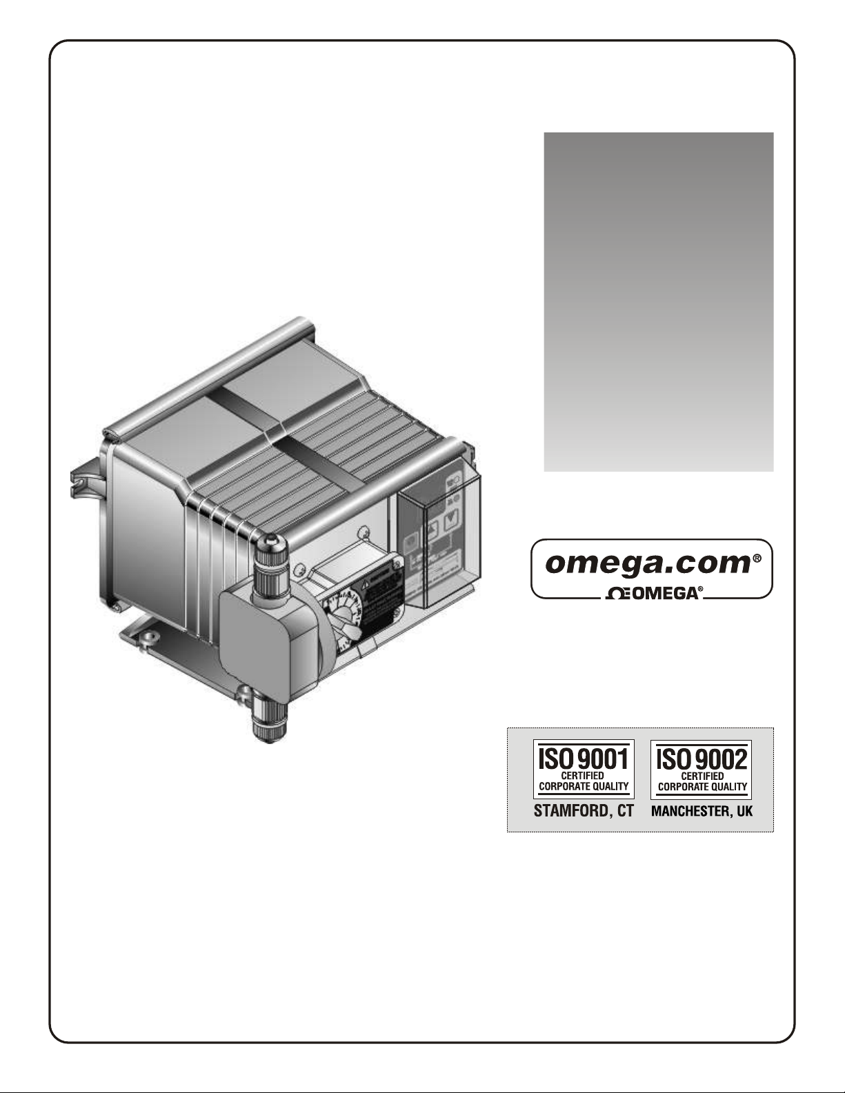
10 IN. (267 MM)
2
Page 4
10 IN. (254 MM)
VARIABLE SPEEDPUMP
FIELD
RUN
STANDBY
PRIME
RESETSERVICE
2- 4-20mA
1-MANUAL
Pumphead
Slide Clamps*
Adjustment knob
FIG. 3.0 PARTS LOCATOR DRAWING
* Slide both top & bottom clamps to the left only far enough to open the control
cover.
4.0 How To Install the Pump
CAUTION: PROPER EYE AND SKIN PROTECTION MUST BE WORN WHEN
INSTALLING AND SERVICING THE FPUDV1000
Note: All diagrams are strictly for guideline purposes only. Always consult an expert before
installing the pump into specialized systems.
The pump should be serviced by qualified persons only.
PROGRAM
INPUTMODES
RUN
PROGRAM
STAND-BY
PRIME
MINIMUM
MAXIMUM
DIGIT MODE
DISPLAY
3- 0-10VDC 4- PULSE (Hz)
J-Box
Control Cover
Motor Housing
Rear Cover
6
(159
1
4
IN.
MM)
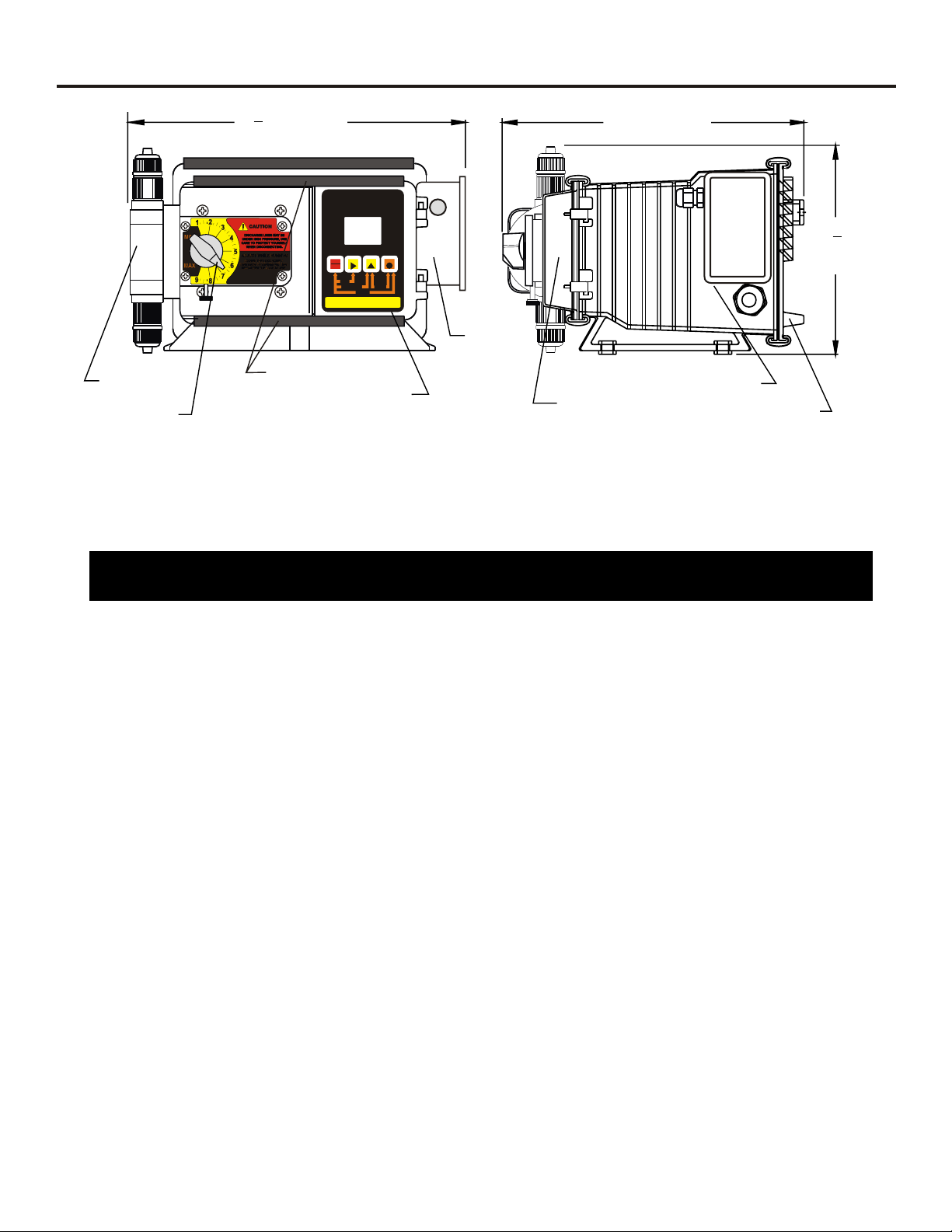
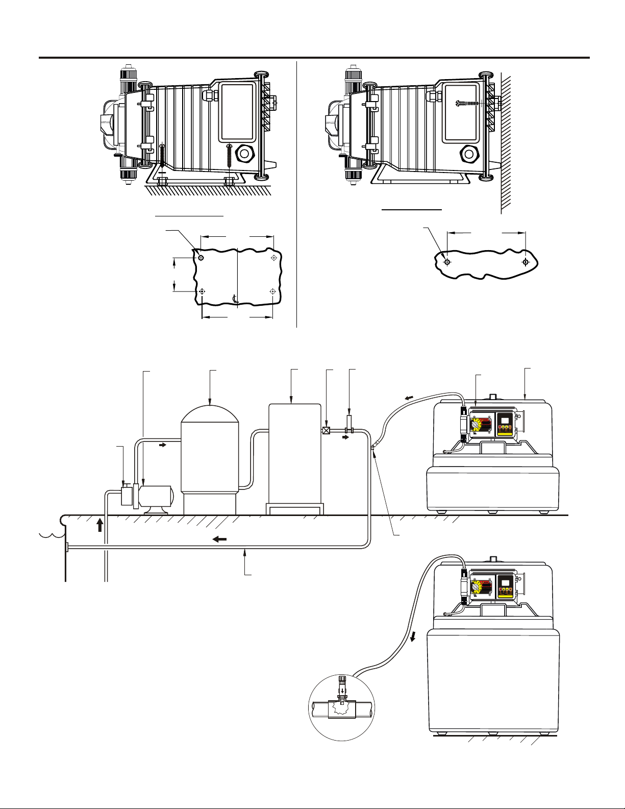
4.1 Mounting Location
Choose an area located near the chemical supply tank, chemical injection point and electrical
supply. Although the pump is designed to withstand outdoor conditions, a cool, dry, well
ventilated location is recommended. Install the pump where it can be easily serviced.
!
Mount the pump to a secure surface or wall using the enclosed hardware. Wall mount to a
solid surface only. Mounting to drywall with anchors is not recommended.
!
Keep the outlet (discharge) tubing as short as possible. Longer tubing increases the back
pressure at the pump tube.
!
Do not mount the pump directly over your chemical container. Chemical fumes may damage
the unit. Mount the pump off to the side or at a lower level than the chemical container.
!
Mounting the pump lower than the chemical container will gravity feed the chemical into the
pump. This “flooded suction” installation can reduce the time required to prime the pump.
Install a shut-off valve, pinch clamp or other means to halt the gravity feed to the pump during
servicing.
!
Your solution tank should be sturdy. Keep the tank covered to reduce fumes.
Page 6
1
2
3
5
4 6
9
10
Page 5
7
8
Drill .156 Dia. (5/32)
For Self-Tap Screw
#10 X 1” Phillips Steel
4 Places
Floor Mount
3-1/2”
FIG. 4.1 - INJECTOR MOUNTING
7-5/8”
7-3/8”
Wall Mount
Drill .156 Dia. (5/32)
For Self-Tap Screw
8-3/16”
#10 X 1” Phillips Steel
2 Places
Note: For wall-mounting, recommend drill & thread into
solid wood only.
7
VARIABLESPEEDPUMP
FIELD
RUN
STANDBY
PRIME
RESETSERVICE
INPUTMODES
2-4-20mA
1-MANUAL
RUN
PROGRAM
STAND-BY
PRIME
MINIMUM
MAXIMUM
DIGIT MODE
DISPLAY
PROGRAM
3-0-10VDC 4-PULSE(Hz)
lPoo
1. Strainer 7. Injector
2. Circulation Pump 8. Solution Tank
3. Filter 9. Injection Fitting (FPU1000-IF)
4. Heater 10. Return Line
5. Check Valve
6. Flowmeter
FIG. 4.2 - SWIMMING POOL INSTALLATION
¼" & ½" NPT Injector
FIG. 4.3 - TYPICAL INSTALLATION
Discharge
Tube
STANDBY
1-MANUAL
VARIABLESPEEDPUMP
RUN
PRIME
RESETSERVICE
RUN
PROGRAM
STAND-BY
PRIME
MINIMUM
MAXIMUM
DIGIT MODE
FIELD
DISPLAY
PROGRAM
INPUTMODES
3-0-10VDC 4-PULSE(Hz)
2-4-20mA
Page 7

4.2 Electrical Connections
4.2.1 Input Power Connections -
Be certain to connect the pump to the proper supply voltage. Using the incorrect voltage will
damage the pump and may result in injury. The voltage requirement is printed on the pump
serial label.
WARNING-RISK OF ELECTRICAL SHOCK
Jumper pins on the circuit board are factory preset for the correct voltage. See Fig. 4.4, page 7
for details.
The pump is supplied with a ground wire conductor and a grounding type attachment plug
(power cord). To reduce the risk of electric shock, be certain that the power cord is connected
only to a properly grounded, grounding type receptacle.
Note: When in doubt regarding your electrical installation, contact a licensed electrician.
Page 6
4.2.2 External Input Signal Connections -
The pump will accept any one of three different types of external input signals; 4-20 mA, 0-10
VDC, or frequency. Two types of frequency inputs, AC sine waves (magnetic coils type outputs) and Digital Square waves (Hall Effect signals, contact closures), are acceptable. A
jumper plug located on the circuit board is factory pre-set for AC sine wave signals, the jumper
must be re-positioned when digital square wave signals are being used. (See Fig. 4.4, page 7,
“Hz input jumper settings”)
All wiring connections are to be made inside of the junction box located on the side of the
pump. A liquid-tite connector is supplied and should be used for the external signal cable. The
signal input wires are color coded to the type of signal being used.
INPUT SIGNAL TYPE
4-20 mA
0-10 V DC
AC sine wave, Digital square wave
POSITIVE
WIRE COLOR
BLUE
ORANGE
WHITE
NEGATIVE
WIRE COLOR
BLACK
BLACK
BLACK
FIG. 4.3 WIRING CHART - INPUT SIGNAL WIRE COLORS
Page 8

Page 7
SIGNAL INPUT MODES / FUNCTIONS & WIRING COLOR CODES
INPUT MODE / FUNCTION
MANUAL
4-20 mA
0-10 VDC
FREQUENCY
ALARM RELAY
FLOW VERIFICATION SENSOR
(Digital square waves)
MOTOR ON SIGNAL
EXTERNAL INPUT CABLE
ACCEPTABLE CABLE JACKET RANGE:
RED (+20VDC)
BLACK (Ground)
BLUE (4-20 mA input)
ORANGE (0-10 VDC input)
WHITE (frequency input)
YELLOW (verification sensor input)
BROWN (motor-on contact output)
PURPLE X2 (alarm relay contacts)
.118 - .255 INCH
.( 3,0-6,5MM)
JUNCTION BOX
WIRES REQUIRED
NO CONNECTIONS
BLUE (+) & BLACK (-)
ORANGE (+) & BLACK (-)
WHITE (+) & BLACK (-)
PURPLE & PURPLE
RED (+ 20VDC) & BLACK (-) & YELLOW (signal)
BROWN (+) & BLACK (-)
(open - factory default)
AC LINE VOLTAGE SETTINGS
Hz INPUT JUMPER SETTINGS
Located under connector
AC sine waves
Jumper Not Installed
Digital square waves
Jumper Installed
INPUT SIGNAL CONNECTOR
7 wire bundle
LIQUID-TIGHT
CONNECTOR
ALARM OUTPUT
(CONTACT CLOSURE)
connect 2-conductor plug to either
normally open (NO) (factory default)
or normally closed (NC) side of receptacle.
1 AMP MAX @ 125VAC (24VDC)
RED (+)
DC
MOTOR
BLACK (-)
Ground (green)
MOTOR
RED (+)
MOTOR
BLACK (-)
NC
ON
AC LINE
NEUTRAL
110
220
110
One Jumper Installed
TS
ROBPE
.187 push tab connectors
1 AMP
250VAC
AC LINE
HOT
Common
Earth Ground (green)
230 VAC
on center position
(ends open)
Two Jumpers Installed
on end positions
(no open pins)
THERMAL SWITCH
2 conductors
PROTECTOR FUSE
1 Amp, 250 Volt AC
(Littlefuse #239001
or Equivalent)
Hot
AC
Input
Power
115 VAC
FIG. 4.4 WIRING DIAGRAM - CIRCUIT BOARD
Page 9

Page 8
4.3 How To Install the Tubing and Fittings
CAUTION: PROPER EYE AND SKIN PROTECTION MUST BE WORN WHEN
INSTALLING AND SERVICING THE FPUDV1000
4.3.1 Inlet Tubing - Locate the inlet fitting of the pump head, see fig 4.9. Remove the tube nut.
Push the clear PVC suction tubing onto the compression barb of the fitting. Use the tube nut to
secure the tube. Hand tighten only.
4.3.2 Footvalve/Strainer -Trim the inlet end of the suction tubing so that the strainer will rest
approximately one inche from the bottom of the solution tank. This will prevent sediment from
clogging the strainer. Slip the ceramic weight over the end of the suction tube. Press the
footvalve/strainer into the end of the tube. Secure the ceramic weight to the strainer. Drop the
strainer into the solution tank.
4.3.3 Outlet Tubing - Locate the outlet fitting of the pump head, see fig 4.9. Remove the tube nut.
Push the opaque outlet (discharge) tubing onto the compression barb of the fitting. Use the
tube nut to secure the tube. Hand tighten only.
Trim the other end of the outlet tube leaving only enough slack to connect it to the
Injection/Check valve Fitting (see below). Increasing the length of the outlet tube increases the
back pressure at the pump head, particularly when pumping viscous fluids.
Discharge Tube
(Rigid P.E.)
Tube Nut
Outlet Adapter
Pump Head
VARIABLE SPEED PUMP
FIELD
RUN
STANDBY
PRIME
RESETSERVICE
PROGRAM
INPUTMODES
2- 4-20mA
1-MANUAL
RUN
PROGRAM
STAND-BY
PRIME
MINIMUM
MAXIMUM
DIGIT MODE
DISPLAY
3- 0-10VDC 4- PULSE (Hz)
Suction Tubing
Ceramic
Weight
FootValve
Sub-Assembly
Footvalve Adapter
O-Ring
Ceramic Ball
O-Ring
Footvalve Body
Footvalve Strainer
Inlet Adapter
Tub e Nut
Suction Tubing
(clear PVC)
FootValve
FIG. 4.9
FIG. 4.10 FOOTVALVE ASSY.
Page 10

Page 9
4.3.4 Injection/Check Valve Fitting Installation - The Injection/Check valve fitting is designed to
install directly into either 1/4” or 1/2” female pipe threads. This fitting will require periodic
cleaning, especially when injecting fluids that calcify such as sodium hypochlorite. These lime
deposits and other build ups can clog the fitting increasing the back pressure and interfering
with the check valve operation. See section 6.0.
Install the Injection/Check valve directly into the piping system. Do not use a pipe stud with a
tee for insertion of the injection valve. The solution must inject directly into the flow stream.
Use Teflon thread sealing tape on the pipe threads. Push the opaque outlet (discharge) tubing
onto the compression barb of the Injection/Check valve fitting. Use the tube nut to secure the
tube. Hand tighten only.
EXPLODED VIEW
FIG. 4.11
TEE INSTALLATION
TEE INSTALLATION AND EXPLODED VIEW
INJECTION/CHECK VALVE
5.0 How To Operate The Pump
5.1 How to adjust the output- Cam-Type Mechanism Adjustment (fig. 5.1) - The flow
rate can be adjusted within a range of 5% -100% of maximum output (20:1 turndown ration) by
means of a mechanical, cam type mechanism. The mechanism adjusts the pump’s stroke
length to an infinite number of settings within the flow range. Because the pump’s output is
reduced by increasing the pressure of the system being injected into, the amount of suction lift,
and the viscosity of the fluid being injected, the pump must be over-sized to allow for these
factors. Sizing the pump to allow adjustment within the midrange is preferred to maintain
accuracy. Consult the factory for individual pump model output curve data.
To adjust the pump’s output:
1. With the pump running, loosen the lock screw.
2. Turn the adjustment knob to the desired setting.
3. Re-tighten the lock screw.
Adjustment Knob
(Cam Type Mechanism)
Lock screw
FIG. 5.1
Page 11

5.2 Description of Electronic Adjustment Controls -
Open the control panel door by sliding the upper and lower slide
clamps to the left. FIG. 5.2
!
RUN/STANDBY Button -
4
Press to start and stop the pump. The ARROW next to the
RUN will light when in the run mode. The ARROW next
word
to the word
4
Press to clear ALARM.
4
When pressed with the FIELD Button, initiates a 99 second
STAND-BY will blink when in the stand-by mode.
prime cycle which temporarily overrides the mode setting and
runs the pump motor at 100% speed. The ARROW next to
the word
4
When pressed with the DIGIT button, resets the 500 hour
PRIME will blink.
service warning timer to zero.
4
When pressed with the MODE button, initiates the programming mode. The ARROW next to the word
PROGRAM will
blink.
!
FIELD Button -
4
In the programming mode, selects the digit to be changed.
VARIABLE SPEED PUMP
1
VDC
mA Hz
SERVICE
DIGIT MODE
PROGRAM
3 - 0-10VDC 4 - PULSE (Hz)
RUN
STANDBY
1 - MANUAL
MODE
% SPEED
1000
ALARM
FIELD
PRIME
RESET SERVICE
INPUT MODES
2 - 4-20mA
Page 10
RUN
PROGRAM
STAND-BY
PRIME
MINIMUM
MAXIMUM
DISPLAY
!
DIGIT Button -
4
In the programming mode, increases the selected digit.
4
When pressed with the MODE Button, toggles the display
from % motor speed to input signal value.
!
MODE Button -
4
Used to select one of four operating modes.
Mode 1 - Manual Adjustment (external input disabled)
Mode 2 - 4-20mA input
Mode 3 - 0-10VDC input
Mode 4 - Frequency (Hz) input
SLIDE CLAMP
Slide both top & bottom
clamps to the left only far enough
(as shown) to open the control cover
Adjustment Knob
(Cam Type Mechanism)
RUN
STANDBY
1-MANUAL
VARIABLE SPEED PUMP
DIGIT MODE
FIELD
PRIME
DISPLAY
RESETSERVICE
PROGRAM
INPUTMODES
3- 0-10VDC 4 - PULSE (Hz)
2- 4-20mA
RUN
PROGRAM
STAND-BY
PRIME
MINIMUM
MAXIMUM
FIG. 5.1
Electronic Control Panel
FIG. 5.2
Page 12

Page 11
5.3 OPERATING MODE 1 - Output adjusted manually -
In this mode, the pump’s motor speed is adjusted manually using the front panel touch
pad. The motor speed can be adjusted from 0-100%. To adjust the speed:
4
Set the pump for mode 1. Press the MODE button until MODE 1 is shown on the
LCD display. The %SPEED icon will light. The large 3-DIGIT LCD will indicate the
currently programmed percentage of speed.
4
Enter the programming mode. At the same time, press the RUN/STANDBY button
and the MODE button. A blinking ARROW will point to the word PROGRAM indicating the program mode has been activated.
4
Press the FIELD button to select the digit to program. The digit will blink when
selected.
4
Press the DIGIT button to change the selected digit.
4
Repeat until all digits are programmed.
4
To exit the programming mode, press the RUN/STANDBY button and the MODE
button at the same time. The arrow next to the word PROGRAM will disappear.
[
NOTE: If while in the program mode no buttons are pressed within 20 seconds, the
circuitry will automatically return to the run mode, without saving changes.
[
5.4 -
OPERATING MODE 2 - Output adjusted by 4-20 mA input signal
In this mode, the pump’s motor speed is adjusted automatically based on the value of the
4-20 mA input signal. Any motor speed can be assigned to either the minimum or
maximum milliamp input values. However, the programmed minimum mA value must
be less than the programmed maximum mA value. The ALARM and SERVICE icons
will blink if the programming is in error. To assign the minimum and maximum motor
speed and the minimum and maximum mA input signal values:
4
Set the pump for mode 2. Press the MODE button until MODE 2 is shown on the
LCD display. The %SPEED or mA icon will light depending on the current display
setting. The large 3-DIGIT LCD will indicate the current motor speed or the current
mA input value.
4
Enter the programming mode. At the same time, press the RUN/STANDBY and
MODE buttons. A blinking ARROW will point to the word PROGRAM indicating the
program mode is activated. A blinking ARROW will point to the word MINIMUM
indicating the minimum value is ready to be programmed. The % SPEED icon will
blink indicating the percentage of speed is ready to be programmed.
4
Enter the motor speed at the minimum mA input signal value. Press the FIELD
button to select the digit to program. The digit will blink when selected.
4
Press the DIGIT button to change the selected digit.
4
Repeat until all digits are programmed.
4
Press the mode button. The % SPEED icon will stop blinking and the mA icon will
blink indicating the minimum mA value is ready to be programmed. The currently
programmed minimum value is shown on the 3-DIGIT LCD.
4
Enter the minimum mA input signal value. Note: this value must be less than the
maximum mA input signal value. Press the FIELD button to select the digit to program. The digit will blink when selected.
4
Press the DIGIT button to change the selected digit.
4
Repeat until all digits are programmed.
4
Press the mode button. The
Ma icon will stop blinking and the % SPEED icon will
blink. The ARROW next to the word MAXIMUM will blink indicating the maximum
value is ready to be programmed. The currently programmed maximum motor speed
value is shown on the 3-DIGIT LCD.
4
Enter the motor speed at the maximum mA input signal value. Press the FIELD
button to select the digit to program. The digit will blink when selected.
4
Press the DIGIT button to change the selected digit.
4
Repeat until all digits are programmed.
4
Press the mode button. The % SPEED icon will stop blinking and the mA icon will
blink indicating the maximum mA value is ready to be programmed. The currently
programmed maximum value is shown on the 3-DIGIT LCD.
4
Enter the maximum mA input signal value. Note: this value must be greater than
the minimum mA input signal value. Press the FIELD button to select the digit to
program. The digit will blink when selected..
4
Press the DIGIT button to change the selected digit.
4
Repeat until all digits are programmed.
RUN MODE 1
MODE
%SPEED
100
1
RUN
PROGRAM
STAND-BY
PRIME
MINIMUM
MAXIMUM
PROGRAM MODE 1
constant speed % setting
MODE
%SPEED
000
1
RUN
PROGRAM
STAND-BY
PRIME
MINIMUM
MAXIMUM
RUN MODE 2
MODE
2
mA
04.0
RUN
PROGRAM
STAND-BY
PRIME
MINIMUM
MAXIMUM
PROGRAM MODE 2
% speed at the minimum input
RUN
MODE
%SPEED
000
2
PROGRAM
STAND-BY
PRIME
MINIMUM
MAXIMUM
PROGRAM MODE 2
minimum input value
RUN
mA
2
PROGRAM
STAND-BY
PRIME
MINIMUM
MAXIMUM
MODE
04.0
Page 13

4
Press the mode button. The Ma icon will stop blinking and the %
SPEED icon will blink. The ARROW next to the word MAXIMUM will
blink indicating the maximum value is ready to be programmed. The
currently programmed maximum motor speed value is shown on the 3-
DIGIT LCD.
4
Enter the motor speed at the maximum mA input signal value.
Press the FIELD button to select the digit to program. The digit will
blink when selected.
4
Press the DIGIT button to change the selected digit.
4
Repeat until all digits are programmed.
4
Press the mode button. The % SPEED icon will stop blinking and the
mA icon will blink indicating the maximum mA value is ready to be
programmed. The currently programmed maximum value is shown on
the 3-DIGIT LCD.
4
Enter the maximum mA input signal value. Note: this value must be
greater than the minimum mA input signal value. Press the FIELD
button to select the digit to program. The digit will blink when selected..
4
Press the DIGIT button to change the selected digit.
4
Repeat until all digits are programmed.
4
Press the mode button. Programming is complete.
4
To exit the programming mode, press the RUN/STANDBY button and
the MODE button at the same time. The
PROGRAM arrow will disap-
pear.
Page 12
PROGRAM MODE 2
% speed at the maximum input
RUN
100
mA
2
PROGRAM
STAND-BY
PRIME
MINIMUM
MAXIMUM
RUN
2
PROGRAM
STAND-BY
PRIME
MINIMUM
MAXIMUM
MODE
% SPEED
PROGRAM MODE 2
maximum input value
MODE
20.0
Example 1
4 mA = 0% OUTPUT
20 mA = 100% OUTPUT
100
75
50
25
Pump Motor Speed (%)
0
6
8
4
Milliamp input (mA)
4 mA = 0% OUTPUT
20 mA = 75% OUTPUT
100
75
50
12
10
Example 3
MODE 2 PROGRAMMING EXAMPLES
Example 2
4 mA = 100% OUTPUT
20 mA = 0% OUTPUT
100
75
50
25
Pump Motor Speed (%)
0
6
8
14
16
18
20
4
Milliamp input (mA)
Example 4
4mA=20%OUTPUT
20 mA = 50% OUTPUT
100
75
50
10
12
14
16
18
20
Pump Motor Speed (%)
25
0
6
8
4
Milliamp input (mA)
10
12
14
16
18
20
Pump Motor Speed (%)
25
0
6
8
4
Milliamp input (mA)
10
12
14
16
18
20
Page 14

Page 13
5.5 - OPERATING MODE 3 - Output adjusted by 0-10VDC input signal
In this mode, the pump’s motor speed is adjusted automatically based on the
value of the 0-10VDC input signal. Any motor speed can be assigned to either
the minimum or maximum DC input signal values. However, the
programmed minimum VDC value must be less than the programmed
maximum VDC value. The ALARM and SERVICE icons will blink if the
programming is in error. To assign the minimum and maximum motor speed
and the minimum and maximum VDC input signal values:
4
Set the pump for mode 3. Press the MODE button until MODE 3 is
shown on the LCD display. The % SPEED or VDC icon will light depending on the current display setting. The large 3-DIGIT LCD will indicate the
current motor speed or the VDC input value.
4
Enter the programming mode. At the same time, press the
RUN/STANDBY and MODE buttons. A blinking ARROW will point to the
word PROGRAM indicating the program mode is activated. A blinking
ARROW will point to the word MINIMUM indicating the minimum value is
ready to be programmed. The % SPEED icon will blink indicating the
percentage of speed is ready to be programmed.
4
Enter the motor speed at the minimum VDC input signal value. Press
the FIELD button to select the digit to program. The digit will blink when
selected.
4
Press the DIGIT button to change the selected digit.
4
Repeat until all digits are programmed.
4
Press the mode button. The % SPEED icon will stop blinking and the VDC
icon will blink indicating the minimum VDC value is ready to be programmed. The currently programmed minimum value is shown on the 3-
DIGIT LCD.
4
Enter the minimum VDC input signal value. Note: this value must be
less than the maximum VDC input signal value. Press the FIELD button to
select the digit to program. The digit will blink when selected.
4
Press the DIGIT button to change the selected digit.
4
Repeat until all digits are programmed.
4
Press the mode button. The VDC icon will stop blinking and the % SPEED
icon will blink. The ARROW next to the word MAXIMUM will blink indicat-
ing the maximum value is ready to be programmed. The currently programmed maximum motor speed value is shown on the 3-DIGIT LCD.
4
Enter the motor speed at the maximum VDC input signal value. Press
the FIELD button to select the digit to program. The digit will blink when
selected.
4
Press the DIGIT button to change the selected digit.
4
Repeat until all digits are programmed.
4
Press the mode button. The % SPEED icon will stop blinking and the VDC
icon will blink indicating the maximum VDC value is ready to be programmed. The currently programmed maximum value is shown on the 3-
DIGIT LCD.
4
Enter the maximum VDC input signal value. Note: this value must be
greater than the minimum VDC input signal value. Press the FIELD button
to select the digit to program. The digit will blink when selected.
4
Press the DIGIT button to change the selected digit.
4
Repeat until all digits are programmed.
4
Press the mode button. Programming is complete.
4
To exit the programming mode, press the RUN/STANDBY button and the
MODE button at the same time. The PROGRAM arrow will disappear.
RUN MODE 3
MODE
3
VDC
00.0
PROGRAM MODE 3
% speed at the minimum input
MODE
%SPEED
000
PROGRAM MODE 3
minimum input value
MODE
VDC
00.0
PROGRAM MODE 3
% speed at the maximum input
MODE
%SPEED
100
PROGRAM MODE 3
maximum input value
MODE
VDC
10.0
RUN
PROGRAM
STAND-BY
PRIME
MINIMUM
MAXIMUM
RUN
3
PROGRAM
STAND-BY
PRIME
MINIMUM
MAXIMUM
RUN
3
PROGRAM
STAND-BY
PRIME
MINIMUM
MAXIMUM
RUN
3
PROGRAM
STAND-BY
PRIME
MINIMUM
MAXIMUM
RUN
3
PROGRAM
STAND-BY
PRIME
MINIMUM
MAXIMUM
Page 15

5.6 - OPERATING MODE 4 - Output adjusted by frequency (Hz) input signal
In this mode, the pump’s motor speed is adjusted automatically based on the
frequency (Hz) of the input signal. Any motor speed can be assigned to either
the minimum or maximum Hz input signals. However, the programmed
minimum Hz value must be less than the programmed maximum Hz
value. The ALARM and SERVICE icons will blink if the programming is in
error. To assign the minimum and maximum motor speed and the minimum
and maximum Hz input signal values:
4
Set the pump for mode 4. Press the MODE button until MODE 4 is
shown on the LCD display. The % SPEED or Hz icon will light depending
on the current display setting. The large 3-DIGIT LCD will indicate the
current motor speed or the Hz input value.
4
Enter the programming mode. At the same time, press the
RUN/STANDBY and MODE buttons. A blinking ARROW will point to the
word PROGRAM indicating the program mode is activated. A blinking
ARROW will point to the word MINIMUM indicating the minimum value is
ready to be programmed. The % SPEED icon will blink indicating the
percentage of speed is ready to be programmed.
4
Enter the motor speed at the minimum Hz input signal value. Press
the FIELD button to select the digit to program. The digit will blink when
selected.
4
Press the DIGIT button to change the selected digit.
4
Repeat until all digits are programmed.
4
Press the mode button. The % SPEED icon will stop blinking and the Hz
icon will blink indicating the minimum Hz value is ready to be programmed. The currently programmed minimum value is shown on the 3-
DIGIT LCD.
4
Enter the minimum Hz input signal value. Note: this value must be less
than the maximum Hz input signal value. Press the FIELD button to select
the digit to program. The digit will blink when selected.
4
Press the DIGIT button to change the selected digit.
4
Repeat until all digits are programmed.
4
Press the mode button. The Hz icon will stop blinking and the % SPEED
icon will blink. The ARROW next to the word MAXIMUM will blink indicat-
ing the maximum value is ready to be programmed. The currently programmed maximum motor speed value is shown on the 3-DIGIT LCD.
4
Enter the motor speed at the maximum VDC input signal value. Press
the FIELD button to select the digit to program. The digit will blink when
selected.
4
Press the DIGIT button to change the selected digit.
4
Repeat until all digits are programmed.
4
Press the mode button. The % SPEED icon will stop blinking and the Hz
icon will blink indicating the maximum Hz value is ready to be programmed. The currently programmed maximum value is shown on the 3-
DIGIT LCD.
4
Enter the maximum Hz input signal value. Note: this value must be
greater than the minimum Hz input signal value. Press the FIELD button
to select the digit to program. The digit will blink when selected.
4
Press the DIGIT button to change the selected digit.
4
Repeat until all digits are programmed.
4
Press the mode button. Programming is complete.
4
To exit the programming mode, press the RUN/STANDBY button and the
MODE button at the same time. The PROGRAM arrow will disappear.
Page 14
RUN MODE 4
MODE
4
000
PROGRAM MODE 4
% speed at the minimum input
MODE
% SPEED
000
PROGRAM MODE 4
minimum input value
MODE
000
PROGRAM MODE 4
% speed at the maximum input
MODE
% SPEED
82.5
PROGRAM MODE 4
minimum input value
MODE
628
RUN
PROGRAM
Hz
STAND-BY
PRIME
MINIMUM
MAXIMUM
RUN
4
PROGRAM
STAND-BY
PRIME
MINIMUM
MAXIMUM
RUN
4
PROGRAM
Hz
STAND-BY
PRIME
MINIMUM
MAXIMUM
RUN
4
PROGRAM
STAND-BY
PRIME
MINIMUM
MAXIMUM
RUN
4
PROGRAM
Hz
STAND-BY
PRIME
MINIMUM
MAXIMUM
Page 16

Page 15
Example 1
0 Hz = 0% OUTPUT
1000 Hz = 100% OUTPUT
100
MODE 4 PROGRAMMING EXAMPLES
Example 2
0 Hz = 100% OUTPUT
1000 Hz = 0% OUTPUT
100
Example 3
0 Hz = 10% OUTPUT
275Hz=75%OUTPUT
100
75
50
25
Pump Motor Speed (%)
0
0
Pump Motor Speed (%)
75
50
25
0
200
0
400
Frequency input (Hz)
600
800
1000
6.0 How to Maintain the Pump
CAUTION: PROPER EYE AND SKIN PROTECTION MUST BE WORN WHEN
INSTALLING AND SERVICING THE FPUDV1000
6.1 Routine Inspection and Maintenance
The pump requires very little maintenance. However, the pump and all accessories should be
checked regularly. This is especially important when pumping chemicals. Inspect all components for signs of leaking, swelling, cracking, discoloration or corrosion. Replace worn or damaged components immediately.
Cracking, crazing, discoloration and the like during the first week of operation are signs of
severe chemical attack. If this occurs, immediately remove the chemical from the pump.
Determine which parts are being attacked and replace them with parts that have been manufactured using more suitable materials. The manufacturer does not assume responsibility for
damage to the pump that has been caused by chemical attack.
600
200
400
Frequency input (Hz)
800
1000
Pump Motor Speed (%)
75
50
25
0
200
0
400
Frequency input (Hz)
600
800
1000
6.2 500 Hour Service Warning Timer
The pump is equipped with a service warning timer. After 500 hours of accumulated running
time, the SERVICE icon will light. This is a reminder that the pump should be inspected for
service. Your actual service period will depend on many factors such as the chemical used, back
pressure, temperature, viscosity, and motor RPM.
Simultaneously press the RUN/STANDBY and DIGIT buttons to reset the service timer to zero.
Note: Pressing the FIELD and DIGIT buttons will display the currently accumulated time value.
6.3 How to Clean the Pump
The pump will require occasional cleaning, especially the Injection fitting, the Footvalve/Strainer,
and the pump head valves. The frequency will depend on the type and severity of service.
]
Inspect and replace the pumphead valves as required.
]
When changing the diaphragm, the pump head chamber and pump head cover should be
wiped free of any dirt and debris.
]
Periodically clean the injection/check valve assembly, especially when injecting fluids that calcify
such as sodium hypochlorite. These lime deposits and other build ups can clog the fitting,
increase the back pressure and interfere with the check valve operation. See section 4.3.4. Fig.
4.11.
]
Periodically clean the suction strainer. Fig.4.10
]
Periodically inspect the air vents located under the motor housing and in the back on the rear
housing cover. Clean if necessary.
Page 17

age 1P6
epl c e a raw ngR a em nt P rts D i
36
61
06
14
62
67
86
42
40
39
38
35
37
56
36
52
51
43
59
55
32
66
64
53
65
45
75
52
31
z
E
H
(
D
E)
S
O
L
U
M
P
=
4
T
C
ID
ER
30
D
M
V
I
G
E
I
T
0
D
G
TE
0
O
=-1
R
3
M
S
A
WIN
A
RE
D
E
UT
F
E
I
P
L
2
L
-0m
N
C
EL
4
E
I
I
Y
E
B
=
C
U
F
M
T
C
I
E.
L 2
R
S
A
Y
P
9
U
B
9
D
AN
N
M
A
=
T
1
S
51
50
46
33
9
6
29
82
24
49
48
17
15
20
52
6
1
19
14
18
23
12
3
1
22
45
5
3
0
11
1
9
8
6
4
2
7
4444
1
Page 18

Page 17
Item Part No Description Qty
FPURV4 Inj. Valve .50-.25 Mpt X .37od, 6lb 1
66 76001-254 Junction Box, Ext. Input, Valox 1
67 90011-129 Screw, 6-32 X .25 Phil Pan SS Black 2
68 71000-133 Cover, J-Box with Gasket and Label 1
69 FPU1000-1F Inj. Valve .50-.25 Mpt X .37od, ½ lb 1
PARTS LIS T
Part No Description
34 C-618N-14 Gearbox, 14 RPM 1
Item
FPUDV 1000 SERIES
C-618N-30 Gearbox, 30 RPM 1
C-618N-45 Gearbox, 45 RPM 1
C-618N-60 Gearbox, 60 RPM 1
C-618N-125 Gearbox, 125 RPM 1
C-618N-250 Gearbox, 250 RPM 1
35 90011-078 Washer, Ground Screw, #8 Intrl/Star 1
36 90010-222 Lead Wire, ground, Green 1
37 90011-024 Ground Screw 8-32 x .25 Hex SL ST 1
38 90011-074 Washer, motor, #8 split-lock 2
39 90011-023 Screw, motor, 8-32 x .50 2
40 90010-244 Motor, 24V DC 1
70002-256 Gearmotor, 30 Rpm, 24 VDC 1
70002-257 Gearmotor, 45 Rpm, 24 VDC 1
70002-258 Gearmotor, 60 Rpm, 24 VDC 1
70002-259 Gearmotor, 125 Rpm, 24 VDC 1
70002-260 Gearmotor, 250 Rpm, 24 VDC 1
41 FPUD1000-BK Motor brush kit, (2 pc.) 24V DC 1
42 70002-255 Gearmotor, 14 Rpm, 24 VDC 1
44 90002-191 Door, Electronic Controls Cover 1
45 90006-579 Gasket, Enclosure Front, Neoprene 1
46 90012-245 Label Digital Timer w/ Ext. Input 1
47 76000-999 Slide Clamp, Enclosure Front 2
48 76001-000 Slide Clamp, Enclosure Rear 2
49 76001-253 Enclosure, Digital w/ Ext. Input 1
50 90003-559 Mounting Feet, Rubber 4
51 90011-091 Mounting Screw, #10 X 1.0” PhillipsSteel6
71000-176 Power Cord, 220v50hz, Digital Models 1
71000-177 Power Cord, 230v60hz, Digital Models 1
52 90011-094 Washer, Mounting, #10 Stainless 6
53 71000-175 Power Cord, 115v60hz, Digital Models 1
54 70000-589 Connector Liq-tite w/ nut .375 1
A-023N-V-230 Circuit board, 220V/230V 1
55 90010-235 Fuse, 1A, 250VAC 1
56 A-023N-V-115 Circuit board, 115V 1
57 90010-246 Wire set W/plug, alarm relay 1
59 90006-580 Gasket, Enclosure Back Plate,Neoprene1
60 90010-036 Wire Nut, Blue 2
61 76001-001 Tubing Spacer, Digital Circuit Board 2
62 71000-489 Enclosure Back Plate with Gasket, Valox1
63 90011-044 Screw 6-32 x .37 Swag Form 2
64 90007-515 Bushing, Junction Box Connector, Alum. 1
65 90008-199 Connector Liq-tite w/ nut .187 1
Part No Description
Item
1 C-345S Screen, FootValve, P.P. 1
2 90002-214 Body, FootValve, PVDF 1
2-108E O-ring Seat, FootValve, E.P. 1
3 2-108A O-ring Seat, FootValve, Aflas 1
90003-015 O-ring, FootValve, E.P. 1
4 C-385C Ball, FootValve, Ceramic 1
5 90003-014 O-ring, FootValve, Viton 1
FPUSV-V FootValve S/A, C-340V, Viton/Aflas 1
6 90002-215 Adapter, FootValve, PVDF 1
7 FPUSV-E FootValve S/A, C-340E, EP 1
8 C-346 Ceramic weight, C-346 1
9 C-334-6 Tubing Suction 3/8x5FT 1
C-560-6E Adapter S/A Bullet .37T EP 2
C-560-6S Adapter S/A Bullet .37T Silicon 2
10 C-330-6 Tube Nut, .37T, P.P. 2
11 C-560-6V Adapter S/A Bullet .37T Viton 2
12 FPUD1000-BCCartridge Bullet Valve S/A, Double-Ball 2
13 C-535 P/Head Noir Molded, P.P. 1
14 C-504HD Screw 10-32 x 1.25 4
C-535A6-6E Kit P/Head, HDN 37T E.P. P-P 1
15 C-535FW Cover P/Head, 1
16 C-535A6-6 Kit P/Head, HDN 37T Viton/Aflas, P-P 1
R-1505N Offset Cam #2 .055” 1
C-1505N-3 Offset Cam #3 .187” 1
C-1505N-4 Offset Cam #4 .100” 1
17 C-334-6-10 Tubing D/Charge, 3/8 x 10 FT 1
18 C-1505N Offset Cam #1 .125” 1
19 C-1514N Return Spring 2
20 C-1513N Stirrup with slide bearings 1
22 C-1502 Dial Knob 1
23 90011-168 Screw #6 x .62 PH oval ‘A’ 4
24 C-1519N Thumb Screw 6-32 x 1.125 1
R-1507A Drive Cam S/A #2 .055” 1
C-1507-3A Drive Cam S/A #3 .187” 1
C-1507-4A Drive Cam S/A #4 .100” 1
25 71000-363 Cover Cam S/A C-1100 1
28 C-1507A Drive Cam S/A #1 .125” 1
29 A-031 Spacer, Rotor 1
30 C-624N Screw 10-32 x .50 PHL PAN 4
31 90008-138 Plug .312 Hole Black 1
FPUD1000-15N Diaphragm S/A 2.015NEP/TFE 1
32 76001-183 Motor Mount, Large Diaphragm 1
33 C-406VT-15N Diaphragm S/A 2.0 15N, Viton/TFE 1
Page 19

USA
IN
MADE
RETURN REQUESTS / INQUIRIES
OMEGA warrants this unit to be free of defects in materials and workmanship and to give satisfactory
service for a period of from date of purchase. OMEGA Warranty adds an additional one
(1)month grace period to the normal one to cover handling and shipping time.
This ensures that OMEGA’s customers receive maximum coverage on each product. If the unit should
malfunction, it must be returned to the factory for evaluation. OMEGA’s Customer Service Department will
issue an Authorized Return (AR) number immediately upon phone or written request. Upon examination by
OMEGA, if the unit is found to be defective it will be repaired or replaced at no charge. However, this
WARRANTY is void if the unit shows evidence of having been tampered with or shows evidence of being
damaged as a result of excessive corrosion; or current, heat, moisture, or vibration; improper specification;
misapplication; misuse or other operating conditions outside of OMEGA’s control. Components which wear
or which are damaged by misuse are not warranted. These include contact points, fuses, and triacs.
Every precaution for accuracy has been taken in the preparation of this manual; however, OMEGA
ENGINEERING, INC. Neither assumes responsibility for any omissions or errors that may appear nor
assumes liability for any damages that result from the use of the products in accordance with the
information contained in this manual.
: Should this equipment be used in or with any nuclear installation or activity,
purchaser will indemnify OMEGA and hold OMEGA harmless from any liability or damage whatsoever
13 months
(1) year product warranty
OMEGA is glad to offer suggestions on the use of it’s various products. Nevertheless, OMEGA only
warrants that the parts manufactured by it will be as specified and free of defects.
OMEGA MAKES NO OTHER WARRANTIES OR REPRESENTATIONS OF ANY KIND WHATSOEVER,
EXPRESSED OR IMPLIED, EXCEPT THAT OF TITLE AND ALL IMPLIED WARRANTIES INCLUDING
ANY WARRANTY OF MERCHANTABILITY AND FITNESS
FOR A PARTICULAR PURPOSE ARE HEREBY DISCLAIMED.
LIMITATION OF LIABILITY: The remedies of purchaser set forth herein are exclusive and the total
liability of OMEGA with respect to this order, whether based on contract, warranty, negligence,
indemnification, strict liability or otherwise, shall not exceed the purchase price of the component
upon which liability is based. In no event shall OMEGA be liable for consequential, incidental or
special damages.
SPECIAL CONDITION
Direct all warranty and repair requests/inquiries to the OMEGA ENGINEERING Customer Service
Department. BEFORE RETURNING ANY PRODUCT(S) TO OMEGA, PURCHASER MUST OBTAIN AN
AUTHORIZED RETURN (AR) NUMBER FROM OMEGA’S CUSTOMER SERVICE DEPARTMENT (IN
ORDER TO AVOID PROCESSING DELAYS). The assigned AR number should then be marked on the
outside of the return package and on any correspondence.
OMEGA’s policy is to make running changes, not model changes, whenever an improvement is
possible. This affords our customers the latest in technology and engineering.OMEGA is a
registered trademark of OMEGA ENGINEERING, INC.©Copyright 1995 OMEGA ENGINEERING, INC.
All rights reserved. This documentation may not be copied, photocopied, reproduced, translated, or
reduced to any electronic medium or machine-readable form, in whole or in part, without written
consent of OMEGA ENGINEERING, INC.
OMEGA warrants this unit to be free of defects in materials and workmanship and to give satisfactory
service for a period of 13 months from date of purchase. OMEGA Warranty adds an additional one
(1)month grace period to the normal one (1) year product warranty to cover handling and shipping time.
This ensures that OMEGA’s customers receive maximum coverage on each product. If the unit should
malfunction, it must be returned to the factory for evaluation. OMEGA’s Customer Service Department will
issue an Authorized Return (AR) number immediately upon phone or written request. Upon examination by
OMEGA, if the unit is found to be defective it will be repaired or replaced at no charge. However, this
WARRANTY is void if the unit shows evidence of having been tampered with or shows evidence of being
damaged as a result of excessive corrosion; or current, heat, moisture, or vibration; improper specification;
misapplication; misuse or other operating conditions outside of OMEGA’s control. Components which wear
or which are damaged by misuse are not warranted. These include contact points, fuses, and triacs.
OMEGA is glad to offer suggestions on the use of it’s various products. Nevertheless, OMEGA only
warrants that the parts manufactured by it will be as specified and free of defects.
OMEGA MAKES NO OTHER WARRANTIES OR REPRESENTATIONS OF ANY KIND WHATSOEVER,
EXPRESSED OR IMPLIED, EXCEPT THAT OF TITLE AND ALL IMPLIED WARRANTIES INCLUDING
ANY WARRANTY OF MERCHANTABILITY AND FITNESS
FOR A PARTICULAR PURPOSE ARE HEREBY DISCLAIMED.
LIMITATION OF LIABILITY: The remedies of purchaser set forth herein are exclusive and the total
liability of OMEGA with respect to this order, whether based on contract, warranty, negligence,
indemnification, strict liability or otherwise, shall not exceed the purchase price of the component
upon which liability is based. In no event shall OMEGA be liable for consequential, incidental or
special damages.
WARRANTY/DISCLAIMER
Every precaution for accuracy has been taken in the preparation of this manual; however, OMEGA
ENGINEERING, INC. Neither assumes responsibility for any omissions or errors that may appear nor
assumes liability for any damages that result from the use of the products in accordance with the
information contained in this manual.
SPECIAL CONDITION: Should this equipment be used in or with any nuclear installation or activity,
purchaser will indemnify OMEGA and hold OMEGA harmless from any liability or damage whatsoever
Direct all warranty and repair requests/inquiries to the OMEGA ENGINEERING Customer Service
Department. BEFORE RETURNING ANY PRODUCT(S) TO OMEGA, PURCHASER MUST OBTAIN AN
AUTHORIZED RETURN (AR) NUMBER FROM OMEGA’S CUSTOMER SERVICE DEPARTMENT (IN
ORDER TO AVOID PROCESSING DELAYS). The assigned AR number should then be marked on the
outside of the return package and on any correspondence.
RETURN REQUESTS / INQUIRIES
FOR WARRANTY RETURNS, please have FOR NON WARRANTY REPAIRS OR
The following information available CALIBRATION, consult OMEGA for
1. P.O. Number under which the product current repair/calbration charges. Have
was PURCHASED. Information before contacting OMEGA.
2. Model and serial number of the product 1. P.O. Number to cover the COAST of
under warranty, and the repair/ calibration.
3. Repair Instructions and/or specific 2. Model and serial number of product,
Problems relative to the Product. and
3. Repair instructions and/or specific
Problems relative to the product
OMEGA’s policy is to make running changes, not model changes, whenever an improvement is
possible. This affords our customers the latest in technology and engineering.OMEGA is a
registered trademark of OMEGA ENGINEERING, INC.©Copyright 1995 OMEGA ENGINEERING, INC.
All rights reserved. This documentation may not be copied, photocopied, reproduced, translated, or
reduced to any electronic medium or machine-readable form, in whole or in part, without written
consent of OMEGA ENGINEERING, INC.
Page 20

Where Do I Find Everything I Need For
Process Measurement and Control?
OMEGA... Of Course!
Shop on line at www.Omega.com
TEMPERATURE
Thermocouple, RTD & Thermistor Probes, Connectors, Panels & Assemblies
Wire: Thermocouple, RTD & Thermistor
Calibrations & Ice Point References
Recorders, Controllers & Process Monitors
Infrared Pyrometers
PRESSURE / STRAIN FORCE
Transducers & Strain Gauges
Load Cells & Pressure Gauge
Displacement Transducers
Instrumentation & Accessories
FLOW / LEVEL
Rotameters, Gas Mass Flowmeters & Flow Computers
Air Velocity Indicators
Turbine / Paddlewheel Systems
Totalizers & Batch Controllers
pH / CONDUCTIVITY
pH Electrodes,Testers& Accessories
Benchtop / Laboratory Meters
Controllers, Calibrators, Simulators & Pumps
Industrial pH & Conductivity Equipment
DATA ACQUISITION
Thermocouple, RTD & Thermistor Probes, Connectors, Panels & Assemblies
Wire: Thermocouple, RTD & Thermistor
Calibrations & Ice Point References
Recorders, Controllers & Process Monitors
Infrared Pyrometers
HEATERS
Heating Cable
Cartridge & Strip Heaters
Immersion & Band Heaters
Flexible Heaters
Laboratory Heaters
ENVIRONMENTAL MONITORING AND CONTROL
Metering & Control Instrumentation
Refractometers
Pumps & Tubing
Air, Soil & Water Monitors
Industrial Water & Wastewater Treatment
pH, Conductivity & Dissolved Oxygen Instruments
M-4197/0505
 Loading...