

Page 1
User’s Guide
Shop online at
Omega.com
e-mail: info@omega.com
For latest product manuals:
Omegamanual.info
DIAPHRAGM INJECTOR
MODEL FPUDT600
Operating Manual
Page 2

OMEGAnet Online Service Internet e-mail
Omega.com info@omega.com
Servicing North America:
U.S.A.: One Omega Drive, P.O. Box 4047
ISO 9001 Certified Stamford, CT 06907-0047
TEL: (203) 359-1660 FAX: (203) 359-7700
E-mail: info@omega.com
Canada: 976 Bergar
Laval (Quebec) H7L5A1, Canada
TEL: (514) 856-6928 FAX: (514) 856-6886
E-mail: info@omega.ca
For immediate technical or application assistance:
U.S.A. And Canada: Sales Service: 1-800-826-6342 / 1-800-TC-OMEGA
Customer Service: 1-800-622-2378 / 1-800-622-BEST
Engineering Service: 1-800-872-9436 / 1-800-USA-WHEN
Mexico: En Espanol: (001) 203-359-7803 e-mail: espanol@omega.com
FAX: (001) 203-359-7807 info@omega.com.mx
Service Europe:
Benelux: Postbus 8034, 1180 LA Amstelveen, The Netherlands
TEL: +31 (0)20 3472121 FAX: +31 (0)20 6434643
Toll Free in Benelux: 0800 0993344
E-mail: sales@omega.fr
Czech Republic: Frystatska 184, 733 01 Karvina, Czech Republic
Tel: +420 (0)59 6311899 FAX: +420 (0)59 6311114
Toll Free: 0800-1-66342 e-mail: info@omegashop.cz
France: 11, rue Jacques Cartier, 78280 Guyancourt, France
TEL: +33 (0)1 61 37 2900 FAX: +33 (0)1 30 57 5427
Toll Free in France: 0800 466 342
E-mail: sales@omega.fr
Germany/Austria: Daimlerstrasse 26, D-75392 Deckenpfronn, Germany
TEL: +49 (0)7056 9398-0 FAX: +49 (0)7056 9398-29
Toll Free in Germany: 0800 639 7678
E-mail: info@omega.de
United Kingdom: One Omega Drive, River Bend Technology Centre
ISO 9002 Certified Northbank, Irlam, Manchester
M44 5BD United Kingdom
TEL: +44 (0)161 777 6611 FAX: +44 (0)161 777 6622
Toll Free in United Kingdom: 0800-488-488
E-mail: sales@omega.uk
It is the policy of OMEGA Engineering, Inc. To comply with all worldwide safety and EMC/EMI regulations that apply. OMEGA is constantly pursuing
certification of its products to the European New Approach Directives. OMEGA will add the CE mark to every appropriate device upon certification.
The information contained in this document is belived to be correct, but OMEGA accepts no liability for any erroes it contains, and reserves the right to alter specifications
without notice. WARNING: These products are not designed for usein, and should not be used for, human applications.
Page 3

FPUDT600
TABLE OF CONTENTS
SECTION HEADING PAGE
1 Introduction 2
2 Specifications 2
3 FPUDT600 Features 3
4 How to install the FPUDT600 3
4.1 Mounting location 3
4.2 Electrical connections 5
4.3 How to install the tubing and fittings 6
5 How to operate the FPUDT600 8
5.1 Adjusting the Pump Output - Standard Models 8
5.2 Adjusting the Pump Output - Fixed cycle timer Models 8
5.3 Measuring the pump’s output - volumetric test 9
6 How to maintain the FPUDT600 9
Page 2
6.1 Routine inspection and cleaning 9
6.2 How to clean the FPUDT600 9
1.0 Introduction
Thank you for purchasing the FPUDT600 positive displacement metering pump. The FPUDT600 is
designed to inject chemicals into piping systems. All models are equipped with a top mounted mechanical flow rate adjustment knob. Optional on/off cycling timers are available.
2.0 Specifications
Maximum Working Pressure 125 psig / 8.6 bar*
Maximum Fluid Temperature 130 F / 54 C
Output Accuracy +/- 10% of maximum (water @ 70 F, 0 psig, and 5’ suction lift)
Ambient Temperature Range 14 to 110 F / -10 to 43 C
Enclosure Zinc - Metal
Duty Cycle Continuous
Maximum Viscosity 1,000 Centipoise
Maximum Suction Lift up to 10 ft. water
Power Requirements 115V60Hz 45 Watts
Dimensions 6-1/2” high x 6-1/2” wide x 5-3/4” deep
Weight 8 lb.
o o
o
o o
220V50Hz 45 Watts
230V60Hz 45 Watts
24V60Hz 45 Watts
Page 4

Page 3
3.0 FPUDT600 Features
!
Double-ball ceramic check valves.
!
PVDF (Kynar) valve assemblies.
!
Viton o-rings.
!
High outlet pressure capability of 125 PSIG.*
!
Easy access, side mounted mechanical feed rate adjustment.
!
Ball bearing supported motor drive shaft.
!
Permanently lubricated ball bearing motor.
!
27:1 adjustment turn down ratio.
!
Easy servicing.
!
Includes suction tube foot valve & strainer, suction tube weight, suction tubing, discharge tubing and
injection fitting with internal back-flow check valve and mounting hardware.
* Most models.
4.0 How To Install the FPUDT600
Become familiar with the parts shown
Junction box
Pump
head
FPUDT600
Top valve
fitting
Output
adjustment
(cam cover not shown)
Bottom valve
fitting
CAUTION: PROPER EYE AND SKIN PROTECTION MUST BE WORN
WHEN INSTALLING AND SERVICING THE FPUDT600
Note: All diagrams are strictly for guideline purposes only. Always consult an expert before installing
the FPUDT600 into specialized systems.
The FPUDT600 should be serviced by qualified persons only.
4.1 Mounting Location
Choose an area located near the chemical supply tank, chemical injection point and electrical supply.
Install the pump where it can be easily serviced.
!
Mount the pump to a secure surface or wall using the enclosed hardware. Wall mount to a solid surface
only. Mounting to drywall with anchors is not recommended.
!
Keep the outlet (discharge) tubing as short as possible. Longer tubing increases the back pressure at the
pump head.
!
Do not mount the pump directly over your chemical container. Chemical fumes may damage the unit.
Mount the pump off to the side or at a lower level than the chemical container.
!
Mounting the pump lower than the chemical container will gravity feed the chemical into the pump. This
“flooded suction” installation can reduce the time required to prime the pump. Install a shut-off valve,
pinch clamp or other means to halt the gravity feed to the pump during servicing.
!
Your solution tank should be sturdy. Keep the tank covered to reduce fumes.
!
Be sure your installation does not constitute a cross connection with the drinking water supply. Check
your local plumbing codes.
Page 5
FPUDT600
Page 4
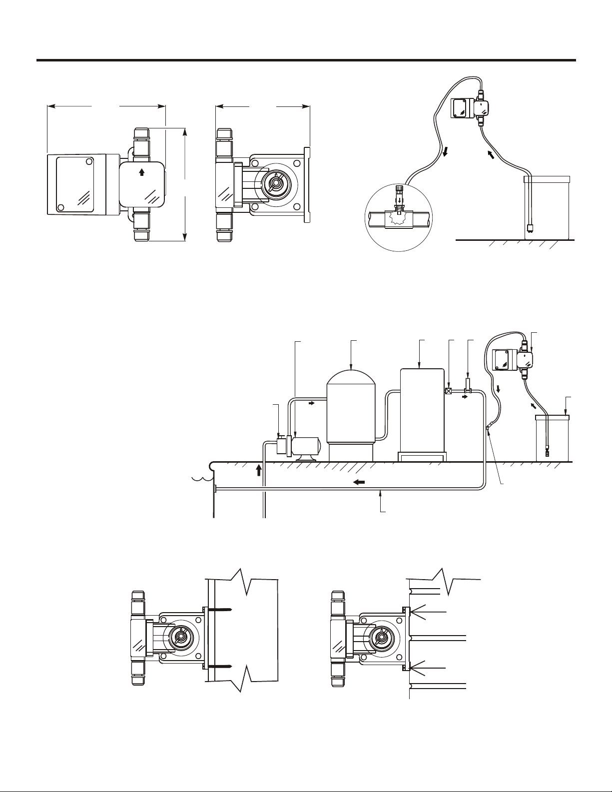
6-3/4”
171.5mm
6-1/4”
158.8mm
5-5/16”
134.9mm
FIG. 4.1 DIMENSIONAL DRAWING
1. Strainer
2. Circulation Pump
3. Filter
4. Heater
5. Check Valve
6. Flowmeter
7. Injector
FPUDT600
8. Solution Tank
9. Injection Fitting
10. Return Line
l
o
oP
FPUDT600
Pumping unit
Discharge
Tube
55
44
33
22
11
00
Chemical
Container
¼
" "
& ½
Suction Tube
(vertical)
N
P
T
I
n e r
j c
to
FIG. 4.2 TYPICAL INSTALLATION
7
5
3
2
2
11
3
1010
5
4
4
6
6
9
9
7
8
8
FIG. 4.3 SWIMMING POOL INSTALLATION
Stud
55
44
33
22
11
00
Stud Mount
55
44
33
22
11
00
Masonry
FIG. 4.4 WALL MOUNTING
Page 6

Page 5
4.2 Electrical Connections
4.2.1 Input Power Connections
Be certain to connect the pump to the proper supply voltage. Using the incorrect voltage will damage
the pump and may result in injury. The voltage requirement is printed on the pump serial label.
Note: When in doubt regarding your electrical installation, contact a licensed electrician.
The FPUDT600 is supplied with a junction box for field wiring.
JUNCTION BOX MODELS -To reduce the risk of electric shock, be certain that a grounding
conductor is connected to the green grounding screw located in the junction box.
FPUDT600
MOTOR LEADWIRES
INPUT
VOLTAGE
115V 60Hz
220V 50Hz
230V 60Hz
BLACK or YELLOW
BLUE or YELLOW
BLACK or YELLOW
24V 60Hz
* Yellow leadwire : thermally protected motor
Black or Blue leadwire: standard impedance protected motor
Hot
AC
Input
Power
Common
Earth Ground (green)
HOT
LEADWIRE
BLUE
NEUTRAL
LEADWIRE
*
*
*
*
BLUE
BROWN
RED
WHITE
Hot
Neutral
Ground (green)
GROUND
LEADWIRE
GREEN
GREEN
GREEN
GREEN
AC
MOTOR
FIG. 4.5 WIRING DIAGRAM - STANDARD MODELS
Page 7

FPUDT600
Common
Hot
Earth Ground (green)
Power
Cord
Page 6
Cycle Adjustment
Potentiometer
120VAC
220/230 VAC
HOT
LOAD
Timer
Board
AC
MOTOR
Neutral
Hot
FIG. 4.6 WIRING DIAGRAM - FPUDT600 -T MODELS
4.3 How To Install the Tubing and Fittings
CAUTION: PROPER EYE AND SKIN PROTECTION MUST BE WORN
WHEN INSTALLING AND SERVICING THE FPUDT600
4.3.1 Inlet Tubing - Locate the inlet fitting of the pump head, see fig 4.7. Remove the tube nut. Push the
clear PVC suction tubing onto the compression barb of the fitting. Use the tube nut to secure the tube.
Hand tighten only.
4.3.2 Footvalve/Strainer -Trim the inlet end of the suction tubing so that the strainer will rest in a vertical
position, approximately one inch from the bottom of the solution tank. This will prevent sediment from
clogging the strainer. Loss of prime may occur if the footvalve is permitted to lay on the bottom of the
solution tank in a horizontal position. Slip the ceramic weight over the end of the suction tube. Press
the footvalve/strainer into the end of the tube. Secure the ceramic weight to the strainer. Drop the
strainer into the solution tank.
4.3.3 Outlet Tubing - Locate the outlet fitting of the pump head, see fig 4.7. Remove the tube nut. Push the
rigid outlet (discharge) tubing onto the compression barb of the fitting. Use the tube nut to secure the
tube. Hand tighten only.
Trim the other end of the outlet tube leaving only enough slack to connect it to the Injection/Check valve
Fitting (FIG. 4.9). Increasing the length of the outlet tube increases the back pressure at the pump head,
particularly when pumping viscous fluids.
Keep the inlet and outlet tubes as short as possible.
Page 8

Page 7
Discharge Tube
(Opaque P.E.)
Tube Nut
FPUDT600
Footvalve Adapter
Suction Tubing
FIG. 4.7
Outlet Adapter
Pump Head
Inlet Adapter
Tube Nut
Suction Tubing
(clear PVC)
FootValve
Ceramic
Weight
FootValve Assembly
Must be installed in
a vertical position.
DO NOT LAY ON SIDE!
FIG. 4.8 FOOTVALVE ASSY.
O-Ring
Ceramic Ball
O-Ring
Footvalve Body
Footvalve Strainer
4.3.4 Injection/Check Valve Fitting Installation - The Injection/Check valve fitting is designed to install
directly into either 1/4” or ½” female pipe threads. This fitting will require periodic cleaning, especially
when injecting fluids that calcify such as sodium hypochlorite. These lime deposits and other build ups
can clog the fitting increasing the back pressure and interfering with the check valve operation. See
section 6.0.
Install the Injection/Check valve directly into the tee fitting. Do not install the fitting into a pipe stud
and then into the tee. The solution must inject directly into the flow stream.
Use Teflon thread sealing tape on the pipe threads. Push the opaque outlet (discharge) tubing onto the
compression barb of the Injection/Check valve fitting. Use the tube nut to secure the tube. Hand tighten
only.
FIG. 4.9
INJECTION/CHECK VALVE
TEE INSTALLATION AND EXPLODED VIEW
Page 9

Page 8
5.0 How To Operate The FPUDT600
5.1 Adjusting the Pump Output
The FPUDT600 flow rate can be adjusted within a range of approximately 10%-100% of maximum output (27:1
turndown ratio) by means of a mechanical, cam type mechanism. The mechanism adjusts the pump’s stroke length to 1 of
27 settings within the flow range. The pump’s output is affected by the pressure of the system , the amount of suction lift,
and the viscosity of the fluid being injected into the pump must be over-sized to allow for these factors. Sizing the pump
to allow adjustment within the midrange is preferred to maintain accuracy. Consult the factory for individual pump model
output curve data.
To adjust the pump output:
1. Make sure the pump is off before adjusting.
2. Loosen the wing nut.
3. Turn adjusting knob so the pointer is on the desired setting. Note: pump less chemical at first, then re-adjust.
4. While holding the knob, tighten the wing nut to keep the knob at the desired setting. Note: wing nut must be tight.
Adjustment Knob
66
55
44
33
22
11
00
Wing Nut
FIG. 5.1 Adjustment Cam
5.2 Priming The Pump
Each pump is factory tested with water. The test water is sealed in the pump head keeping the valves wet to aid in
priming. If the valves have dried or priming is difficult due to back pressure, do the following:
1. Remove the opaque discharge tubing from the top valve fitting in the pumphead.
2. Remove the top and bottom valve fittings and immerse in water to wet the valves. Reinstall the fittings.
3. With the discharge tubing removed, start the pump. Stop the pump when the fluid enters the pumphead.
4. Attach the discharge tubing to the top valve fitting.
5. Be sure the footvalve/strainer is attached to the suction tubing and is installed in a vertical position.
If your installation is at high altitude, priming may be more difficult since the atmospheric pressure is decreased. When
the suction line is dry, the diaphragm may not create enough pull. If this is the case, do the following:
1. Remove the clear suction tube from the bottom valve fitting and fill completely with water.
2. While the pump is running, attach the tube (filled with water) to the bottom valve fitting.
3. When the fluid enters the pumphead, place the foot valve in the solution tank.
4. Be sure the footvalve/strainer is attached to the suction tubing and is installed in a vertical position.
Page 10

Page 9
5.3 Measuring the Pump’s Output - Volumetric Test.
This volumetric test will take into account individual installation factors such as line pressure, fluid
viscosity, suction lift, etc. This test is the most accurate for measuring the injector’s output in an individual installation.
1. Be sure the Injection Fitting and Footvalve/Strainer is clean and working properly.
2. With the injector installed under normal operating conditions, place the Footvalve/Strainer in a large
graduated cylinder.
3. Fill the graduated cylinder with the solution to be injected and run the injector until all air is removed
from the suction line and the solution enters the discharge tubing.
4. Refill the graduated cylinder, if necessary, and with the Footvalve completely submerged in the
solution, note the amount of solution in the graduated cylinder.
5. Run the injector for a measured amount of time and note the amount of fluid injected. A longer testing
time will produce more accurate results.
5.4 Timer Equipped Model
1.The pause control knob adjusts the cycle timer’s time on. The FPUDT600 standard cycle time is set at
one minute. (+-10%) Other cycle lengths are available.
2. To adjust the amount of time on,turn the pause control knob to the correct setting. ½ equals
approximately 30 seconds on. 3/4 equals approximately 45seconds on, etc.
FPUDT600
6.0 How to Maintain the FPUDT600
6.1 Routine Inspection and Maintenance
The FPUDT600 requires very little maintenance. However, the pump and all accessories should be
checked regularly. This is especially important when pumping chemicals. Inspect all components for
signs of leaking, swelling, cracking, discoloration or corrosion. Replace worn or damaged components
immediately.
Cracking, crazing, discoloration and the like during the first week of operation are signs of severe
chemical attack. If this occurs, immediately remove the chemical from the pump. Determine which
parts are being attacked and replace them with parts that have been manufactured using more suitable
materials. The manufacturer does not assume responsibility for damage to the pump that has been
caused by chemical attack.
6.2 How to Clean the FPUDT600
The FPUDT600 will require occasional cleaning, especially the Injection fitting, the Footvalve/Strainer,
and the pump head valves. The frequency will depend on the type and severity of service.
When changing the diaphragm, the pump head chamber should be wiped free of any dirt and debris.
]
Periodically clean the injection/check valve assembly. Dirt and other build ups can clog the fitting,
increase the back pressure and interfere with the check valve operation. See section 4.3.4. FIG. 4.9.
]
Periodically clean the suction strainer. FIG. 4.8.
]
Periodically inspect the air vents located on the back of the motor compartment. Clean if necessary.
Page 11

FPUDT600
Page 10
FPUDT600
11
27
12
Optional
Exploded View
1
25
13
14
15
26
16
28
4
15
2
3
17
18
19
20
T.I. Anti siphon valve
fitting
Threaded Anti siphon
valve, ¼ & ½” N.P.T.
22
8
9
10
21
23
4
24
3
25
5
6
7
Page 12

Page 11
FPUDT600 Parts List
Catalog No. Description Amount Reqd.
1. C-395-6V Injection / anti-syphon valve 6 PSI, Viton® 1
C-395-6E Injection / anti-syphon valve 6 PSI, EP (optional) 1
2. C-335-6 Discharge Tubing 3/8 OD, 5ft. Opaque Poly-E 1
3. C-330-6 Tube nut 2
4. K-568V-4 Bullet valve (double ball), Viton®, 4 pack set 2
K-568V-10 Bullet valve (double ball), Viton®, 10 pack set 2
K-569E-4 Bullet valve (double ball), EP, 4 pack set (optional) 2
K-569E-10 Bullet valve (double ball), EP, 10 pack set (optional) 2
5. C-334-6 Suction tubing 3/8” OD, 5ft. Clear PVC w/ indicator 1
6. C-346 Ceramic weight 1
7. C-345V Foot valve / strainer Poly-Pro, Viton® 1
C-345E Foot valve / strainer Poly-Pro, EP (optional) 1
8. C-535 Heavy duty molded pump head 1
9. C-504HD Screw, HD Pump head 10-32 X 1-1/4” 4
10. C-535FC Pump head cover, Chem-Feed logo 1
11. C-628 Cover Screw 6-32 X 2-3/4” Steel 2
12. C-608P Motor Cover 1
13. C-625 Motor screw 8-32 X 2-1/2” 2
14. C-612F Rotor Fan 1
15. C-612PB Rotor Bearing 2
16. C-616PN Rotor w/ Spacers 1
17. C-618P-14 Gearbox Assembly, 14 RPM 1
C-618P-30 Gearbox Assembly, 30 RPM 1
C-618P-45 Gearbox Assembly, 45 RPM 1
C-618P-60 Gearbox Assembly, 60 RPM 1
C-618P-125 Gearbox Assembly, 125 RPM 1
C-618P-250 Gearbox Assembly, 250 RPM 1
18. C-301 Motor Mount 1
19. C-624 Motor Mount Screw 10-32 X ½ ” 4
20. C-325 Cam S/A FPUDT600 1
21. C-304 Yoke w/ Bearing 1
22. C-406T Diaphragm Teflon coated, EP 1
23. 90011-155 Screw 6-32 X 3/8” 1
24. 90002-201 Cam Cover 1
25. C-560-6V Bullet Valve Adapter, Viton® O-ring 2
C-560-6E Bullet Valve Adapter, EP O-ring 2
26. 90007-515 ½” Aluminum Chase Nipple 1
27. C-308J Junction Box Complete w/Cover and Gasket 1
28. C-615P-1 Stator S/A 115V / 60Hz, blue-black (lead wires) 1
C-615P-2 Stator S/A 230V / 60Hz, red-black (lead wires) 1
C-615P-3 Stator S/A 220V / 50Hz, brown-blue (lead wires) 1
C-615P-4 Stator S/A 24V / 60Hz, blue-white (lead wires) 1
C-615P-6 Stator S/A 230V / 60Hz, red-yellow (lead wires) 1
C-615P-8 Stator S/A 220V / 50Hz, brown-yellow (lead wires) 1
C-615P-9 Stator S/A 115V / 60Hz, blue-yellow (lead wires) 1
FPUDT600
RETURN REQUESTS / INQUIRIES RETURN REQUESTS / INQUIRIES
Page 13

MADEMADE
ININ
USAUSA
OMEGA warrants this unit to be free of defects in materials and workmanship and to give satisfactory
OMEGA warrants this unit to be free of defects in materials and workmanship and to give satisfactory
service for a period of from date of purchase. OMEGA Warranty adds an additional one
service for a period of 13 months from date of purchase. OMEGA Warranty adds an additional one
(1)month grace period to the normal one to cover handling and shipping time.
(1)month grace period to the normal one (1) year product warranty to cover handling and shipping time.
This ensures that OMEGA’s customers receive maximum coverage on each product. If the unit should
This ensures that OMEGA’s customers receive maximum coverage on each product. If the unit should
malfunction, it must be returned to the factory for evaluation. OMEGA’s Customer Service Department will
malfunction, it must be returned to the factory for evaluation. OMEGA’s Customer Service Department will
issue an Authorized Return (AR) number immediately upon phone or written request. Upon examination by
issue an Authorized Return (AR) number immediately upon phone or written request. Upon examination by
OMEGA, if the unit is found to be defective it will be repaired or replaced at no charge. However, this
OMEGA, if the unit is found to be defective it will be repaired or replaced at no charge. However, this
WARRANTY is void if the unit shows evidence of having been tampered with or shows evidence of being
WARRANTY is void if the unit shows evidence of having been tampered with or shows evidence of being
damaged as a result of excessive corrosion; or current, heat, moisture, or vibration; improper specification;
damaged as a result of excessive corrosion; or current, heat, moisture, or vibration; improper specification;
misapplication; misuse or other operating conditions outside of OMEGA’s control. Components which wear
misapplication; misuse or other operating conditions outside of OMEGA’s control. Components which wear
or which are damaged by misuse are not warranted. These include contact points, fuses, and triacs.
or which are damaged by misuse are not warranted. These include contact points, fuses, and triacs.
OMEGA is glad to offer suggestions on the use of it’s various products. Nevertheless, OMEGA only
OMEGA is glad to offer suggestions on the use of it’s various products. Nevertheless, OMEGA only
warrants that the parts manufactured by it will be as specified and free of defects.
warrants that the parts manufactured by it will be as specified and free of defects.
OMEGA MAKES NO OTHER WARRANTIES OR REPRESENTATIONS OF ANY KIND WHATSOEVER,
OMEGA MAKES NO OTHER WARRANTIES OR REPRESENTATIONS OF ANY KIND WHATSOEVER,
EXPRESSED OR IMPLIED, EXCEPT THAT OF TITLE AND ALL IMPLIED WARRANTIES INCLUDING
EXPRESSED OR IMPLIED, EXCEPT THAT OF TITLE AND ALL IMPLIED WARRANTIES INCLUDING
ANY WARRANTY OF MERCHANTABILITY AND FITNESS
ANY WARRANTY OF MERCHANTABILITY AND FITNESS
FOR A PARTICULAR PURPOSE ARE HEREBY DISCLAIMED.
FOR A PARTICULAR PURPOSE ARE HEREBY DISCLAIMED.
LIMITATION OF LIABILITY: The remedies of purchaser set forth herein are exclusive and the total
LIMITATION OF LIABILITY: The remedies of purchaser set forth herein are exclusive and the total
liability of OMEGA with respect to this order, whether based on contract, warranty, negligence,
liability of OMEGA with respect to this order, whether based on contract, warranty, negligence,
indemnification, strict liability or otherwise, shall not exceed the purchase price of the component
indemnification, strict liability or otherwise, shall not exceed the purchase price of the component
upon which liability is based. In no event shall OMEGA be liable for consequential, incidental or
upon which liability is based. In no event shall OMEGA be liable for consequential, incidental or
special damages.
special damages.
13 months
WARRANTY/DISCLAIMER
(1) year product warranty
Every precaution for accuracy has been taken in the preparation of this manual; however, OMEGA
Every precaution for accuracy has been taken in the preparation of this manual; however, OMEGA
ENGINEERING, INC. Neither assumes responsibility for any omissions or errors that may appear nor
ENGINEERING, INC. Neither assumes responsibility for any omissions or errors that may appear nor
assumes liability for any damages that result from the use of the products in accordance with the
assumes liability for any damages that result from the use of the products in accordance with the
information contained in this manual.
information contained in this manual.
SPECIAL CONDITION
SPECIAL CONDITION: Should this equipment be used in or with any nuclear installation or activity,
purchaser will indemnify OMEGA and hold OMEGA harmless from any liability or damage whatsoever
purchaser will indemnify OMEGA and hold OMEGA harmless from any liability or damage whatsoever
Direct all warranty and repair requests/inquiries to the OMEGA ENGINEERING Customer Service
Direct all warranty and repair requests/inquiries to the OMEGA ENGINEERING Customer Service
Department. BEFORE RETURNING ANY PRODUCT(S) TO OMEGA, PURCHASER MUST OBTAIN AN
Department. BEFORE RETURNING ANY PRODUCT(S) TO OMEGA, PURCHASER MUST OBTAIN AN
AUTHORIZED RETURN (AR) NUMBER FROM OMEGA’S CUSTOMER SERVICE DEPARTMENT (IN
AUTHORIZED RETURN (AR) NUMBER FROM OMEGA’S CUSTOMER SERVICE DEPARTMENT (IN
ORDER TO AVOID PROCESSING DELAYS). The assigned AR number should then be marked on the
ORDER TO AVOID PROCESSING DELAYS). The assigned AR number should then be marked on the
outside of the return package and on any correspondence.
outside of the return package and on any correspondence.
FOR WARRANTY RETURNS, please have FOR NON WARRANTY REPAIRS OR
The following information available CALIBRATION, consult OMEGA for
1. P.O. Number under which the product current repair/calbration charges. Have
was PURCHASED. Information before contacting OMEGA.
2. Model and serial number of the product 1. P.O. Number to cover the COAST of
under warranty, and the repair/ calibration.
3. Repair Instructions and/or specific 2. Model and serial number of product,
Problems relative to the Product. and
3. Repair instructions and/or specific
Problems relative to the product
OMEGA’s policy is to make running changes, not model changes, whenever an improvement is
OMEGA’s policy is to make running changes, not model changes, whenever an improvement is
possible. This affords our customers the latest in technology and engineering.OMEGA is a
possible. This affords our customers the latest in technology and engineering.OMEGA is a
registered trademark of OMEGA ENGINEERING, INC.©Copyright 1995 OMEGA ENGINEERING, INC.
registered trademark of OMEGA ENGINEERING, INC.©Copyright 1995 OMEGA ENGINEERING, INC.
All rights reserved. This documentation may not be copied, photocopied, reproduced, translated, or
All rights reserved. This documentation may not be copied, photocopied, reproduced, translated, or
reduced to any electronic medium or machine-readable form, in whole or in part, without written
reduced to any electronic medium or machine-readable form, in whole or in part, without written
consent of OMEGA ENGINEERING, INC.
consent of OMEGA ENGINEERING, INC.
: Should this equipment be used in or with any nuclear installation or activity,
Page 14

Where Do I Find Everything I Need For
Process Measurement and Control?
OMEGA... Of Course!
Shop on line at www.Omega.com
TEMPERATURE
Thermocouple, RTD & Thermistor Probes, Connectors, Panels & Assemblies
Wire: Thermocouple, RTD & Thermistor
Calibrations & Ice Point References
Recorders, Controllers & Process Monitors
Infrared Pyrometers
PRESSURE / STRAIN FORCE
Transducers & Strain Gauges
Load Cells & Pressure Gauge
Displacement Transducers
Instrumentation & Accessories
FLOW / LEVEL
Rotameters, Gas Mass Flowmeters & Flow Computers
Air Velocity Indicators
Turbine / Paddlewheel Systems
Totalizers & Batch Controllers
pH / CONDUCTIVITY
pH Electrodes, Testers & Accessories
Benchtop / Laboratory Meters
Controllers, Calibrators, Simulators & Pumps
Industrial pH & Conductivity Equipment
DATA ACQUISITION
Thermocouple, RTD & Thermistor Probes, Connectors, Panels & Assemblies
Wire: Thermocouple, RTD & Thermistor
Calibrations & Ice Point References
Recorders, Controllers & Process Monitors
Infrared Pyrometers
HEATERS
Heating Cable
Cartridge & Strip Heaters
Immersion & Band Heaters
Flexible Heaters
Laboratory Heaters
ENVIRONMENTAL MONITORING AND CONTROL
Metering & Control Instrumentation
Refractometers
Pumps & Tubing
Air, Soil & Water Monitors
Industrial Water & Wastewater Treatment
pH, Conductivity & Dissolved Oxygen Instruments
M2056/0805
 Loading...