

Page 1
User’s Guide
Shop online at
Omega.com
e-mail: info@omega.com
For latest product manuals:
Omegamanual.info
MODEL FPU1600
Peristaltic Injector Pump
Operating Manual
Page 2

OMEGAnet Online Service Internet e-mail
Omega.com info@omega.com
U.S.A.: One Omega Drive, P.O. Box 4047
ISO 9001 Certified Stamford, CT 06907-0047
Canada: 976 Bergar
Servicing North America:
TEL: (203) 359-1660 FAX: (203) 359-7700
E-mail: info@omega.com
Laval (Quebec) H7L5A1, Canada
TEL: (514) 856-6928 FAX: (514) 856-6886
E-mail: info@omega.ca
For immediate technical or application assistance:
U.S.A. And Canada: Sales Service: 1-800-826-6342 / 1-800-TC-OMEGA
Customer Service: 1-800-622-2378 / 1-800-622-BEST
Engineering Service: 1-800-872-9436 / 1-800-USA-WHEN
Mexico: En Espanol: (001) 203-359-7803e-mail: espanol@omega.com
FAX: (001) 203-359-7807 info@omega.com.mx
®
®
®
Service Europe:
Benelux: Postbus 8034, 1180 LA Amstelveen, The Netherlands
Czech Republic: Frystatska 184, 733 01 Karvina, Czech Republic
France: 11, rue Jacques Cartier, 78280 Guyancourt, France
Germany/Austria: Daimlerstrasse 26, D-75392 Deckenpfronn, Germany
United Kingdom: One Omega Drive, River Bend Technology Centre
ISO 9002 Certified Northbank, Irlam, Manchester
It is the policy of OMEGA Engineering, Inc. To comply with all worldwide safety and EMC/EMI regulations
that apply. OMEGA is constantly pursuing certification of its products to the European New Approach
Directives. OMEGA will add the CE mark to every appropriate device upon certification.
The information contained in this document is belived to be correct, but OMEGA accepts no liability for
any erroes it contains, and reserves the right to alter specifications without notice. WARNING: These
products are not designed for usein, and should not be used for, human applications.
TEL: +31 (0)20 3472121 FAX: +31 (0)20 6434643
Toll Free in Benelux: 0800 0993344
E-mail: sales@omega.fr
Tel: +420 (0)59 6311899 FAX: +420 (0)59 6311114
Toll Free: 0800-1-66342 e-mail: info@omegashop.cz
TEL: +33 (0)1 61 37 2900 FAX: +33 (0)1 30 57 5427
Toll Free in France: 0800 466 342
E-mail: sales@omega.fr
TEL: +49 (0)7056 9398-0 FAX: +49 (0)7056 9398-29
Toll Free in Germany: 0800 639 7678
E-mail: info@omega.de
M44 5BD United Kingdom
TEL: +44 (0)161 777 6611 FAX: +44 (0)161 777 6622
Toll Free in United Kingdom: 0800-488-488
E-mail: sales@omega.uk
Page 3

TABLE OF CONTENTS
SECTION HEADING PAGE
1 Introduction 2
2 Specifications 2
3 FPU1600 Features 3
4 How to install the FPU1600
4.1 Mounting location 3
4.2 Electrical connections 3
4.3 How to install the tubing and fittings 6
5 How to operate the FPU1600 6
5.1 Adjusting the Pump Output - Standard Models 8
5.2 Adjusting the Pump Output - Fixed cycle timer Models
6 Maintenance Procedures
6.1 Routine inspection and cleaning 9
6.2 How to clean the FPU1600 9
7 FPU1600 Exploded View
7.1 FPU1600 Parts List
3
8
8
10
11
Page 4
Page 2
Thank You for purchasing the FPU1600 Peristaltic Injection Pump. It is our policy
to produce, market and provide service on our products to ensure your safety and
complete satisfaction. When installed and used in accordance with the following
instructions, the FPU1600 will provide years of safe, reliable service.
For your safety the FPU1600 was designed to be safe and easy to use. However, there are
limits to its operation. This instruction manual contains safety precautions, which if ignored
could result in personal injury and/or property damage.
Read these instructions carefully before installing the injector.
LEAVE THIS INSTRUCTION MANUAL WITH INSTALLED METER!
******** SPECIFICATIONS ********
MODEL NO: MAXIMUM MAXIMUM FEED RATE
P.S.I ML/MIN OZ/MIN G.P.H G.P.D
FPU1601-N 25 3 .1 .04 1
FPU1604-N 25 17 .5 .26 6
FPU1606 25 60 2.0 .95 22
FPU1607 25 75 2.5 1.18 28
FPU1602-N 25 11 .3 .17 4
FPU1605 25 40 1.3 .63 15
FPU1608 25 130 4.4 2.05 49
FPU1603-N 25 14 .4 .22 5
FPU1609 25 195 6.5 3.08 74
FPU1610 25 295 9.9 4.67 112
NOTE:-N Norprene tubing same feed rate as tygon
6.75
5.75
5.12
1.43
3.18
1.75
1.87
1.18
Page 5

Page 3
INSTALLATION INSTRUCTIONS
1. UNPACKING
The package includes one injector pump, 10ft. Of clear vinyl tubing,
threadless injector fitting, combinations foot valve/strainer, flow indicator, foot
valve weight, two pump tube assembles and mounting hardware.
On receipt, immediately inspect the contents of the shipping carton. Notify the
shipping carrier if there are any signs of damage.
2. LOCATION AND MOUNTING
CAUTION
ALWAYS WEAR EYE PROTECTION AND PROTECTIVE CLOTHING WHEN
WORKING AROUND CORROSIVE MATERIAL.
A. Choose a well ventilated area located near the supply tank, Electrical
supply and injection points.
B. The injector may be shelf or wall mounted. Use the enclosed hardware for
wall mounting.
C. When using corrosive chemicals with a wall mounted pump,
avoid mounting the injector directly above the supply tank. Although the pump
housing is designed to withstand corrosion, some chemical fumes may damage
the unit.
D. Solution tank should be sturdy plastic and chemically resistant to the
chemicals being used. To protect from fumes, a tight fitting cover should be in l
place at all times.
3. ELECTRICAL CONNECTIONS
WARNING - RISK OF ELECTRIC SHOCK
Be certain to connect the unit to the proper supply voltage. Using the incorrect
voltage will damage the injector and may result in injury. The units voltage
requirements is printed on the name plate.
FPU1600 MODELS
FPU1600 Model Injector is supplied with a junction box and cover. To reduce
the risk of electric shock when field wiring, be certain that the grounding
conductor is attached to the green ground screw, located inside the junction box.
FPU1600T MODELS
(Timer Equipped Model)
115V Model Injector is supplied with a ground wire conductor and a grounding
type attachment plug. To reduce the risk of electric shock, be certain that it is
connected only to the properly grounded, grounding type receptacle. A ground
fault interrupter (GFI) receptacle is recommended for use in wet locations.
24V/230V Model Injector is supplied with a ground wire conductor. To
reduce the risk of electric shock, be certain that the green grounding conductor
is connected only to a properly grounded field wiring box.
Page 6
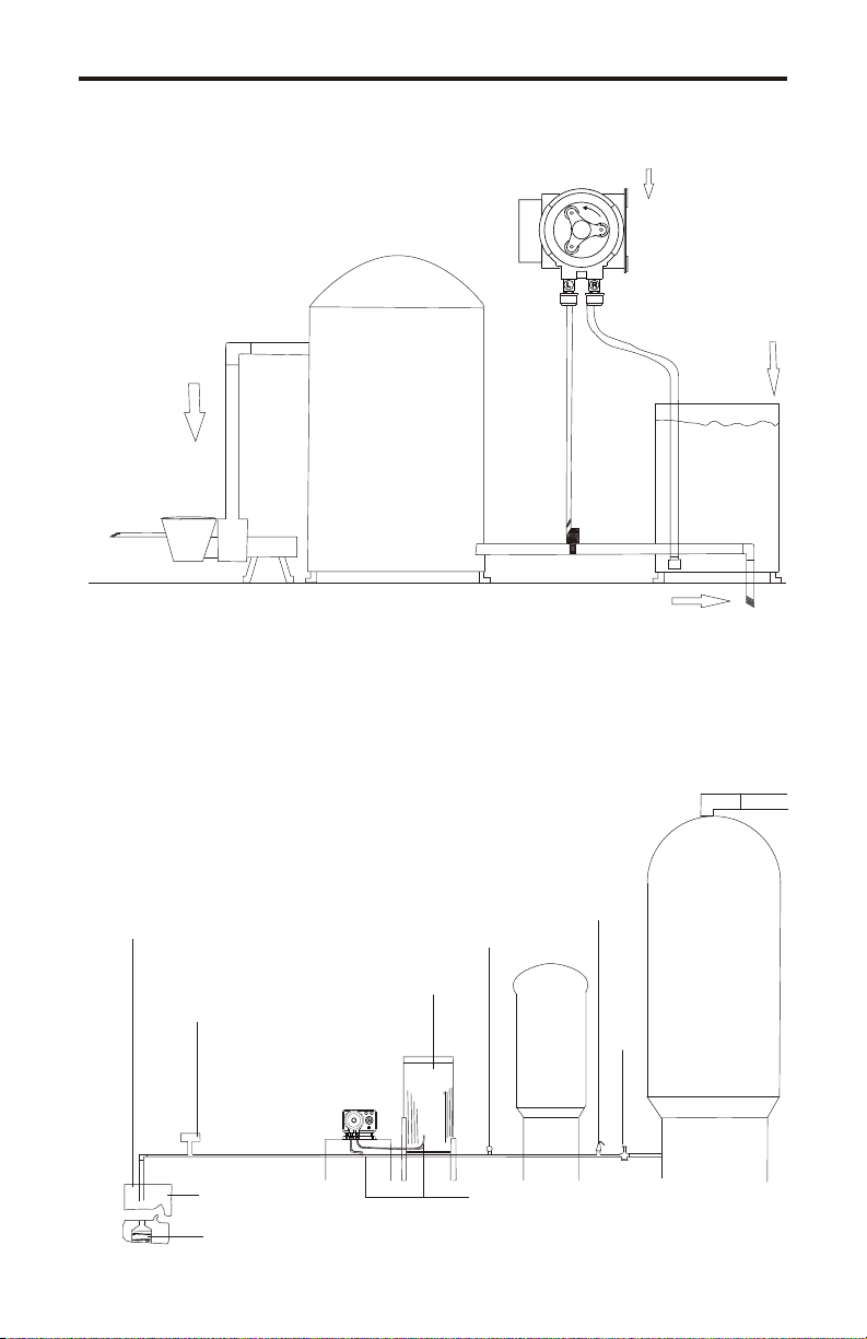
SWIMMING POOLS
Figure 3
CIRCULATION
PUMP
FILTER
Page 4
INJECTOR
SOLUTION
TANK
RETURN
LINE
WATER WELLS
Figure 4
Well cover
Pressure
switch
WELL
Submersible well pump
Pressure
guage
Solution
tank
Pressure
relief
valve
Flooded
Suction Tube
Injector Point
To system
Contact
tank
Drain
Page 7

Page 5
WIRING DIAGRAM
Figure 5
WIRING DIAGRAM
FPU1600 SERIES
(Timer Models Only)
Common
Hot
Earth Ground (green)
Power
Cord
120VAC
220/230 VAC
Cycle Adjustment
Potentiometer
HOT
LOAD
Timer
Board
AC
MOTOR
Neutral
Hot
WIRING COLOR CODES
Figure 6
**************MOTOR************
VOLTAGE HOT COMMON GROUND
115v Black or Yellow Blue Green
230v Black or Yellow Red Green
24v Blue White Green
******** CIRCUIT BOARD*******
FPU1600-T (TIMER MODELS ONLY)
HOTVoltage
COMMON
LOAD
115v
230v
(Load and Input)
Black
Black
(Input)
White
White
(Load)
Red
Red
Page 8

OPERATING INSTRUCTIONS
1. ATTACH THE TUBING AND FITTINGS
CAUTION: Be sure the installation does not constitute a cross
connection. Check local plumbing codes.
A. Install the pump tube assembly into the pump head. (Fig.7)
B. Install the threadless injector (T.l. Fitting), or optional threaded antisyphon valve. (Fig.8 or 10)
C. Connect the flow indicator side of the suction tubing to the pump fitting
marked “R”. The flow indicator must be installed in a vertical position.
D. Trim the other end of the suction tubing so the foot valve assembly will
rest 2 inches from the bottom of the solution tank. This is to prevent
sediment from clogging the strainer.
E. Slide the ceramic weight over the suction tubing and attach the foot
valve assembly.
F. Connect the remaining tubing to the pump tube marked “L”. Trim the
other end of the tubing leaving only enough slack to connect it to the
injector fitting. NOTE: for best results, the discharged tubing should be
installed in a continual up slope.
2. PRIMING
CAUTION - THE USE OF PROTECTIVE CLOTHING AND
GOGGLES IS RECOMMENDED.
Page 6
A.To aid in priming and to reduce vapor lock, hold the discharge tubing in a
continual upward slope AWAY FROM YOUR FACE AND BODY, and above the
injector.
B. Turn the percentage timer to ON or MAX. (Timer Models)
C. Turn on the injector.
D. When the fluid nears the injection end of the tubing, turn OFF the injector
and attach the tube to the T.I. Fitting. (Threadless Injector).
E. Check all connections for leaks.
DO NOT OVER TIGHTEN!
Page 9

Page 7
Pump Tube Lubricant: Place 1 or 2 drops of silicone oil on
each roller to lubricate new pump tubes or when required.
Tubing Replacement
1. 2.
L
R
R
RL
Hold the tube in your right hand with the
fitting marked “R” facing you. Note that
the fitting marked “L” is facing downward
and away from you to the left. The tube
is purposely twisted to allow for the
difference between the inside length and
the outside length of the tube when
installed in the pump head.
Hold the tube with your thumbs over the
“R” and the “L.” The tube will naturally
curve toward the rear of the pump head.
The curve in the tubing is a patented
feature which prevents the pump tube
from running outward and against the
cover.
3. 4.
L
R
Attach the plastic tube fitting (marked “R”)
into the right side of the pump head.
Push the groove of the fitting straight into
the slot. With the pump running, hold the
fitting marked “L’ with your left hand (your
thumb should be covering the “L”).
At the same time, use your right thumb
to guide the tube into the pump head.
With the tubing ridding well between
the rollers, push the fitting marked
“L” into the chamber lock. Be sure
both fittings are pushed all the way in
place.
1. Connect the flow indicator end of the suction tube to pump fitting marked “R.”
Indicator to be vertical.
2. Trim the other end so strainer assembly will hang about one or two inches above
bottom of solution tank (sediment space).
3. Slide the ceramic weight over the end and attach the foot strainer assembly.
4. Connect the discharge tube to the “L” fitting then to the injector fitting.
RL
Page 10

Page 8
OPERATING INSTRUCTIONS (Con’t)
3. ADJUSTING THE OUTPUT(Timer Equipped Models Only)
The pause control knob adjusts the cycle timer’s time on. The model FPU1600
standard cycle timer is set at one minute. (+-10%) Other cycle lengths are available.
To adjust the amount of time on, turn the pause control knob to the correct
setting. ½ equals approximately 30 seconds on. 3/4 equals approximately 45
seconds on, etc.
4. MEASURING THE OUTPUT
This volumetric test will take into account installation factors such as line
pressures, fluid viscosity, specific gravity, etc. This test is the most accurate for
measuring the injector’s output individual installation.
A. With the injector installed under normal operating conditions, place the foot
valve/ strainer in a large graduated container.
B. Fill the container with the chemical to be injected and run the unit until all air is
removed from the suction line.
C. Refill the container if necessary, and with the foot valve in the solution, note
the amount of chemical in the container.
D. Run the injector for a measured amount of time and note the amount of
chemical injected. The longer the testing time, the more accurate the measurement.
MAINTENANCE PROCEDURES
1. ROUTINE MAINTENANCE
The FPU1600 injector is designed to require very little maintenance. However,
inspections should be performed regularly. An inspection log should be kept to
note any changes in performance. This is particularly important when injecting
fluids other than water.
When injecting water only inspect the injector once every month for signs of
leaks, cracks, crazing (shattered look), corrosion or discoloration of the pump
head and tubing. Note all changes in the log.
When injecting fluids other than water, inspect the injector at leased once every
day for the first week of operation, inspect once every week thereafter. Look
for evidence of chemical attack in the pumphead, O-ring, tubing and accessory
valves and fittings. Inspect all parts for leaks, swelling, cracking, crazing,
corrosion, or discoloration. Also inspect the tubing for elasticity. Note all changes
in log.
B. Cracking, crazing, discoloration, etc., During the first week of operation, are
signs of severe chemical attack. If this occurs, immediately remove the injector
from the fluid. Determine which parts are being attacked and replace with parts
that have been manufactured using a more suitable material.
Page 11

Page 9
C. The FPU1600 injector is designed to perform in a variety of installations.
However, the service life of each part in the injector will vary depending on many
factors such as fluid, temperature, pressure, etc. Because of the wide variety of
installations, the FPU1600 has been factory tested for pressure and performance
using water only.* Do not use chemical other than water unless you are satisfied
they are compatible with the injectors construction.
*NOTE: NSF international has tested the FPU1600 injector using two
different fluids, 12 1/2% Sodium Hypochlorite and has found that the
FPU1600T conforms to the requirements of NSF Standard 50.
2. THE PUMP TUBE ASSEMBLY
A. The FPU1600 Pump Tube Assemblies are designed for a service life of at least
800 hours. However, the service life can be adversely affected by the chemicals
used, the amount of back pressure, the motor RPM, and temperature. The
service life of 800 hours is based on the A-002-6 tube tested with water at 70F.
(21C), 0PSI, 45 RPM gearbox.
B. The pump tube assembly should be inspected frequently. Replace the tube if
any cracking, leaking or loss of feed rate occurs.
NOTE: Place 1 or 2 drops of silicone oil on each roller to lubricate new pump
tubes or when required.
3. CLEANING
A. The most common problems occur from deposits that can build up in the foot
valve, injection fitting and pump tube assembly, (wetted parts). Keeping these
parts clean will dramatically increase the life of the injector.
B. For simple maintenance cleaning, remove the injection fitting and footvalve /
strainer. Disassemble and clean the individual parts with clean water. (Fig. 8 or 9)
With these fittings removed, set the pause control to ON and run the injector
using clean water.
C. For removing harsh deposits that can build in the wetted parts.....
1. Flush the system by pumping clean water to remove any chemicals that may
be present.
2. Run a weak solutions of muriatic acid (5%) through the wetted parts.
3. Again flush the system with clean water.
CAUTION
MURIATIC ACID WHEN MIXED WITH OTHER CHEMICALS CAN BE
EXTREMELY DANGEROUS. ALWAYS FLUSH THE SYSTEM WITH CLEAN
WATER BEFORE AND AFTER YOU ACID WASH.
D. When changing the pump tube assemble, always wipe the pumphead to
remove any debris. Clean with soap and water if necessary.
Page 12

Page 10
19
7
1
5
1
2
1
8
F
ro
nt
Vi w
e
4
2
1
Page 13

Page 11
n
ui
Hos g
r
T
I
Mo
to
S
T L S
8
0P
-
PAR
C6
0
1.
9
60
1
P
U
F
o
gK
in nb
n
i
a
e
r
eRt
a Co
ed v
mp
u h
P
1
1
0
.
1A
D
R
l
i
P
-223 h
w
e
r
c 63x-/4
S
8
6
C-
0 2
2.
vr
Coe
d
pe
Pm
u ha
01
A
.
2 0
y
l
b
e
asm
nbx s
t
cio o
Jn
u
J
8
3
-
4 0
2.C
e
en
r
p
r
N
o
OD
”
6
3
/1
.
sy
eAs
b
Pmp u
u T
N
-023
A
3. 0-
p
p
m
m
a
l
C
la
/
W/
W
n
e4
o
on
p
t
i
i
P
Vi
V
2”
e
in
ng
b
i
’
u
b
D T
x 10
D T
”
O u
8 O g
/
” D
/4
4
3
/
t
t1
u
g
N
n
e
b u
b
u e N
u i
u
T
T
- T b 1 O
4 10
4
-6
4
30
3 -
3
3
-
-3 0
C-
.C
.C
26
5
2
3
e
n
n
y
y o
T go
N r n
T g
D
D
OD orp e
O
8 O
/
/4
/4
3 ”
1 ”
1 ”
y
y
s .
s
s y
A
A s .
A s .
be
be
be
p u
p u
u T
P m
P m
P mp u
u T s
u T
n
6
4
-
-
- 0
- 0
A
A 0 -
A 0 2
0 2
-0 2 4
/
b t C
-1
u
2
T
Tu e
0
u
hr
D b
T
D x
” O
”
4” O
8
O 1 ’
/
1
”
3/
1
s
8
t
g
g
i
n
3
n
F
i
i
t
t
g /
p
i
itt
n
i
m
F
.
b
. D
a
I F
.I
T
C
T
.
l
u
T
0
1
V
V
-6
4
6
-4
0 0
0
34
-
4 -
1
C-3
T 4
.
T
.C
8
2
27
F 3
e
e
n
n
re
o
rp en
g
o
y
N r 1 0
o
T
D
D N rp
O
6” O
6
”
1 ”
8 O
/1
/
/
7 D
3
. 7
.
be
y
y
o
s
sy
L
s
3
A
A
A s .
.
e
y
be
b
s
u
u
u e
T s
T b
r As
p T
p
p
m
m
o
u
Pum
P
R lle
N
6 u
-7
- n P
3
2 s
2
2
0
0 -7
0
0
0
0
-
-
-
A
A
A 0
A 0
.
v
n
n
15
ito
ito
1
.
V
V
t
Min
OD
gh
OD
”
1
4”
/
/8
Wei
y.
3
1
r
r
e
ve
l
n
Ass
i
ine
r
a
V
a
r
a
t
tr
o
St
/
o
Time
e/S
c
F
lve
i
lv
c
a
i
n
a
V
m
v
ro
t
t
t
a
o
r
o
o
e
lec
C
F
Fo
E
V
V
6
-
-
0
3-B
2
40
346
34
0
A-
C-
C-
C-3
.
.
1.
0
29
3
3
”
/4
0- 2 x
1
w
e
r
c
s
g
e
in
t
b
er
l
n
u
c
a
u
L
o
pa
Se
2
t
f
y.
d S
d M
a
s
a
a
e
e
Sh
A
s
h
h
r
r
p
p
e
l
m
m
o
Moto
Pu
Pu
R l
1
-
E
1
3
04
03
10
0
-0
-0
-
A
2
A-0
.
.
.
7
6
5 3 3 4
A
v
v
5
0v
0
v
2
3
2
2
24
1
3 v
.
.
.
c 1
n
n.
i
M
Mi
M n
6 e
2
6 e .
1
.
.
.
y
y.
y. 1
s
s
Ass
A
r
r
e
e
m
m
i
Ti
T
c
i
ic
on
on
tr
ct
c
e
le
El
E
C
D
3
32
0
A-
A 02
x
2 ½
3
-
- r
e 0
r w 1
Sc
t
d
un
ea
Mo
h
r
o
t
mp
o
M
Pu
6
5
0
0
0
0
A-
A-
.
.
9
8
y
s
s
r As
r As y
r S c 2 0
m s i
ime
i e
ime As
T S
T
c
ic
i
i T
n
n
n c
o
o
tr
c
ct o
c
le
Ele tr
Ele
G
F
3
3
2
0
A 0
A
- 2
- 2 -
E E r
A 0 3
x
M
He
RP
m.
1
1Alu
b 4
.3
m ly
x
e
s
2
t
n
0- 0
5
x As
ou
.
g
M
n
o
r
h
ar B
to
u
G
M
e
B
o
1
9
2
800
- s i
-
C 30
A-
.
5.
4. C 64
2
1
1
1
P
R M
4
M
M
1
o
RP
RP
F r
4
3
ly
ly
0HZ
/6
m
v
em
e
4
s
s
s
.
s
s y 2
o A b 5
o b 0
A
to
ar B x s
ar B x A
o
G
G
e
e
1 M r
-
-
9
8
8
00
- 4
A
A 00
A 1
3
- 2
.
7
1
5RM
4 P
&
3
o
0HZFr 0
6
/
v
4
.
s
sy2
A
to
o
1M r
9
0
A3
P
RM
4
1
fr
0
6HZo
/
v
5
1
1
.
As
r sy
to
o
-
92M
4
1
A
’
RIN S
N E
G
GA EN
E
OM
T I E G
AC
NT
O
C
M
P
4
& 5R
0
3
o
fr
0
6HZ
/
v
5
1
.
sy1
As
oo
-
92Mtr
0
3
A
P
U .
R
G O
S
T
PA
A E R
P
S R
M
R
P
r 4
f
Zo 1
5H
0/
2
2v 0
.
As
tr sy
oo
-
94M
4
1
A
PM
R
5
3 4
r 0&
o
f
Z
H
20/5
2v 0
tr sy
ooAs.
0394M
A
-
M
1 P
r 4R
o
f
Z
H
0
3v
20/6
y
r s
t
M
ooAs.
4193
A
-
R
PM
& 4
0 5
3
r
o
f
HZ
0
/6
3v
20
y
r s
oAs.
t
M
o
A393
-0-
Page 14

TROUBLE SHOOTING GUIDE
SYMPTOM
POSSIBLE CORRECTIVE
Tube wears out to fast 1. High back pressure
2. Temp. above 105° F
3. Clogged injection
fitting
Injector runs noisy
1. Normal with 14 RPM
2. Worn motor bearing
Injector runs hot
1. Normal heat rise is
approx. 70° F
Solution tank is filling
instead of emptying
1. Suction & Discharge
tubing is reversed
2. Rollers worn far
beyond standard
tolerance
Swollen O-Rings 1. O-Ring material is
not compatible with
chemical being used.
1. MAX PSI = 25
2. Do not install near
a heat source
3. Clean fittings
1. None
2. Replace bearing
1. Do not install near
a heat source
1. Connect suction
tube to fitting marked
“R” and Discharge to
“L”
2. Replace Roller
Assembly
1. Replace with
compatible O-Rings
Cycle Timer is erratic or
run constantly
Pressure is below 25
PSI but chemical is not
injecting
1. Spikes or surges in
electricity caused by
“ORP” or “PH”
controllers
2. Surge protector has
been overlooked
1. Tube assembly is worn
2. Roller Assembly is worn
3. Injection fitting or foot /
valve assembly is clogged
4. Discharge tubing is to
long creating added back
pressure (especially with
high viscosity chemicals)
1. Consult controller
manufacturer
2. Replace timer
board
1. Replace tube assy
2. Replace roller
3. Clean fittings
4. Install injector as
close to injection
point as possible Trim
Discharge tubing
Page 15

NOTES
Page 16

MADEMADE
ININ
USAUSA
OMEGA warrants this unit to be free of defects in materials and workmanship and to give
OMEGA warrants this unit to be free of defects in materials and workmanship and to give
satisfactory service for a period of from date of purchase. OMEGA Warranty adds an
satisfactory service for a period of 13 months from date of purchase. OMEGA Warranty adds an
additional one (1)month grace period to the normal one to cover
additional one (1)month grace period to the normal one (1) year product warranty to cover
handling and shipping time. This ensures that OMEGA’s customers receive maximum coverage on
handling and shipping time. This ensures that OMEGA’s customers receive maximum coverage on
each product. If the unit should malfunction, it must be returned to the factory for evaluation.
each product. If the unit should malfunction, it must be returned to the factory for evaluation.
OMEGA’s Customer Service Department will issue an Authorized Return (AR) number immediately
OMEGA’s Customer Service Department will issue an Authorized Return (AR) number immediately
upon phone or written request. Upon examination by OMEGA, if the unit is found to be defective it
upon phone or written request. Upon examination by OMEGA, if the unit is found to be defective it
will be repaired or replaced at no charge. However, this WARRANTY is void if the unit shows
will be repaired or replaced at no charge. However, this WARRANTY is void if the unit shows
evidence of having been tampered with or shows evidence of being damaged as a result of
evidence of having been tampered with or shows evidence of being damaged as a result of
excessive corrosion; or current, heat, moisture, or vibration; improper specification; misapplication;
excessive corrosion; or current, heat, moisture, or vibration; improper specification; misapplication;
misuse or other operating conditions outside of OMEGA’s control. Components which wear or which
misuse or other operating conditions outside of OMEGA’s control. Components which wear or which
are damaged by misuse are not warranted. These include contact points, fuses, and triacs.
are damaged by misuse are not warranted. These include contact points, fuses, and triacs.
OMEGA is glad to offer suggestions on the use of it’s various products. Nevertheless,
OMEGA is glad to offer suggestions on the use of it’s various products. Nevertheless,
OMEGA only warrants that the parts manufactured by it will be as specified and free of
OMEGA only warrants that the parts manufactured by it will be as specified and free of
defects.
defects.
OMEGA MAKES NO OTHER WARRANTIES OR REPRESENTATIONS OF ANY KIND
OMEGA MAKES NO OTHER WARRANTIES OR REPRESENTATIONS OF ANY KIND
WHATSOEVER, EXPRESSED OR IMPLIED, EXCEPT THAT OF TITLE AND ALL IMPLIED
WHATSOEVER, EXPRESSED OR IMPLIED, EXCEPT THAT OF TITLE AND ALL IMPLIED
WARRANTIES INCLUDING ANY WARRANTY OF MERCHANTABILITY AND FITNESS
WARRANTIES INCLUDING ANY WARRANTY OF MERCHANTABILITY AND FITNESS
FOR A PARTICULAR PURPOSE ARE HEREBY DISCLAIMED.
FOR A PARTICULAR PURPOSE ARE HEREBY DISCLAIMED.
LIMITATION OF LIABILITY: The remedies of purchaser set forth herein are exclusive and the
LIMITATION OF LIABILITY: The remedies of purchaser set forth herein are exclusive and the
total liability of OMEGA with respect to this order, whether based on contract, warranty,
total liability of OMEGA with respect to this order, whether based on contract, warranty,
negligence, indemnification, strict liability or otherwise, shall not exceed the purchase price
negligence, indemnification, strict liability or otherwise, shall not exceed the purchase price
of the component upon which liability is based. In no event shall OMEGA be liable for
of the component upon which liability is based. In no event shall OMEGA be liable for
consequential, incidental or special damages.
consequential, incidental or special damages.
Every precaution for accuracy has been taken in the preparation of this manual; however, OMEGA
Every precaution for accuracy has been taken in the preparation of this manual; however, OMEGA
ENGINEERING, INC. Neither assumes responsibility for any omissions or errors that may appear
ENGINEERING, INC. Neither assumes responsibility for any omissions or errors that may appear
nor assumes liability for any damages that result from the use of the products in accordance with
nor assumes liability for any damages that result from the use of the products in accordance with
the information contained in this manual.
the information contained in this manual.
SPECIAL CONDITION
SPECIAL CONDITION: Should this equipment be used in or with any nuclear installation or activity,
purchaser will indemnify OMEGA and hold OMEGA harmless from any liability or damage
purchaser will indemnify OMEGA and hold OMEGA harmless from any liability or damage
whatsoever arising out of the use of the equipment in such a manner.
whatsoever arising out of the use of the equipment in such a manner.
: Should this equipment be used in or with any nuclear installation or activity,
WARRANTY/DISCLAIMER
13 months
(1) year product warranty
RETURN REQUESTS / INQUIRIES RETURN REQUESTS / INQUIRIES
Direct all warranty and repair requests/inquiries to the OMEGA ENGINEERING
Direct all warranty and repair requests/inquiries to the OMEGA ENGINEERING
Customer Service Department. BEFORE RETURNING ANY PRODUCT(S) TO OMEGA,
Customer Service Department. BEFORE RETURNING ANY PRODUCT(S) TO OMEGA,
PURCHASER MUST OBTAIN AN AUTHORIZED RETURN (AR) NUMBER FROM
PURCHASER MUST OBTAIN AN AUTHORIZED RETURN (AR) NUMBER FROM
OMEGA’S CUSTOMER SERVICE DEPARTMENT (IN ORDER TO AVOID
OMEGA’S CUSTOMER SERVICE DEPARTMENT (IN ORDER TO AVOID
PROCESSING DELAYS). The assigned AR number should then be marked on the
PROCESSING DELAYS). The assigned AR number should then be marked on the
outside of the return package and on any correspondence.
outside of the return package and on any correspondence.
FOR WARRANTY RETURNS, please have FOR NON WARRANTY REPAIRS OR
The following information available CALIBRATION, consult OMEGA for
1. P.O. Number under which the product current repair/calbration charges. Have
was PURCHASED. Information before contacting OMEGA.
2. Model and serial number of the product 1. P.O. Number to cover the COAST of
under warranty, and the repair/ calibration.
3. Repair Instructions and/or specific 2. Model and serial number of product,
Problems relative to the Product. and
3. Repair instructions and/or specific
Problems relative to the product
OMEGA’s policy is to make running changes, not model changes, whenever an
OMEGA’s policy is to make running changes, not model changes, whenever an
improvement is possible. This affords our customers the latest in technology and
improvement is possible. This affords our customers the latest in technology and
engineering.OMEGA is a registered trademark of OMEGA ENGINEERING,
engineering.OMEGA is a registered trademark of OMEGA ENGINEERING,
INC.©Copyright 1995 OMEGA ENGINEERING, INC. All rights reserved. This
INC.©Copyright 1995 OMEGA ENGINEERING, INC. All rights reserved. This
documentation may not be copied, photocopied, reproduced, translated, or reduced to
documentation may not be copied, photocopied, reproduced, translated, or reduced to
any electronic medium or machine-readable form, in whole or in part, without written
any electronic medium or machine-readable form, in whole or in part, without written
consent of OMEGA ENGINEERING, INC.
consent of OMEGA ENGINEERING, INC.
Page 17

Where Do I Find Everything I Need For
Process Measurement and Control?
OMEGA... Of Course!
Shop on line at www.Omega.com
TEMPERATURE
Thermocouple, RTD & Thermistor Probes, Connectors, Panels & Assemblies
Wire: Thermocouple, RTD & Thermistor
Calibrations & Ice Point References
Recorders, Controllers & Process Monitors
Infrared Pyrometers
PRESSURE / STRAIN FORCE
Transducers & Strain Gauges
Load Cells & Pressure Gauge
Displacement Transducers
Instrumentation & Accessories
FLOW / LEVEL
Rotameters, Gas Mass Flowmeters & Flow Computers
Air Velocity Indicators
Turbine / Paddlewheel Systems
Totalizers & Batch Controllers
pH / CONDUCTIVITY
pH Electrodes, Testers & Accessories
Benchtop / Laboratory Meters
Controllers, Calibrators, Simulators & Pumps
Industrial pH & Conductivity Equipment
DATA ACQUISITION
Thermocouple, RTD & Thermistor Probes, Connectors, Panels & Assemblies
Wire: Thermocouple, RTD & Thermistor
Calibrations & Ice Point References
Recorders, Controllers & Process Monitors
Infrared Pyrometers
HEATERS
Heating Cable
Cartridge & Strip Heaters
Immersion & Band Heaters
Flexible Heaters
Laboratory Heaters
ENVIRONMENTAL MONITORING AND CONTROL
Metering & Control Instrumentation
Refractometers
Pumps & Tubing
Air, Soil & Water Monitors
Industrial Water & Wastewater Treatment
pH, Conductivity & Dissolved Oxygen Instruments
M2060/0805
 Loading...