

Page 1
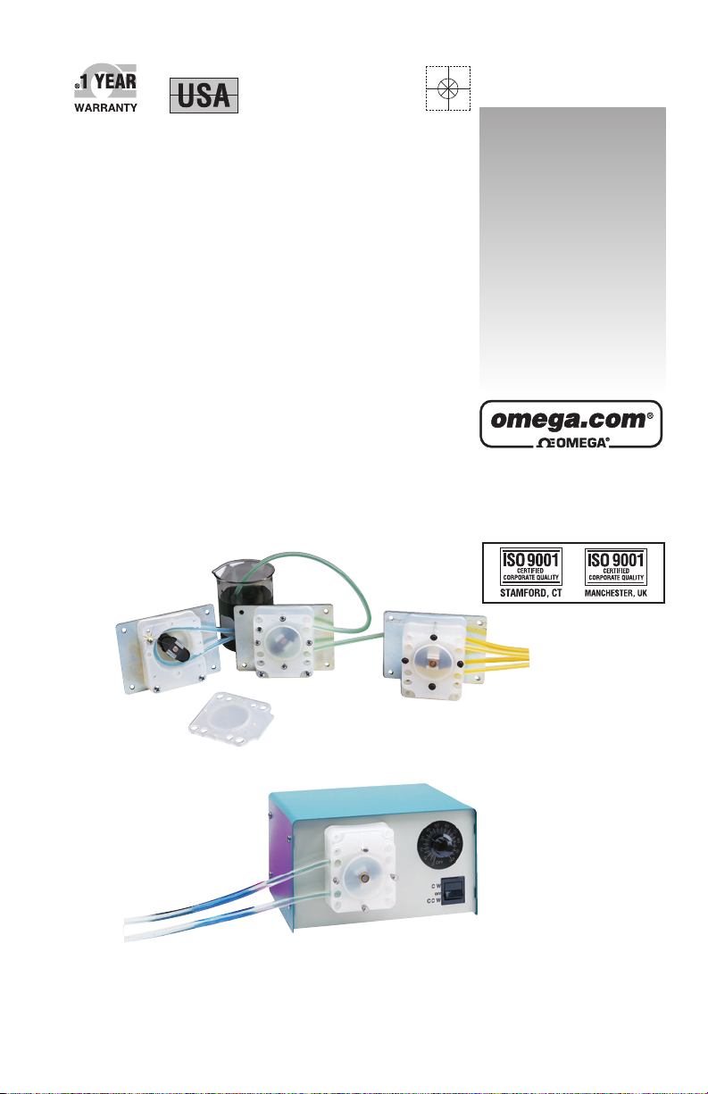
FPU100 Series
FPU250 Series
FPU100 AND 250 SERIES
OMEGAFLEX®PERISTALTIC PUMPS
MADE IN
omega.com
e-mail: info@omega.com
For latest product manuals:
omegamanual.info
User’s Guide
Shop online at
Page 2

1
INTRODUCTION
2
INTRODUCTION
General Description
The OMEGA®peristaltic pump is self-priming and can handle a wide
variety of viscosities (from air to heavy slurries) with positive
displacement.
The OMEGA
®
peristaltic pump can be used to pump fluids or gases
without contamination of the pump - the material contacts only the
tubing. The positive displacement feature makes this pump ideal for
metering applications. Each revolution of the roller assembly delivers a
precise amount of fluid.
The easy changeability of the OMEGA
®
peristaltic pump tubing makes
this the ideal pump for diverse quick change repetitive pumping jobs.
Flexible, reliable and cost efficient, the OMEGA
®
peristaltic pump can
fill most all of your fluid movement requirements.
Specifications
1. Priming Unit is self-priming and will hold vacuum when turned
off.
2. Operation: Pump can run dry without damage.
3. Weight: See model information chart.
4. Capacity: From 3mL/min to 987mL/min (see model information
chart).
5. Construction: High strength plastics and long-lasting alloy metals.
6. Maximum Head Pressure: 57 feet of water.
7. Maximum Suction Lift: 28 feet of water.
8. Maximum System Pressure: 20 psi continuous, 25 psi intermittent.
9. Certification: All motors are UL listed.
10. Rating: All gearmotors are rated for 100% continuous duty.
Page 3
2
OPERATIONAL INFORMATION
3
OPERATIONAL INFORMATION
Installation Instructions
Power Requirements: Voltage and frequency of power supply must be
the same as shown on unit.
Wiring Connections: All wiring and electrical connections must comply
with national electrical codes and local electrical codes.
Mounting:
a) Mount OEM model mounting bracket to any flat, rigid surface, using
four #10-32 screws.
b) Case enclosed model may be placed on any flat surface, assuring
space is provided at the back of the case for air circulation through
ventilation holes.
Mounting Location: Pump should be used in a dry location with an
adequate supply of cooling air. The ambient temperature should not
exceed 25°C.
This unit should not be used outdoors or in hazardous
locations.
Instructions for Optional Timer
1. Rotate the program disc in the direction of the arrows to align the
correct time of day with the time mark.
2. Set the desired switching program by pushing the switch actuators
toward the center of the time switch. Each actuator provides a 15
minute “ON” time. The now visible orange area(s) indicate the
switch “ON” period
WARNING
Page 4
3
FPU SERIES
ROLLER AND TUBING SELECTION
4
FPU SERIES
ROLLER & TUBING SELECTION
Use the following color coded rollers with the appropriate tubing ID:
Roller Color Tubing ID mL Per Revolution
Black
1
⁄4"3.5
Black
3
⁄16"2.1
Red
1
⁄8"0.84
Red
1
⁄6"0.21
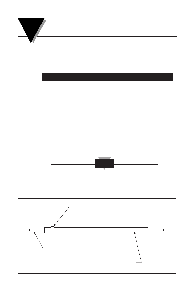
Instructions for 1/16" Tubing Assembly
Insert 1⁄16" tubing into the sleeve and pull out desired length of 1⁄16"
tubing. Secure
1
⁄16" tubing by placing the tie fastener approximately 1⁄4"
from one end of the sleeve and tighten fastener so that
1
⁄16" tubing is not
easily moved. Be careful not to collapse the inner tubing by overtightening the tie fastener. Install the tubing with the tie fastener on the
inlet side of the pump.
Make sure the tie fastener is on the outside of the pump
housing and is not interfering with the roller assembly.
NOTE
PLASTIC TIE FASTENER
1/16" I. D. TUBE
3/16" I. D. SLEEVE
Page 5

4
ASSEMBLY INSTRUCTIONS
5
ASSEMBLY INSTRUCTIONS
1. Assemble mounting plate (4) and pump housing (5) to gearmotor (3)
with with three #10-32 x 1
1
⁄4" long screws and one #8-32 x 7⁄8" long
screw (2).
2. Slide white plastic washer (8) onto motor shaft. Press roller bracket
assembly (9) onto the motor shaft with the four self-locking teeth
toward the gearmotor. (As shown in the view above.)
3. Insert tubing (6) into pump. housing (5) inlet and work tube into
roller race as you rotate the roller bracket assembly. See details on
page 5.
4. Assemble pump cover (10) to pump housing. (5) with four #8-32 x
5
⁄8"
long screws (11).
Page 6

5
TUBE INSPECTION AND REPLACEMENT
6
TUBE INSPECTION AND REPLACEMENT
Tubing Inspection:
Inspect all tubing regularly and replace it if deterioration occurs. Use
the following instructions to replace pump tubing.
Tubing Replacement
1. Disconnect the power to the pump.
2. Disconnect the suction and discharge tubing from the tubing.
3. Remove four screws and pump cover.
4. Remove old pump tubing and discard.
5. Clean roller race, removing any particles that could damage tubing.
6. Position the roller bracket assembly as shown in Fig. 1.
7. Push the new tubing into the inlet port anchoring the tubing in
grippers (see Fig. 2) while rotating the roller bracket assembly.
8. Continue to rotate the roller bracket assembly, pushing the tubing
into the roller race.
9. Finally, insert the tubing into the outer port (Fig. 4), and replace the
cover and screws.
Page 7

6
OMEGA®VARIABLE SPEED DRIVES
FPU250 SERIES
7
OMEGA®VARIABLE SPEED DRIVES
SERIES FPU 250
OMEGA®variable speed drives are powered by a DC gearmotor. A
specially designed electronic speed control system provides smooth
acceleration control over the entire flow range. The three position
on/off switch allows the user to maintain speed setting when unit is
turned off or reversed. This unit is designed for continuous operation at
any speed. All variable speed drives are rated for continuous duty at
25°C ambient.
Fuse: Replace with type AGC-1/2 Amp. Use AGC-1 Amp for dual head
pump.
Alternate Tubing Replacement Method for Medium and High
Variable Speed Units
With unit running at high RPM, pull old tubing out from outlet port of
pump. Install new tube by inserting into inlet port; continue feeding
tube
1
⁄4" in at a time, allowing the roller assembly to push tubing until
tube extends out from outlet port. Pull tubing from outlet port until
desired tubing extension is obtained. Run unit for about one minute to
allow tube to seat properly.
Depending on pump model, tubing in use and fluid being
pumped, roller assembly may stop rotating when
speed/flow control is set at the low end range. Avoid
prolonged operation in the stalled position for longer motor
life.
CAUTION
Omega Water Tube Case Amps
Model Range (inner dia.) Dimensions @ Weight
No. (ml/min) mm (in.) cm (in.) RPM 60Hz kgs. (lbs)
FPU251 0.36-5.5 1.59 (1⁄16) 22.5 x 14.2 x 19.1 (8.85 x 5.6 x 7.5) 1.5 to 26 0.5 3.63 (8)
FPU252 3.0-50 4.76 (3⁄16) 22.5 x 14.2 x 19.1 (8.85 x 5.6 x 7.5) 1.5 to 26 0.5 3.63 (8)
FPU253 6.0-90 6.35 (1⁄4) 22.5 x 14.2 x 19.1 (8.85 x 5.6 x 7.5) 1.5 to 26 0.5 3.63 (8)
FPU254 0.9-24 1.59 (1⁄16) 22.5 x 14.2 x 19.1 (8.85 x 5.6 x 7.5) 4 to 114 0.5 3.63 (8)
FPU255 8.0-220 4.76 (3⁄16) 22.5 x 14.2 x 19.1 (8.85 x 5.6 x 7.5) 4 to 114 0.5 3.63 (8)
FPU256 14-400 6.35 (1⁄4) 22.5 x 14.2 x 19.1 (8.85 x 5.6 x 7.5) 4 to 114 0.5 3.63 (8)
FPU257 1.7-49 1.59 (1⁄16) 22.5 x 14.2 x 19.1 (8.85 x 5.6 x 7.5) 8 to 228 1 3.63 (8)
FPU258 15-440 4.76 (3⁄16) 22.5 x 14.2 x 19.1 (8.85 x 5.6 x 7.5) 8 to 228 1 3.63 (8)
FPU259 28-800 6.35 (1⁄4) 22.5 x 14.2 x 19.1 (8.85 x 5.6 x 7.5) 8 to 228 1 3.63 (8)
Page 8

7
REPLACEMENT PARTS
8
MODEL NO. DESCRIPTION (ID X OD)
FPU16-N 1/16" X 1/8" Norprene
®
Tubing
FPU16-S 1/16" X 1/8" Silicone Tubing
FPU18-N 1/8" X 3/8" Norprene
®
Tubing
FPU18-S 1/8" X 3/8" Silicone Tubing
FPU316-H 3/16" X 3/8" Norprene® Tubing
FPU316-S 3/16" X 3/8" Silicone Tubing
FPU14-N 1/4" X 7/16" Norprene® Tubing
FPU15-S 1/4" X 7/16" Silicone Tubing
TUBING REPLACEMENT CHART
REPLACEMENT PARTS
ITEM NUMBER PART
NUMBER REQUIRED DESCRIPTION
1 1 Fan
2 1 Screw, Gearmotor
3 1 Gearmotor
4 1 Mounting Plate or Case (Enclosure)
5 1 Pump Housing
6 1 Tubing (See Tubing Replacement Chart)
7 3 Screws, Pump Housing
8 1 Washer
9 1 Roller Bracket Assembly
10 1 Pump Housing Cover
11 4 Screws, Pump Housing Cover
12 1 Motor Starter (Not all models)
Page 9

8
FPU SERIES
AC AND DC MODELS
9
FPU SERIES - AC MODELS, OEM Style, Fixed Speed
FPU SERIES - DC MODELS, OEM Style, Fixed Speed
130.0 (5.12) A
110.2 (4.34)
77.7
(3.06)
5.59 DIA. (0.22) - (4) PLCS.
9.9 (0.39)
9.4 (0.37)
76.2
(3.74)
(3.00)
26.2
(1.03)
95.0
DIMENSIONS mm (in.)
The following models require a
motor starter as shown in the
drawing at right.
FPU-123 Single Head
*
FPU-124 Single Head
*
FPU-125 Single Head
*
FPU-122 DUAL Dual Head
*
FPU-123 DUAL Dual Head
*
FPU-124 DUAL Dual Head
*
*These models are not UL listed.
33.3
(1.31)
33.3
(1.31)
24.4
(0.96)
1.3
(0.5)
24.4
(0.96)
1.3 THK.
(0.5)
B
(3.65)
92.7
38.1
(1.5)
66.6
(2.62)
11.9
(0.47)
6.4 (0.25) O. C.
TERMINALS
66.6
(2.62)
11.9
(0.47)
MOTOR
STARTER
98.3
(3.87)
1.27
(0.05)
30.0
(1.18)
90.2
(3.55)
5.59 DIA. (0.22), 4 HOLES
77.7
(3.06)
110.2
(4.34)
130.0
(5.12)
(1.50)
62.5
(2.46)
76.2
(3.00)
DIMENSIONS mm (in.)
38.1
76.2
(3.00)
9.9
(0.39)
9.4
(0.37)
95.0
(3.74)
Page 10

9
MODEL INFORMATION CHART
10
Page 11

1
FPU100 AND FPU250 SERIES
OMEGAFLEX
®
PERISTALTIC PUMPS
11
NOTES:
Page 12

M1116-0404
It is the policy of OMEGA Engineering, Inc. to comply with all worldwide safety and EMC/EMI regulations that apply. OMEGA is constantly pursuing
certification of its products to the European New Approach Directives. OMEGA will add the CE mark to every appropriate device upon certification.
The information contained in this document is believed to be correct, but OMEGA accepts no liability for any errors it contains, and reserves the
right to alter specifications without notice.
WARNING: These products are not designed for use in, and should not be used for, human applications.
WARRANTY/DISCLAIMER
OMEGA ENGINEERING, INC. warrants this unit to be free of defects in materials and workmanship for a period of 13 months from
date of purchase. OMEGA’s WARRANTY adds an additional one (1) month grace period to the normal one (1) year product
warranty to cover handling and shipping time. This ensures that OMEGA’s customers receive maximum coverage on each
product.
If the unit malfunctions, it must be returned to the factory for evaluation. OMEGA’s Customer Service Department will issue an
Authorized Return (AR) number immediately upon phone or written request. Upon examination by OMEGA, if the unit is found to be
defective, it will be repaired or replaced at no charge. OMEGA’s WARRANTY does not apply to defects resulting from any action of the
purchaser, including but not limited to mishandling, improper interfacing, operation outside of design limits, improper repair, or
unauthorized modification. This WARRANTY is VOID if the unit shows evidence of having been tampered with or shows evidence of
having been damaged as a result of excessive corrosion; or current, heat, moisture or vibration; improper specification;
misapplication; misuse or other operating conditions outside of OMEGA’s control. Components in which wear is not warranted,
include but are not limited to contact points, fuses, and triacs.
OMEGA is pleased to offer suggestions on the use of its various products. However, OMEGA neither assumes responsibility
for any omissions or errors nor assumes liability for any damages that result from the use of its products in accordance with
information provided by OMEGA, either verbal or written. OMEGA warrants only that the parts manufactured by the
company will be as specified and free of defects. OMEGA MAKES NO OTHER WARRANTIES OR REPRESENTATIONS OF ANY
KIND WHATSOEVER, EXPRESSED OR IMPLIED, EXCEPT THAT OF TITLE, AND ALL IMPLIED WARRANTIES INCLUDING ANY
WARRANTY OF MERCHANTABILITY AND FITNESS FOR A PARTICULAR PURPOSE ARE HEREBY DISCLAIMED. LIMITATION
OF LIABILITY: The remedies of purchaser set forth herein are exclusive, and the total liability of OMEGA with respect to this
order, whether based on contract, warranty, negligence, indemnification, strict liability or otherwise, shall not exceed the
purchase price of the component upon which liability is based. In no event shall OMEGA be liable for consequential,
incidental or special damages.
CONDITIONS: Equipment sold by OMEGA is not intended to be used, nor shall it be used: (1) as a “Basic Component” under 10 CFR
21 (NRC), used in or with any nuclear installation or activity; or (2) in medical applications or used on humans. Should any Product(s)
be used in or with any nuclear installation or activity, medical application, used on humans, or misused in any way, OMEGA assumes
no responsibility as set forth in our basic WARRANTY/ DISCLAIMER language, and, additionally, purchaser will indemnify OMEGA and
hold OMEGA harmless from any liability or damage whatsoever arising out of the use of the Product(s) in such a manner.
RETURN REQUESTS / INQUIRIES
Direct all warranty and repair requests/inquiries to the OMEGA Customer Service Department. BEFORE RETURNING ANY
PRODUCT(S) TO OMEGA, PURCHASER MUST OBTAIN AN AUTHORIZED RETURN (AR) NUMBER FROM OMEGA’S CUSTOMER
SERVICE DEPARTMENT (IN ORDER TO AVOID PROCESSING DELAYS). The assigned AR number should then be marked on the
outside of the return package and on any correspondence.
The purchaser is responsible for shipping charges, freight, insurance and proper packaging to prevent breakage in transit.
FOR WARRANTY
RETURNS, please have the following informa-
tion available BEFORE contacting OMEGA:
1. Purchase Order number under which the product was
PURCHASED,
2. Model and serial number of the product under warranty, and
3. Repair instructions and/or specific problems relative to the
product.
FOR NON-WARRANTY REPAIRS,
consult OMEGA for current repair charges. Have the following information available BEFORE contacting OMEGA:
1. Purchase Order number to cover the COST of the repair,
2. Model and serial number of the product, and
3. Repair instructions and/or specific problems relative to
the product.
OMEGA’s policy is to make running changes, not model changes, whenever an improvement is possible. This affords our customers the latest in
technology and engineering.
OMEGA is a registered trademark of OMEGA ENGINEERING, INC.
© Copyright 2008 OMEGA ENGINEERING, INC. All rights reserved. This document may not be copied, photocopied, reproduced, translated, or
reduced to any electronic medium or machine-readable form, in whole or in part, without the prior written consent of OMEGA ENGINEERING, INC.
Servicing North America:
U.S.A.: One Omega Drive, Box 4047
ISO 9001 Certified
Stamford, CT 06907-0047
Tel: (203) 359-1660 FAX: (203) 359-7700
e-mail: info@omega.com
Canada: 976 Bergar
Laval (Quebec) H7L 5A1, Canada
Tel: (514) 856-6928 FAX: (514) 856-6886
e-mail: info@omega.ca
For immediate technical or application assistance:
U.S.A. and Sales Service: 1-800-826-6342/1-800-TC-OMEGA
®
Canada: Customer Service: 1-800-622-2378/1-800-622-BEST
®
Engineering Service: 1-800-872-9436/1-800-USA-WHEN
®
Mexico: En Espan˜ol: (001) 203-359-7803 e-mail:espanol@omega.com
FAX: (001) 203-359-7807 info@omega.com.mx
OMEGAnet®Online Service Internet e-mail
omega.com info@omega.com
Servicing Europe:
Czech Frystatska 184, 733 01 Karviná, Czech Republic
Republic: TEL: +420 (0)59 6311899
FAX: +420 (0)59 6311114
Tol Free: 0800-1-66342
e-mail: info@omegashop.cz
Germany/ Daimlerstrasse 26, D-75392 Deckenpfronn, Germany
Austria: Tel: +49 (0)7056 9398-0
FAX: +49 (0)7056 9398-29
Toll Free in Germany: 0800 639 7678
e-mail: info@omega.de
United One Omega Drive, River Bend Technology Centre
Kingdom: Northbank, Irlam, Manchester
ISO 9001 Certified
M44 5BD United Kingdom
Tel: +44 (0)161 777 6611
FAX: +44 (0)161 777 6622
Toll Free in United Kingdom: 0800-488-488
e-mail: sales@omega.co.uk
 Loading...