

Page 1
User's Guide
Shop online at
omega.com
email: Info@omega.com
For latest product manuals:
omegamanual.Info
FPR310
FPR300
FPR300/310 SERIES
Low-Flow Meter
Page 2

Servicing North America:
U.S.A.: One Omega Drive, P.O. Box 4047
ISO 9001 Certified
Stamford, CT 06907-0047
TEL: (203) 359-1660 FAX: (203) 359-7700
e-mail: info@omega.com
Canada: 976 Bergar
Laval (Quebec) H7L 5A1, Canada
TEL: (514) 856-6928 FAX: (514) 856-6886
e-mail: info@omega.ca
For immediate technical or application assistance:
U.S.A. and Canada: Sales Service: 1-800-826-6342 / 1-800-TC-OMEGA
®
Customer Service: 1-800-622-2378 / 1-800-622-BEST
®
Engineering Service: 1-800-872-9436 / 1-800-USA-WHEN
®
TELEX: 996404 EASYLINK: 62968934 CABLE: OMEGA
Mexico: En Espan˜ol: (001) 203-359-7803 e-mail: espanol@omega.com
FAX: (001) 203-359-7807 info@omega.com.mx
Servicing Europe:
Benelux: Postbus 8034, 1180 LA Amstelveen, The Netherlands
TEL: +31 (0)20 3472121 FAX: +31 (0)20 6434643
Toll Free in Benelux: 0800 0993344
e-mail: sales@omegaeng.nl
Czech Republic: Frystatska 184, 733 01 Karviná, Czech Republic
TEL: +420 (0)59 6311899 FAX: +420 (0)59 6311114
Toll Free: 0800-1-66342 e-mail: info@omegashop.cz
France: 11, rue Jacques Cartier, 78280 Guyancourt, France
TEL: +33 (0)1 61 37 2900 FAX: +33 (0)1 30 57 5427
Toll Free in France: 0800 466 342
e-mail: sales@omega.fr
Germany/Austria: Daimlerstrasse 26, D-75392 Deckenpfronn, Germany
TEL: +49 (0)7056 9398-0 FAX: +49 (0)7056 9398-29
Toll Free in Germany: 0800 639 7678
e-mail: info@omega.de
United Kingdom: One Omega Drive, River Bend Technology Centre
ISO 9002 Certified
Northbank, Irlam, Manchester
M44 5BD United Kingdom
TEL: +44 (0)161 777 6611 FAX: +44 (0)161 777 6622
Toll Free in United Kingdom: 0800-488-488
e-mail: sales@omega.co.uk
OMEGAnet®Online Service Internet e-mail
omega.com i n f o @ o m e g a . c o m
It is the policy of OMEGA Engineering, Inc. to comply with all worldwide safety and EMC/EMI
regulations that apply. OMEGA is constantly pursuing certification of its products to the European New
Approach Directives. OMEGA will add the CE mark to every appropriate device upon certification.
The information contained in this document is believed to be correct, but OMEGA accepts no liability for any
errors it contains, and reserves the right to alter specifications without notice.
WARNING: These products are not designed for use in, and should not be used for, human applications.
Page 1
Page 3
GENERAL INFORMATION, FEATURES, SPECIFICATIONS
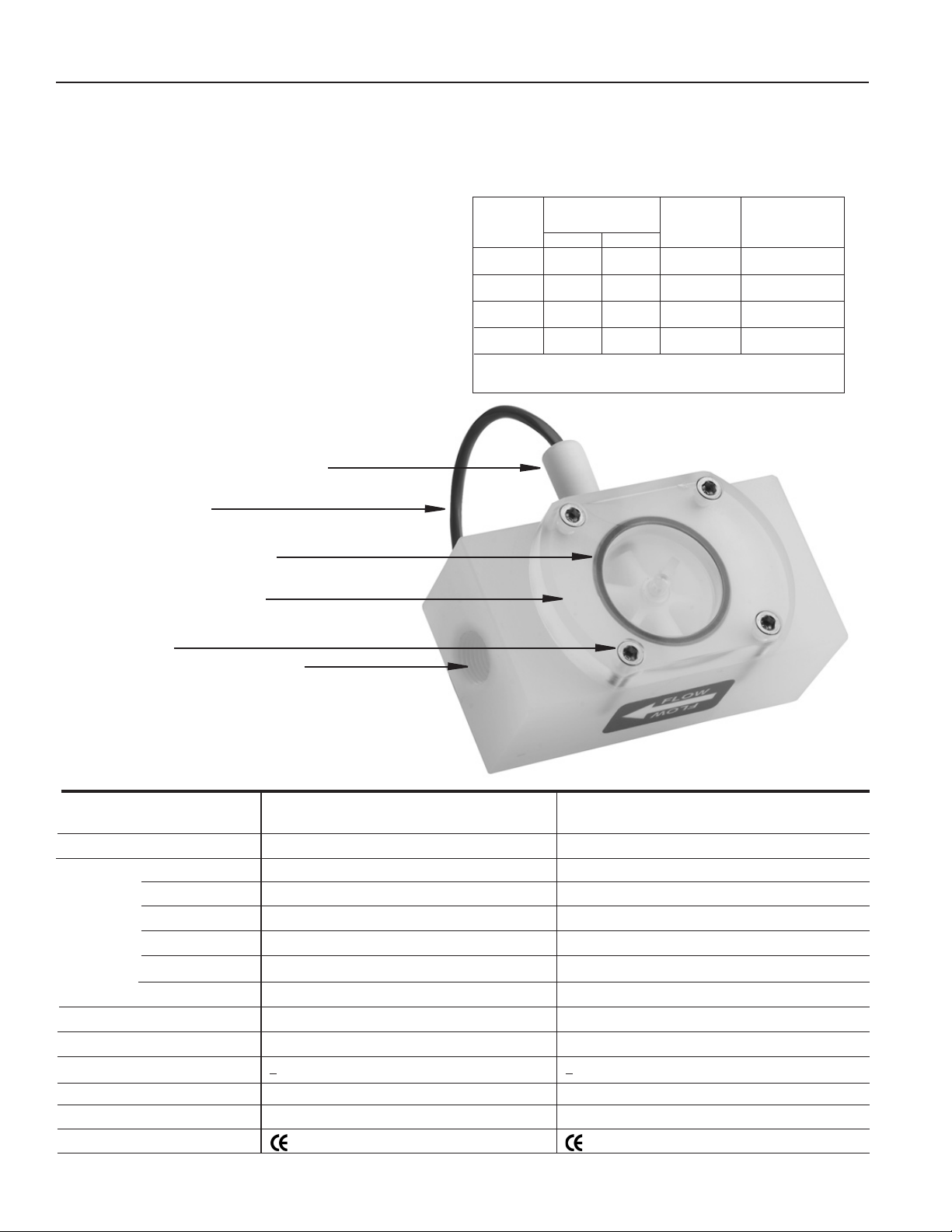
These versatile impeller owmeters are available in 3/8", 1/2”,
3/4”, and 1" nominal pipe sizes with female NPT threads (SAE
optional). They employ jewel bearings to allow for very low
minimum ow rates and superior life.
With a body material of polypropylene, the FPR300 is an eco-
nomical choice for metering water or low corrosion uids. The
lens cover is available in a choice of materials: acrylic for visual
ow indication of low-corrosive uids; polypropylene when more
corrosion resistance is needed. The standard rotor assembly is
PVDF with tungsten carbide shaft (ceramic shaft optional). The
O-ring is EPDM.
The FPR310 offers greater chemical resistance with a PTFE body
and cover, PTFE-coated FKM O-ring, and standard PVDF/ceramic
rotor assembly (carbide shaft optional).
FEATURES
Thread-in Sensor, Field Replaceable,
6-24 Vdc pulse
18’ Sensor Cable
Removable Lens Assembly
The pulse output of these meters is compatible with many different types of controls. For metering pump pacing or interfacing
with lowspeed counters, a pulse divider is recommended.
FLOW RANGE
*K-Factor
Model #
(Pulses/Gal)
FPR300 FPR310
FPR301/311 1417 1394 0.07-5 0.27-18.9
Gal/Min Liter/Min
FPR302/312 658 634 0.1-10 0.38-37.9
FPR303/313 468 476 0.2-20 0.75-75
FPR304/314 254 250 0.5-40 1.9-150
*Nominal K-factors (based on averages) for standard 2-magnet FPR310 and
FPR300. High resolution (6-magnet) K-factors are approximately tripled.
Standard Acrylic Top (SPX)
Hex Screws
Female NPT Ports (SAE optional)
(Internal)
Jewel bearings
PVDF/Carbide or PVDF/Ceramic Rotor Assembly
EPDM (FPR300) or PTFE-coated FKM (FPR310) O-ring
SPECIFICATIONS*
Connection Ports
Sensor Cable
Materials Body
Rotor
Shaft
O-Ring
Bearings
Cover
Maximum Temperature
Maximum Pressure
Accuracy
Power
Outputs
Regulatory
*Specifications subject to change
FPR300 FPR310
3/8”, 1/2”, 3/4”, 1”, Female NPT thread
(SAE optional)
18 feet standard (Maximum cable run 2000 ft.)
Polypropylene
PVDF
Nickel tungsten carbide (zirconia ceramic optional)
EPDM (PTFE-coated FKM optional)
Ruby ring and ball
Acrylic (Polypro optional)
160˚ F (70˚ C)
150 PSI (10 bar)
+1% of full scale
5-24 Vdc, 2 mA min
Current sinking pulse, 6-24 Vdc
Mark (Standard Power Only)
Page 2
FPR300
shown
3/8”, 1/2”, 3/4”, 1”, Female NPT thread
(SAE optional)
18 feet standard (Maximum cable run 2000 ft.)
PTFE
PVDF
Zirconia ceramic (silicon carbide optional)
PTFE-coated FKM (EPDM optional)
Ruby ring and ball
PTFE
160˚ F (70˚ C)
150 PSI (10 bar)
+1% of full scale
5-24 Vdc, 2 mA min
Current sinking pulse, 6-24 Vdc
Mark (Standard Power Only)
Page 4

Red
White
Black
Red
White
Black
Signal
+
DC Voltage
Ground
Signal
+
DC Voltage
Ground
Input Designed for Current
Sinking (NPN) Devices
Input Designed for Current
Sourcing (PNP) Devices
2.2K Ohm Pull-up
Resistor
INSTALLATION, CONNECTIONS
Red
White
Black
Signal
+
DC Voltage
Ground
Input Designed for Current
Sourcing (PNP) Devices
2.2K Ohm Pull-up
Resistor
INSTALLATION
Piping Requirements. Standard ttings are female NPT. If the
piping connected to the meter is metallic, care should be taken
not to overtighten. Straight pipe of at least ve diameters
upstream of the meter is recommended. Vertical, horizontal,
or inverted (lens down) installations are all acceptable.
CONNECTIONS
Connecting to Other Control Devices. It is often desirable
to connect an FPR ow sensor to a PLC or industrial computer
board, and the sensors are well suited for this. Typically it can
be connected directly, or with a single resistor added. The
pickup sensors are current sinking (NPN) GMR devices that
require 5-24 Volts DC and 2 mA current. They can connect
directly to a PLC or computer board (See Fig. 1) if:
1. The sensor power supply on the PLC is 5 - 24 Vdc
(24 Vdc is typical).
2. The sensor power supply can provide at least 2 mA
(100 mA is typical).
3. The sensor input on the PLC can accept a current
sinking device.
4. The PLC frequency response > ow meter output
frequency.
If the PLC input only accepts current sourcing devices, a pull-
Figure 1
Input Designed for Current
Sinking (NPN) Devices
Warning: This meter has low-friction bearings. Do not at any time test operation of
the meter with compressed air. Doing so
will subject it to rotational speeds many
times those for which it was designed,
and will certainly damage the rotor, shaft,
and/or bearings.
K-Factor. The meter is factory calibrated. The K-factor is
found on the label on the meter body and must be input into
the control/display for accurate reading.
K-FACTOR ON LABEL
up resistor must be added (See Fig. 2). Typically, on a 24 Vdc
input a 2.2 K Ohm resistor will be effective.
Figure 2
Input Designed for Current
Sourcing (PNP) Devices
NPN Device PNP Device
Since the three-wire pickup sensors are solid state, they do
not exhibit switch bounce and can be used at relatively high
frequencies.
NPN Device NPN Device
Page 3
Page 5

REPAIR, MAINTENANCE
(BLACK) Power (-)
(WHITE) Signal
(RED) Power (+) 6-24 Vdc
REPAIR
Rotor Replacement. There is only one moving part to this
meter. The bearings are made of ruby, which rarely wears
out or needs replacement unless they have been physically
damaged by severe shock. The shaft is integrally molded into
the rotor, and shaft and rotor are replaced as one part. (You
may wish to replace the bearings, using the bearing removal
tool, while the meter is disassembled for rotor replacement).
To replace the rotor, disconnect the meter and remove the
four screws that hold the cover in place. Lift the cover and
remove the rotor (see parts diagram below).
When putting in the new rotor, be sure that the ends of the
shaft are in both bearings before tightening the cover. The rotor
can be easily dropped into the bottom bearing. Starting the
shaft into the upper bearing requires a bit of care. It is easier
if the rotor is spinning, which can be done by lightly blowing
into a port. When the upper bearing plate drops into place,
hold it down and check for free spinning (by blowing lightly)
before replacing the cover. Check that the O-ring is in its seat
on the bearing plate before replacing the cover. Replace the
cover, insert the four cap screws and tighten.
Sensor Replacement. The sensor ordinarily does not need
replacement unless it is electrically damaged. If replacement is necessary, unthread the sensor by hand. Thread the
replacement sensor in and tighten by hand.
Reconnect the sensor according to the diagram below.
PARTS LISTING
FPR300 FPR310
1 Body
-038 16471 25104
-050 16472 25103
-075 16473 25102
-100 16474 25101
2 Flow Direction Label 19036 19036
3 Bearing Assembly (2 required) 16772 16772
Bearing Removal Tool (not shown) 26108 26108
4 Rotor with Shaft
PVDF/ceramic (2 magnet) 11127 11127
PVDF/carbide (2 magnet) 11129 11129
PVDF/ceramic (6 magnet, high res) 11132 11132
PVDF/cabide (6 magnet, high res) 11130 11130
5 O-Ring
EPDM 25081
PTFE-coated FKM 31403
6 Cover Before 5/05 After 5/05 Before 5/05 After 5/05
Polypro 16018 31007
Acrylic 16022 31006
PTFE 26174 31005
7 Cover Screws (4 required)
Hexscrew 25370
Screw (use with hexnut 07705) 07685
Hexnut (use with screw 07685) 07705
8 Sensor
Standard 26310 26310
Micropower 29953 29953
2
3
4
5
3
6
1
7
8
Page 4
Page 6

Notes
Page 5
Page 7

WARRANTY/DISCLAIMER
OMEGA ENGINEERING, INC. warrants this unit to be free of defects in materials and workmanship for a
period of 13 months f rom date of purchase. OMEGA’s WARRANTY adds an additional one (1) month
grace period to the normal one (1) year product warranty to cover handling and shipping time. This
ensures that OMEGA’s customers receive maximum coverage on each product.
If the unit malfunctions, it must be re t u rned to the factory for evaluation. O M E G A’s Customer Serv i c e
D e p a rtment will issue an Authorized Return (AR) number immediately upon phone or written re q u e s t .
Upon examination by OMEGA, if the unit is found to be defective, it will be re p a i red or replaced at no
c h a rge. O M E G A’s WARRANTY does not apply to defects resulting from any action of the purc h a s e r,
including but not limited to mishandling, improper interfacing, operation outside of design limits,
i m p roper re p a i r, or unauthorized modification. This WARRANTY is VOID if the unit shows evidence of
having been tampered with or shows evidence of having been damaged as a result of excessive corro s i o n ;
or current, heat, moisture or vibration; improper specification; misapplication; misuse or other operating
conditions outside of OMEGA’s c o n t rol. Components in which wear is not warranted, include but are not
limited to contact points, fuses, and triacs.
OMEGA is pleased to offer suggestions on the use of its various products. However,
OMEGA neither assumes responsibility for any omissions or errors nor assumes liability for any
damages that result from the use of its products in accordance with information provided by
OMEGA, either verbal or written. OMEGA warrants only that the parts manufactured by the
company will be as specified and free of defects. OMEGA MAKES NO OTHER WARRANTIES OR
R E P R E S E N TATIONS OF ANY KIND WHATSOEVER, EXPRESSED OR IMPLIED, EXCEPT THAT OF
TITLE, AND ALL IMPLIED WARRANTIES INCLUDING ANY WARRANTY OF MERCHANTA B I L I T Y
AND FITNESS FOR A PA RTICULAR PURPOSE ARE HEREBY DISCLAIMED. LIMITATION OF
L I A B I L I T Y: The remedies of purchaser set forth herein are exclusive, and the total liability of
OMEGA with respect to this ord e r, whether based on contract, warr a n t y, negligence,
indemnification, strict liability or otherwise, shall not exceed the purchase price of the
compone nt upon which li abili ty is ba sed. In no event shal l O MEGA be liabl e f or
consequential, incidental or special damages.
CONDITIONS: Equipment sold by OMEGA is not intended to be used, nor shall it be used: (1) as a “Basic
Component” under 10 CFR 21 (NRC), used in or with any nuclear installation or activity; or (2) in medical
applications or used on humans. Should any Product(s) be used in or with any nuclear installation or
a c t i v i t y, medical application, used on humans, or misused in any way, OMEGA assumes no re s p o n s i b i l i t y
as set forth in our basic WA R R A N TY/ DISCLAIMER language, and, additionally, purchaser will indemnify
OMEGA and hold OMEGA h a rmless from any liability or damage whatsoever arising out of the use of the
P roduct(s) in such a manner.
RETURN REQUESTS/INQUIRIES
Direct all warranty and repair requests/inquiries to the OMEGA Customer Service Department. BEFORE
RETURNING ANY PRODUCT(S) TO OMEGA, PURCHASER MUST OBTAIN AN AUTHORIZED RETURN
(AR ) N UMBE R F ROM O M EGA’S CUSTO M ER S E RVI C E DEPA RTME N T (IN O R DER T O AV O I D
PROCESSING DELAYS). The assigned AR number should then be marked on the outside of the return
package and on any correspondence.
The purchaser is responsible for shipping charges, freight, insurance and proper packaging to prevent
breakage in transit.
FOR WARRANTY RETURNS, please have the
following information available BEFORE
contacting OMEGA:
1 . P u rchase Order number under which the pro d u c t
was PURCHASED,
2. Model and serial number of the product under
warranty, and
3. Repair instructions and/or specific problems
relative to the product.
FOR NON-WARRANTY REPAIRS,
consult OMEGA
for current repair charges. Have the following
information available BEFORE contacting OMEGA:
1. Purchase Order number to cover the COST
of the repair,
2. Model and serial number of the product, and
3. Repair instructions and/or specific problems
relative to the product.
OMEGA’s policy is to make running changes, not model changes, whenever an improvement is possible. This affords
our customers the latest in technology and engineering.
OMEGA is a registered trademark of OMEGA ENGINEERING, INC.
© Copyright 2005 OMEGA ENGINEERING, INC. All rights reserved. This document may not be copied, photocopied,
reproduced, translated, or reduced to any electronic medium or machine-readable form, in whole or in part, without the
prior written consent of OMEGA ENGINEERING, INC.
Page 6
Page 8

W h e re Do I Find Eve rything I Need for
P rocess Measurement and Control?
OME GA…Of Cours e !
Shop online at omega.com
T E M P E R AT U R E
Thermocouple, RTD & Thermistor Probes, Connectors, Panels & Assemblies
Wire: Thermocouple, RTD & Thermistor
Calibrators & Ice Point References
Recorders, Controllers & Process Monitors
Infrared Pyrometers
PRESSURE, STRAIN AND FO RC E
Transducers & Strain Gages
Load Cells & Pressure Gages
Displacement Transducers
Instrumentation & Accessories
F LOW / L E V E L
Rotameters, Gas Mass Flowmeters & Flow Computers
Air Velocity Indicators
Turbine/PaddlewheelSystems
Totalizers & Batch Controllers
p H / C O N D U C T I V I TY
pH Electrodes, Testers & Accessories
Benchtop/Laboratory Meters
Controllers, Calibrators, Simulators & Pumps
Industrial pH & Conductivity Equipment
DATA AC Q U I S I T I O N
Data Acquisition & Engineering Software
Communications-Based Acquisition Systems
Plug-in Cards for Apple, IBM & Compatibles
Datalogging Systems
Recorders, Printers & Plotters
H E AT E R S
Heating Cable
Cartridge & Strip Heaters
Immersion & Band Heaters
Flexible Heaters
Laboratory Heaters
E N V I RO N M E N TA L
M O N I TORING AND CONTRO L
Metering & Control Instrumentation
R e f r a c t o m e t e r s
Pumps & Tubing
Air, Soil & Water Monitors
Industrial Water & Wastewater Treatment
pH, Conductivity & Dissolved Oxygen Instruments
PL-OM-10624-C
3/4/2011
M-4172/0311
 Loading...