

Page 1
FPR130 SeriesFPR130 Series
FPR130 Series
FPR130 SeriesFPR130 Series
Pulse Output Flow SensorsPulse Output Flow Sensors
Pulse Output Flow Sensors
Pulse Output Flow SensorsPulse Output Flow Sensors
M1982/0999M1982/0999
M1982/0999
M1982/0999M1982/0999
UnpackingUnpacking
Unpacking
UnpackingUnpacking
Remove the Packing List and verify that you have received all equipment. If you have any questions about the
shipment, please call the OMEGA Customer Service Department. When you receive the shipment, inspect the container and
equipment for any signs of damage. Note any evidence of rough handling in transit. Immediately report any damage to the
shipping agent.
After examining and removing all contents, save packing material in event reshipment is necessary.
DescriptionDescription
Description
DescriptionDescription
The OMEGA® FPR130 Pulse Output Flow Sensors are used for flow rate monitoring or metering applications. The sensors
provide a pulsed dc voltage output that is proportional to the rate of flow. The 4.5 to 24 Vdc pulsed output is easily integrated
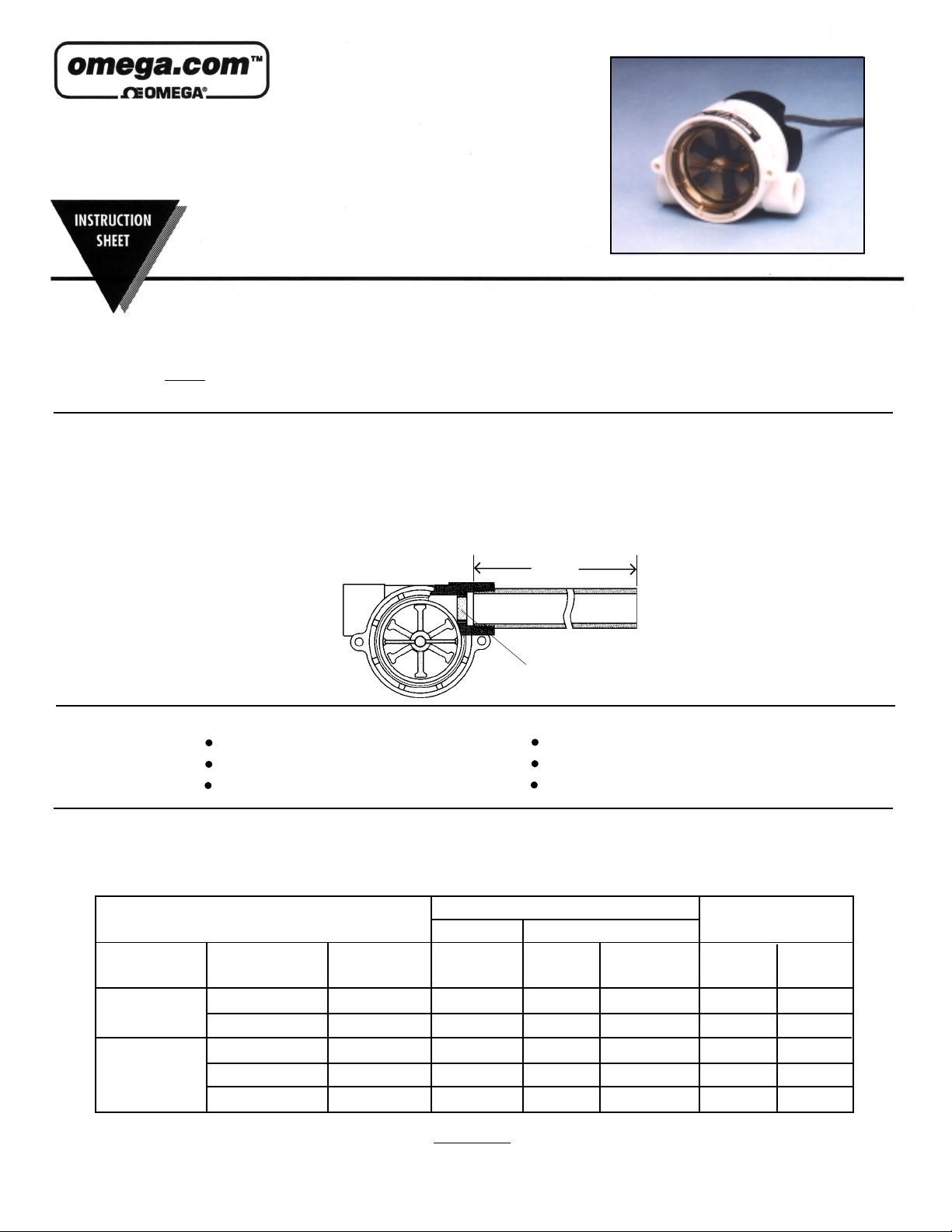
into most pulse input devices. The FPR130 units monitor dynamic fluid flow. The rotor reacts to turbulence, pulsation, entrained air, and other flow anomalies induced in the flow stream by other process hardware. For optimum performance, install
FPR130 units where nominal flow conditions exist, with ports located at the top. Incoming flow may be placed to either port. A
minimum of 8" of straight pipe on the inlet side is required.
NOTENOTE
NOTE: The carrier will not honor any claims unless all shipping material is saved for their examination.
NOTENOTE
8" Min.
à
Incoming
Flow
Low Flow
Adapter
ApplicationsApplications
Applications
ApplicationsApplications
Low Flow ApplicationsLow Flow Applications
Low Flow Applications
Low Flow ApplicationsLow Flow Applications
A low flow adapter is supplied with most FPR130 units. It is used to produce accurate response at low flow rates. Press-fit the
adapter as shown above, in the port selected for incoming flow.
BodyBody
Body
BodyBody
MaterialMaterial
Material
MaterialMaterial
PolypropylenePolypropylene
Polypropylene
PolypropylenePolypropylene
BrassBrass
Brass
BrassBrass
Water Purification/Dispensing Systems
Chemical Metering Equipment
Water Sampling
StandardStandard
Standard
StandardStandard
Port SizePort Size
Port Size
Port SizePort Size
NPTNPT
NPT
NPTNPT
.25"
.50"
.25"
.50"
.75"
Part Part
Part
Part Part
NumberNumber
Number
NumberNumber
FPR131
FPR132
FPR133
FPR134
FPR135
RangeRange
Range
RangeRange
0.5 - 5.0
4.0 - 20.0
0.5 - 5.0
4.0 - 20.0
3.0 - 30.0
Ice-Making Machinery
Water Injection Systems
Proof of Delivery Systems
See Flow Range chart below:See Flow Range chart below:
See Flow Range chart below:
See Flow Range chart below:See Flow Range chart below:
Flow Range - GPMFlow Range - GPM
Flow Range - GPM
Flow Range - GPMFlow Range - GPM
Low FlowLow Flow
Low Flow
Low FlowLow Flow
AdapterAdapter
Adapter
RangeRange
Range
RangeRange
0.1 - 1.0
1.5 - 12.0
0.1 - 1.0
1.5 - 12.0
N/A
AdapterAdapter
Part NumberPart Number
Part Number
Part NumberPart Number
152147
151832
152147
151832
N/A
K-FactorK-Factor
K-Factor
K-FactorK-Factor
(Pulses/Gal)(Pulses/Gal)
(Pulses/Gal)
(Pulses/Gal)(Pulses/Gal)
StandardStandard
Standard
StandardStandard
2196
611
1529
627
243
Low FlowLow Flow
Low Flow
Low FlowLow Flow
10,900
959
10,080
971
N/A
WW
ARNINGARNING
W
ARNING
WW
ARNINGARNING
When determining chemical compatibility of materials of construction, the flow media
and application-associated environmental conditions should be carefully considered.
Page 2
InstallationInstallation
Installation
InstallationInstallation
FPR130 sensors connect to piping via NPT mating thread forms. The following guidelines are provided to assist with
installation for a leak-free seal, without damage to the unit:
1) Apply pipe thread sealant to male pipe threads.
2) Thread FPR130 unit onto male pipe thread until hand-tight.
3) Tighten pipe 1 to 1-1/2 additional turns.
4) If improper seal results, continue turning pipe into unit in 1/4 turn increments.
Do not exceed one additional turn on plastic versions Do not exceed one additional turn on plastic versions
Do not exceed one additional turn on plastic versions.
Do not exceed one additional turn on plastic versions Do not exceed one additional turn on plastic versions
Recommended Pipe Sealants: T Recommended Pipe Sealants: T
Recommended Pipe Sealants: T
Recommended Pipe Sealants: T Recommended Pipe Sealants: T
Electrical DataElectrical Data
Electrical Data
Electrical DataElectrical Data
efloneflon
eflon
efloneflon
®®
®
®®
Thread T Thread T
Thread T
Thread T Thread T
ape.ape.
ape.
ape.ape.
Input power and output are connected via a multi-conductor, PVC-jacketed 24" cable. Color codes are shown below:
+Vdc - Power In
Power and Signal Ground
Signal Output - High
Red
Black
White
This is a PNP output. A 5-10 K !"pull-down resistor is needed between
black and white wires. For units without a pull-down resistor (such as the
DPF70 Series), the DPF700 meter does not require an external pull-down
resistor, since it can be set up for PNP output.
Panel MountingPanel Mounting
Panel Mounting
Panel MountingPanel Mounting
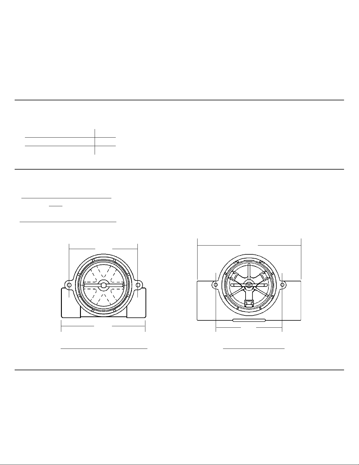
Any FPR130 sensor may be panel mounted using holes integrated into the bodies:
Plastic (Polypropylene) BodiesPlastic (Polypropylene) Bodies
Plastic (Polypropylene) Bodies: Two (2) mounting ears are provided at the body centerline to receive #8 self-tapping
Plastic (Polypropylene) BodiesPlastic (Polypropylene) Bodies
NoteNote
screws.
: :
Note
: ANSI T Type 23 self-tapping screws are recommended. They may be replaced with standard machine
NoteNote
: :
screws if reinstallation should be required.
Brass and Stainless Steel BodiesBrass and Stainless Steel Bodies
Brass and Stainless Steel Bodies: Two (2) mounting holes are provided on the body centerline, as shown below.
Brass and Stainless Steel BodiesBrass and Stainless Steel Bodies
#8-32UNC-2B screws are required for mounting.
2.50"
3.94"
Plastic. Brass, Stainless SteelPlastic. Brass, Stainless Steel
Plastic. Brass, Stainless Steel
Plastic. Brass, Stainless SteelPlastic. Brass, Stainless Steel
1/4", 1/2", 9/16"-18
Accuracy/CalibrationAccuracy/Calibration
Accuracy/Calibration
Accuracy/CalibrationAccuracy/Calibration
3.06"
Brass/Stainless SteelBrass/Stainless Steel
Brass/Stainless Steel
Brass/Stainless SteelBrass/Stainless Steel
2.5"
3/4" & 1"
The accuracy of the FPR130 Series pulse output flow sensors is ±15% of full scale flow rate for the 4 to 20 GPM and 6
to 30 GPM ranges. All other ranges have an accuracy of ±7% of full scale flow rate. Improved accuracy can be
achieved by calibrating the individual flow sensor by counting the number of pulses generated as a known volume of
liquid passes through the sensor. Pulses generated, divided by gallons of water collected during the test, equals the
specific K-factor for your FPR130 sensor. Nominal K-factors are given in the flow range chart on page 1 of this instruction sheet.
Page 3

Signal OutputSignal Output
Signal Output
Signal OutputSignal Output
Output signal for the FPR130 series is an on/off pulse of the DC voltage supplied to the unit. It is compatible with
most pulse input devices.
the flow rate and ranges from approximately 25 Hz at low flow to 225 Hz at high flow.
Input voltage rangeInput voltage range
Input voltage range is 4.5 to 24 VDC. Frequency of the output pulse is proportional to
Input voltage rangeInput voltage range
See example below:See example below:
See example below:
See example below:See example below:
Low FlowLow Flow
Low Flow
Low FlowLow Flow
12
0
Filtration and CleaningFiltration and Cleaning
Filtration and Cleaning
Filtration and CleaningFiltration and Cleaning
150 micron filtration is recommended. However, should foreign particles enter the FPR130 sensor, accumulation is easily
cleared by removing the lens from the body. The lens is removed by turning its center rib 45° counter-clockwise and then
pulling it out. To reinstall the lens, simply reverse the process. Pressure must be relieved from the system prior to sensor
clean-out.
SpecificationsSpecifications
Specifications
SpecificationsSpecifications
WW
etted Materialsetted Materials
W
etted Materials
WW
etted Materialsetted Materials
Body:
Rotor Pin:
Rotor:
Lens:
O-Ring:
Operating Pressure, Max.Operating Pressure, Max.
Operating Pressure, Max.
Operating Pressure, Max.Operating Pressure, Max.
Brass Body
Polypropylene Body
Operating TOperating T
Operating T
Operating TOperating T
Brass Body
Polypropylene Body
Electronics (Both Bodies)
Viscosity, Max.
Input Power
Output Signal
Max. Current Source Output
Frequency Output Range
Electrical Termination
emperature, Max.emperature, Max.
emperature, Max.
emperature, Max.emperature, Max.
TIME
A Repair Kit is available, including the following replacement parts:A Repair Kit is available, including the following replacement parts:
A Repair Kit is available, including the following replacement parts:
A Repair Kit is available, including the following replacement parts:A Repair Kit is available, including the following replacement parts:
lens, O-ring, shaft, and rotorlens, O-ring, shaft, and rotor
lens, O-ring, shaft, and rotor
lens, O-ring, shaft, and rotorlens, O-ring, shaft, and rotor
Brass or Polypropylene (Hydrolytically Stable, Glass-Reinforced)
Ceramic
PPS/Teflon Composite; Black
Polysulfone
Buna N or Viton
200 PSIG at 70°F
100 PSIG at 70°F
212°F (82.2°C)
180°F (82.2°C)
150°F (65.5°C) - Ambient
200 SSU
4.5 to 24 Vdc
4.5 to 24 VDC Pulse. Pulse rate dependent on flow rate, port size, and range
50mA (Max)
25 Hz Low Flow to 225 Hz High Flow
22 AWG PVC-Jacketed, 24" Cable
Color Coded: Red = +VDC, Black = Ground, White = Signal Output
+VDC
. Consult Sales Department.. Consult Sales Department.
. Consult Sales Department.
. Consult Sales Department.. Consult Sales Department.
High FlowHigh Flow
High Flow
High FlowHigh Flow
12
0
TIME
††
†
††
+VDC
†
Hydrolytically stable, glass-reinforced, Polypropylene is
UL-recognized to UL746B at a relative temperature index of 65°C
Page 4

Important Points!Important Points!
Important Points!
Important Points!Important Points!
Product must be maintained and installed in strict accordance with the National Electrical Code and this
instruction bulletin. Failure to observe this warning could result in serious injuries or damages.
Do not use in hazardous area applications.
The pressure and temperature limitations in this instruction bulletin must not be exceeded. These
pressures and temperatures take into consideration possible system surge pressures/temperatures and
their frequencies.
Selection of materials for compatibility with the media is critical to the life and operation of these units. Take
care in the proper selection of materials of construction, particularly wetted materials.
Life expectancy of switch contacts varies with applications. Contact Omega's Flow Deprtment if life cycle
testing is required.
Physical damage sustained by the product may render it unserviceable.
 Loading...