

Page 1
FPD1004 thru FPD1007,
FPD1034, FPD1105, FPD1204
and FPD1205
(includes -R Option)
SERIES HIGH FLOW
Positive Displacement Flowmeters
Page 2

Page 3

TABLE OF CONTENTS
Important Information ................................. 2
Installation .................................................. 2
Operation .................................................... 3
Electrical Connections ................................ 4
Service Instructions .................................... 5
Troubleshooting .......................................... 6
FPD1004 Aluminum Meter
Parts List ...............................................
FPD1204 Aluminum Meter
Parts List ...............................................
FPD1034 Aluminum Meter
Parts List ...............................................
FPD1105 PPS Meter
Parts List .............................................
FPD1005 Aluminum Meter
Parts List .............................................
FPD1205 Stainless Steel Meter
Parts List .............................................
FPD1006 Aluminum Meter
Parts List .............................................
FPD1007 Aluminum Meter
Parts List .............................................
7
7
9
11
13
13
15
17
To the owner:
Thank you for purchasing an OMEGA FPD
Series Flowmeter. Please take a few minutes to read through the manual before
installing and operating your meter. If you
have any problems with the meter, refer to
the Maintenance and Troubleshooting sections of the manual.
This manual contains connection and operating instructions for the OMEGA FPD
Series meters with pulse outputs. This includes the following models:
FPD1004 FPD1005
FPD1204 FPD1205
FPD1034 FPD1006
FPD1105 FPD1007
Part breakdowns for each model are located at the back of this manual. For models
with displays and/or 4-20 mA output, an
additional instruction manual is provided.
The OMEGA FPD Series flowmeter has
incorporated the oval rotor principal into its
design. This has proven to be a reliable and
highly accurate method of measuring flow.
Exceptional repeatability and high accuracy
over a wide range of fluid viscosities and
flowrates are features of the OMEGA FPD
Series flowmeter design. The low pressure
drop and high pressure rating, means the
OMEGA FPD Series flowmeters are suitable for both gravity and pump (in-line)
applications.
1
Page 4
IMPORTANT INFORMATION INSTALLATION
Please read this information
!
▲
carefully before use!
Before use, confirm the fluid to be used is
compatible with the meter or consult with
OMEGA for advice.
To prevent damage from dirt or foreign
matter, OMEGA recommends a Y or basket type 60 mesh strainer be installed as
close as possible to the inlet side of the
meter. (If required, contact OMEGA for further information.)
NOTE: When a strainer is installed it should
be regularly inspected and cleaned.
Failure to keep the strainer clean will
dramatically effect flowmeter performance.
To prevent damage to the meter, slowly fill
the system with fluid. This will prevent damage caused by air purge.
NOTE: Failure to do this could damage the
meter.
Maintenance can be performed on the liquid crystal display and pulse units without removing or isolating the meter from
the line. When maintenance to any other
part of the meter is required, the meter must
be isolated and the line pressure reduced.
The Reed Switch pulse unit can cause inaccurate rate counts when used with high
speed counters. It is advised that a debounce circuit be used or alternatively use
the Hall Effect sensor option.
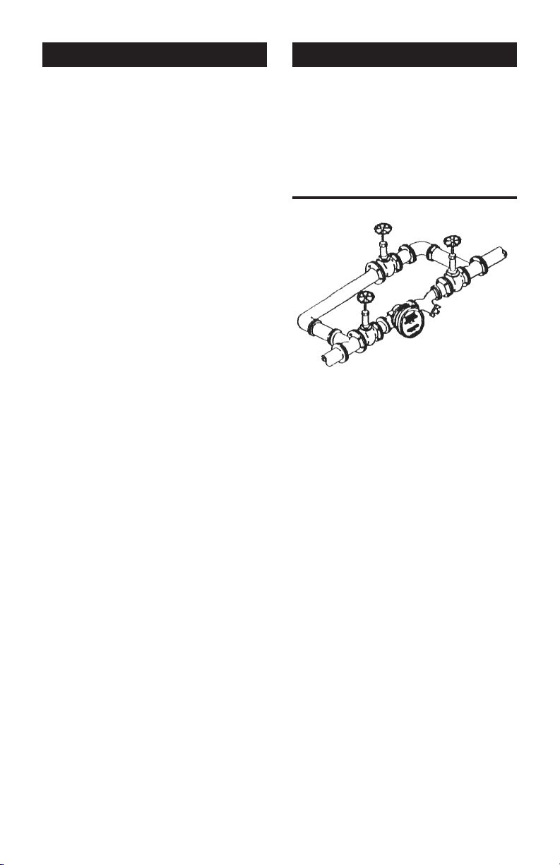
1. OMEGA recommends that when set
ting up pipework for meter installations,
a bypass line be included in the de-
sign. This provides the ability for a
meter to be removed for maintenance
without interrupting production. (See
Figure 1)
Figure 1
Bypass Line
Flow Outlet
2. Use thread sealant on all pipe threads.
3. For pump applications, ensure pipe
work has the appropriate working pressure rating to match the pressure output of the pump.
4. Install a wire mesh strainer (Y or bas-
ket type 60 mesh) as close as possible
to the inlet side of the meter.
5. Ensure that the meter is installed so
that the flow of the liquid is in the direction of the arrows embossed on the
meter body.
6. The meter can be installed in any orien
tation as long as the meter shafts are in
a horizontal plane. (See Figure 2) The
register assembly may be oriented to
suit the individual installation.
Flow Inlet
Strainer
-
-
2
Page 5
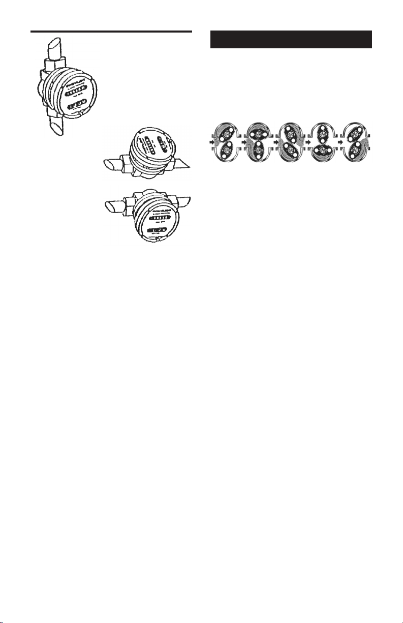
➧
R I G H T
Figure 2
OPERATION
When fluid passes through the meter, the
rotors turn. The magnets which are located
in the rotors will pass across the pulser
circuit board (containing either Reed Switch
or Hall Effect sensors).
W R O N G
R I G H T
NOTE: Incorrect installation can cause pre-
mature wear of meter components
7. Do not overtighten meter connections.
8. It is important that after initial installa
tion you fill the line slowly, high speed
air purge could cause damage to the
rotors.
9. Test the system for leaks.
10. Check the strainer for swarf or foreign
material. After the first 200 liters, check
periodically – particularly if the flowrate
decreases.
➧
➧
A signal is received which is then sent by
the Pulse Circuit Board (PCB) to the relevant LC display or receiving instrument.
-
3
Page 6
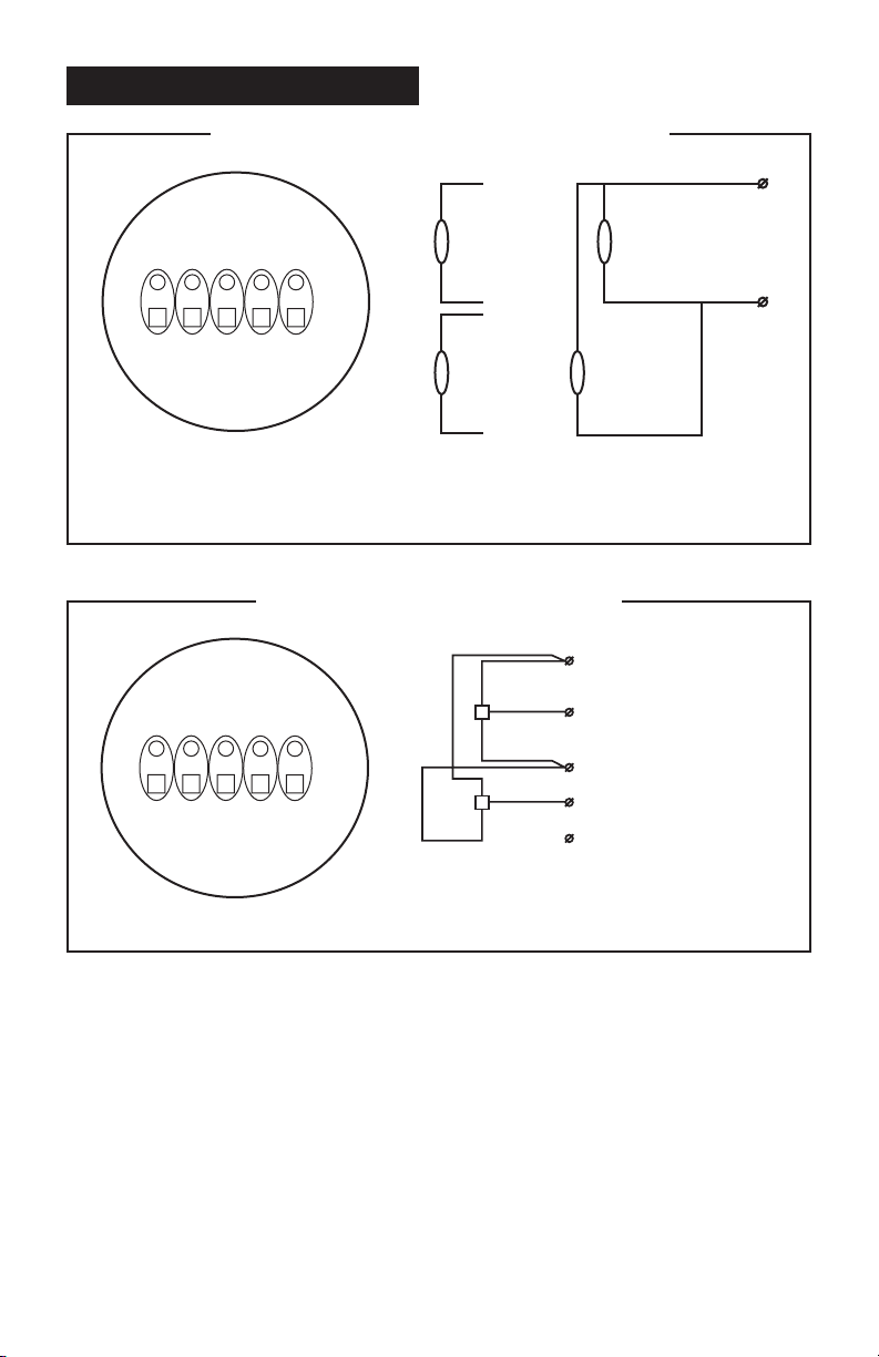
ELECTRICAL CONNECTIONS
1 2 3
4 5
Ground
1
2
3
4
1
2
3
4
1 2 3
4 5
1
2
3
4
5
Figure 3: Reed Switch Connections for PCB Terminals
Contact Rating 15 VA
Maximum Voltage 150 VDC
Figure 4: Hall Effect Sensor Connections
Configuration 1
2 x Pulse Outputs
Double Pulse Output
Hall Effect Voltage 4.5 to 24 VDC
Current Draw Minimum 4.6 mA
Output NPN Open Collector 25 mA
Configuration 2
Link 2 & 3 for
1 – HE Supply +
2 – HE 1 Signal
3 – HE Common –
4 – HE 2 Signal
5 – HE Ground
4
Page 7

SERVICE INSTRUCTIONS
Disassembly:
Ensure that the fluid supply to the meter is
disconnected, and the line pressure is released before disassembly. This step
is not required if you need to repair or
perform maintenance on the display or
PCB. In this case, there is no need to
isolate the meter from the flow. Refer to
the exploded parts diagram for your meter.
Units with Pulse Caps – Undo the con-
1.
duit connector, remove pulse cap and
remove the wires from the pulse terminal board.
Standard LC Display – Unscrew the four
large screws on top of the LC Display.
Carefully separate the LC Display from
the plastic housing and disconnect the
wires from the pulse terminal block.
2. Loosen the four cap screws and nuts
that hold down the meter cap. Remove
the screws and nuts and lift off the cap.
3. Remove the O-ring from the O-ring
groove in the meter cap.
4. Remove rotors.
Reassembly:
1. Before reassembling, check the condition of the rotors. Replace if necessary.
2. Rotors must be replaced in the proper
orientation (see list that follows). There
is no difference between rotor one or
rotor two.
1/2 in. Meters:
FPD1004 – Plugs Down
FPD1204 – Plugs Down
3/4 in. Meters:
FPD1034 – Plugs Up
1 in. Meters:
FPD1005 – Plugs Up
FPD1105 – Plugs Down
FPD1205 – Plugs Up
1-1/2 in. Meters:
FPD1006 – Plugs Up
2 in. Meters:
FPD1007 – Plugs Up
Figure 5
Rotor #1
Rotor #2
Rotors must be at 90° to each other
3. Replace the rotors onto the shafts at 90
degrees to each other. (See Figure 5)
Check their operation by turning either
of the rotors. If the rotors are not in mesh
correctly or do not move freely, remove
one of the rotors and replace correctly
at 90 degrees to the other rotor. Recheck the operation of the rotors.
4. Replace the O-ring back into the groove
in the meter cap. If the O-ring has grown
or is damaged in any way, replace it with
a new one.
5. Replace the meter cap. Insert the cap
head screws and fix nuts and tighten
in the sequence 1, 3, 2 and 4. Torque
screws to the appropriate pressure per
the chart that follows:
Body Screw
Material Torque
1/2 in. Meters:
FPD1004 Aluminum 31 in./lbs.
FPD1204 S.S. 80 in./lbs.
3/4 in. Meters:
FPD1034 Aluminum 31 in./lbs.
1 in. Meters:
FPD1005 Aluminum 31 in./lbs.
FPD1105 PPS 80 in./lbs.
FPD1205 S.S. 80 in./lbs.
1-1/2 in. Meters:
FPD1006 Aluminum 75 in./lbs.
2 in. Meters:
FPD1007 Aluminum 150 in./lbs.
6. The replacement of cables and connectors are a reversal of the disassembly
procedure. Replace conduit fitting if re-
quired.
5
Page 8

7. Test the meter by turning the rotors with
a finger or by applying very low air pres
sure (a good breath) to one end of the
meter, before returning the meter to the
line.
Pulse Circuit Board (PCB) Notes:
The PCB board is fastened to the meter
cap by two screws and stand off’s. All care
and caution should be taken when removing or handling the PCB as both the Reed
Switch and Hall Effect sensors are fragile.
Individual Reed Switches or Hall Effect sensors are not available as replacement parts
and are only available with the PCB.
TROUBLESHOOTING
Symptom Probable Cause Corrective Action
FLUID WILL NOT 1. Foreign matter blocking Dismantle meter, clean rotors. Strainer must
FLOW THROUGH rotors be fitted in-line.
THE METER
2. Line strainer blocked Clean strainer.
3. Damaged rotors Replace rotors. Strainer must be fitted in-line.
4. Meter connections over- Re-adjust connections.
tightened
5. Fluid is too viscous See specifications for rated viscosity.
REDUCED FLOW 1. Line strainer partially Clean strainer.
THROUGH THE blocked
METER
2. Fluid is too viscous See specifications for rated viscosity.
METER READING 1. Fluid flowrate is too low See specifications for flow range.
INACCURATE or too high
2. Fluid is too viscous See specifications for rated viscosity.
3. Excess wear caused by Check meter body and rotors. Replace as
incorrect installation required.
METER NOT 1. Faulty Hall Effect sensor Replace PCB Board.
GIVING A PULSE
SIGNAL 2. Faulty Reed Switch Replace PCB Board.
3. Magnets failed Replace rotors.
6
Page 9

METER PARTS LISTING
Models: FPD1004 - Aluminum
FPD1204 - Stainless Steel
1
2
3
4
5
6
7
8
9
u = Recommended Spare
Parts to stock.
Bold Text = Indicates Stainless Steel
model parts.
Item Rec. Part or Set
No. Qty. Parts
1 1 MS298N Meter Body 1/2 in. NPT (Aluminum)
1 1 MS337N Meter Body 1/2 in. NPT (Stainless Steel)
2 1 u BS145TE O-Ring (PTFE)
2 1 u BS145V O-Ring (Fluorocarbon)
3 2 u MS342S Rotors PPS (Polyphenylene Sulfide Resins)
3 2 u MS342HS High Viscosity Rotors (PPS)
4 1 MS297 Meter Cap (Aluminum)
4 1 MS338 Meter Cap (Stainless Steel)
5 1 u MS344-R PCB (Standard Reed Switch)
5 1 u MS344-HE PCB (Hall Effect Sensor)
6 2 MS284S PCB Board Screws
7 4 u MS346S Meter Cap Screws (Standard)
7 4 u MS350S Meter Cap Screws (Stainless Steel)
8 1 u MS340S Pulser Cap Gasket
9 1 MS296 Pulser Cap (Aluminum) 20mm Conduit Thread
9 1 MS296N Pulser Cap (Aluminum) 1/2 in. NPT Thread
9 1 MS339 Pulser Cap (S/Steel) 20mm Conduit Thread
9 1 MS339N Pulser Cap (S/Steel) 1/2 in. NPT Thread
10 2 MS347S Pulser Cap Screw (Stainless Steel)
(Order from this column only) Part Description
10
7
Page 10

SPECIFICATIONS
FPD1004 & FPD1204
Flow Ranges (LPM or GPM)
Above 5 centipoise
Below 5 centipoise
Accuracy of Reading
Maximum Viscosity* 1000 Centipoise
Maximum Operating Pressure
Maximum Operating Temperature
Pulse Type
Pulses per Liter/Gallon
Single Sensor (K-factor)
1 to 30 / 0.26 to 8
3 to 25 / 0.8 to 6.60
± 0.5%
5500 kPa / 800 PSI / 55 Bar
80°C / 176°F (Stainless Steel 120°C / 248°F)
Reed Switch Sensor or Hall Effect Sensor
112 PPL / 424 PPG
* Unless High Viscosity Rotors are fitted.
DIMENSIONS
8
Page 11

METER PARTS LISTING
Model: FPD1034 - Aluminum
1
2
3
4
5
6
u = Recommended Spare
Parts to stock.
Bold Text = Indicates Stainless Steel
model parts.
Item Rec. Part or Set
No. Qty. Parts
1 1 MS779NS Meter Body 3/4 in. NPT (Aluminum)
2 1 u BS235TE O-Ring (PTFE)
2 1 u BS235V O-Ring (Fluorocarbon)
3 2 u MS370S Rotors (PPS) (Polyphenylene Sulfide Resins)
4 1 MS150 Meter Cap (Aluminum)
5 1 u MS28-R PCB (Standard Reed Switch)
5 1 u MS28-HE PCB (Hall Effect Sensor)
6 4 MS111S PCB Board Screws
7 6 u MS114S Meter Cap Screws (Standard)
8 1 u MS300 Pulser Cap Gasket
9 1 MS160 Pulser Cap (Aluminum) 20mm Conduit Thread
9 1 MS160N Pulser Cap (Aluminum) 1/2 in. NPT Thread
10 4 MS115S Pulser Cap Screw (Stainless Steel)
(Order from this column only) Part Description
7
8
9
10
9
Page 12

SPECIFICATIONS
FPD1034
Flow Ranges (LPM or GPM)
Above 5 centipoise
Below 5 centipoise
Accuracy of Reading
Maximum Viscosity
Maximum Operating Pressure
Minimum Operating Temperature
Maximum Operating Temperature
Pulse Type
Pulses per Liter/Gallon
Single Sensor (K-factor)
3 to 60 / 0.8 to 15.85
8 to 53 / 2.1 to 14
± 0.5%
1000 Centipoise
5500 kPa / 800 PSI / 55 Bar
-10°C (+14°F)
+80°C (+176°F)
Reed Switch Sensor or Hall Effect Sensor
52 PPL / 197 PPG
DIMENSIONS
126mm
10
133mm
86mm
112mm
18mm
21.5mm
Page 13

METER PARTS LISTING
1
2
3
Model: FPD1105 - PPS
4
5
6
7
8
9
10
u = Recommended Spare
Parts to stock.
Bold Text = Indicates Stainless Steel
model parts.
Item Rec. Part or Set
No. Qty. Parts
1 1 MS352N Meter Body 1 in. NPT (PPS) & Hastalloy C Shafts
2 1 u BS235TE O-Ring (PTFE)
2 1 u BS235V O-Ring (Fluorocarbon)
3 2 u MS370S Rotors (PPS)
4 1 MS405R Meter Cap (PPS)
5 1 u MS368-R PCB (Standard Reed Switch)
5 1 u MS344-HE PCB (Hall Effect Sensor)
6 2 MS284S PCB Board Screws
7 4 u MS350S Meter Cap Screws (Stainless Steel)
8 1 u MS340S Pulser Cap Gasket
9 1 MS406R Pulser Cap (PPS) 16mm Conduit Thread
9 1 MS406R-N Pulser Cap (PPS) 1/2 in. NPT Thread
10 2 MS347S Pulser Cap Screw (Stainless Steel)
33 1 MS111S Earthing Screw
34 4 MS497S Nut (S/Steel) - not shown, recessed in body
(Order from this column only) Part Description
33
11
Page 14

SPECIFICATIONS
FPD1105
Flow Ranges (LPM or GPM)
Above 5 centipoise
Below 5 centipoise
Accuracy of Reading
Maximum Viscosity
Maximum Operating Pressure
Maximum Operating Temperature
Pulse Type
Pulses per Liter/Gallon
Single Sensor (K-factor)
3 to 80 / 0.8 to 21
8 to 70 / 2 to 18.5
± 0.5%
1000 Centipoise
1000 kPa / 150 PSI / 10 Bar
80°C / 176°F
Reed Switch Sensor or Hall Effect Sensor
52 PPL / 197 PPG
DIMENSIONS
12
Page 15

METER PARTS LISTING
Models: FPD1005 - Aluminum
FPD1205 - Stainless Steel
1
2
3
4
5
6
u = Recommended Spare
Parts to stock.
Bold Text = Indicates Stainless Steel
model parts.
Item Rec. Part or Set
No. Qty. Parts
1 1 MS187N Meter Body 1 in. NPT (Aluminum)
1 1 MS185N Meter Body 1 in. NPT (Stainless Steel)
1 1 MS187F Meter Body 1 in. ANSI 150 lb. Flange (Aluminum)
1 1 MS185F Meter Body 1 in. ANSI 150 lb. Flange (S/Steel)
1 1 MS185T Meter Body 1 in. Tri-Clover
2 1 u BS235TE O-Ring (PTFE)
2 1 u BS235V O-Ring (Fluorocarbon)
3 2 u MS50-1S Rotors (Stainless Steel)
3 2 u MS50-1HS High Viscosity Rotors (Stainless Steel)
4 1 MS150 Meter Cap (Aluminum)
4 1 MS250 Meter Cap (Stainless Steel)
5 1 u MS28-R PCB (Standard Reed Switch)
5 1 u MS28-HE PCB (Hall Effect Sensor)
6 4 MS111S PCB Board Screws
7 6 u MS114S Meter Cap Screws (Standard)
7 6 u MS200S Meter Cap Screws (Stainless Steel)
8 1 u MS300 Pulser Cap Gasket
9 1 MS160 Pulser Cap (Aluminum) 20mm Conduit Thread
9 1 MS160N Pulser Cap (Aluminum) 1/2 in. NPT Thread
9 1 MS170 Pulser Cap (S/Steel) 20mm Conduit Thread
10 4 MS115S Pulser Cap Screw (Stainless Steel)
(Order from this column only) Part Description
7
®
Flange (S/Steel)
8
9
10
13
Page 16

SPECIFICATIONS
FPD1005 & FDP1205
Flow Ranges (LPM or GPM)
Above 5 centipoise
Below 5 centipoise
Accuracy of Reading
Maximum Viscosity* 1000 Centipoise
Maximum Operating Pressure
Maximum Operating Temperature
Pulse Type
Pulses per Liter/Gallon
Single Sensor (K-factor)
Double Sensor (K-factor)
6 to 120 / 1.6 to 32
10 to 100 / 2.6 to 26
± 0.5%
NPT – 5500 kPa / 800 PSI / 55 Bar or Flange Rule
80°C / 176°F (Stainless Steel 120°C / 248°F)
Reed Switch Sensor or Hall Effect Sensor
36 PPL / 136.3 PPG
72 PPL / 272.6 PPG
* Unless High Viscosity Rotors are fitted.
DIMENSIONS
14
Page 17

METER PARTS LISTING
Model: FPD1006 - Aluminum
1
2
3
4
5
6
u = Recommended Spare
Parts to stock.
Bold Text = Indicates Stainless Steel
model parts.
Item Rec. Part or Set
No. Qty. Parts
1 1 MS191N Meter Body 1-1/2 in. NPT (Aluminum)
1 1 MS191F Meter Body 1-1/2 in. ANSI 150 lb. Flange (Alum.)
2 1 u BS243TE O-Ring (PTFE)
2 1 u BS243V O-Ring (Fluorocarbon)
3 2 u MS58S Rotors (PPS)
3 2 u MS58HS High Viscosity Rotors (PPS)
4 1 MS220 Meter Cap (Aluminum)
5 1 u MS201-R PCB (Standard Reed Switch)
5 1 u MS201-HE PCB (Hall Effect Sensor)
6 4 MS284S PCB Board Screws
7 6 u MS116S Meter Cap Screws (Standard)
8 1 u MS300 Pulser Cap Gasket
9 1 MS160 Pulser Cap (Aluminum) 20mm Conduit Thread
9 1 MS160N Pulser Cap (Aluminum) 1/2 in. NPT Thread
10 4 MS115S Pulser Cap Screw (Stainless Steel)
(Order from this column only) Part Description
7
8
9
10
15
Page 18

SPECIFICATIONS
FPD1006
Flow Ranges (LPM or GPM)
Above 5 centipoise
Below 5 centipoise
Accuracy of Reading
Maximum Viscosity* 1000 Centipoise
Maximum Operating Pressure** NPT – 5500 kPa / 800 PSI / 55 Bar
Maximum Operating Temperature
-10°C to 120°C (14°F to 248°F) (Stainless Steel)
Pulse Type
Pulses per Liter/Gallon
Single Sensor (K-factor)
Double Sensor (K-factor)
10 to 250 / 2.6 to 66
15 to 235 / 4 to 62
± 0.5%
-10°C to 80°C (14°F to 176°F) (Aluminum)
Reed Switch Sensor or Hall Effect Sensor
14.5 PPL / 54.9 PPG
29 PPL / 109.8 PPG
* Unless High Viscosity Rotors are fitted.
** Meter conforms to PED 97/23/EC CAT 1.
DIMENSIONS
16
Page 19

METER PARTS LISTING
Model: FPD1007 - Aluminum
1
2
3
4
5
6
u = Recommended Spare
Parts to stock.
Bold Text = Indicates Stainless Steel
model parts.
Item Rec. Part or Set
No. Qty. Parts
1 1 MS283F Meter Body 2 in. ANSI 150 lb. Flange (Alum.)
1 1 MS283N Meter Body 2 in. NPT (Aluminum)
2 1 u BS252TE O-Ring (PTFE)
2 1 u BS252V O-Ring (Fluorocarbon)
3 2 u MS147S Rotors (PPS)
3 2 u MS147HS High Viscosity Rotors (PPS)
4 1 MS230 Meter Cap (Aluminum)
5 1 u MS201-R PCB (Standard Reed Switch)
5 1 u MS201-HE PCB (Hall Effect Sensor)
6 4 MS284S PCB Board Screws
7 6 u MS243S Meter Cap Screws (Standard)
8 1 u MS300 Pulser Cap Gasket
9 1 MS160 Pulser Cap (Aluminum) 20mm Conduit Thread
9 1 MS160N Pulser Cap (Aluminum) 1/2 in. NPT Thread
10 4 MS115S Pulser Cap Screw (Stainless Steel)
(Order from this column only) Part Description
7
8
9
1
0
17
Page 20

SPECIFICATIONS
FPD1007
Flow Ranges (LPM or GPM)
Above 5 centipoise
Below 5 centipoise
Accuracy of Reading
Maximum Viscosity* 1000 Centipoise
Maximum Operating Pressure** NPT – 5500 kPa / 800 PSI / 55 Bar or Flange Rule
Maximum Operating Temperature
-10°C to 120°C (14°F to 248°F) (Stainless Steel)
Pulse Type
Pulses per Liter/Gallon
Single Sensor (K-factor)
Double Sensor (K-factor)
15 to 350 / 4 to 92
33 to 300 / 9 to 79
± 0.5%
-10°C to 80°C (14°F to 176°F) (Aluminum)
Reed Switch Sensor or Hall Effect Sensor
6.68 PPL / 25.3 PPG
13.4 PPL / 50.6 PPG
* Unless High Viscosity Rotors are fitted.
** Meter conforms to PED 97/23/EC CAT 1.
DIMENSIONS
18
Page 21

Page 22

Page 23

Page 24

M-4 102 / 0608
 Loading...