

Page 1
Where Do I Find Everything I Need for
Process Measurement and Control?
OMEGA…Of Course!
Shop online at omega.com
TEMPERATURE
䡺⻬
Thermocouple, RTD & Thermistor Probes, Connectors, Panels & Assemblies
䡺⻬
Wire: Thermocouple, RTD & Thermistor
䡺⻬
Calibrators & Ice Point References
䡺⻬
Recorders, Controllers & Process Monitors
䡺⻬
Infrared Pyrometers
PRESSURE, STRAIN AND FORCE
䡺⻬
Transducers & Strain Gages
䡺⻬
Load Cells & Pressure Gages
䡺⻬
Displacement Transducers
䡺⻬
Instrumentation & Accessories
FLOW/LEVEL
䡺⻬
Rotameters, Gas Mass Flowmeters & Flow Computers
䡺⻬
Air Velocity Indicators
䡺⻬
Turbine/Paddlewheel Systems
䡺⻬
Totalizers & Batch Controllers
pH/CONDUCTIVITY
䡺⻬
pH Electrodes, Testers & Accessories
䡺⻬
Benchtop/Laboratory Meters
䡺⻬
Controllers, Calibrators, Simulators & Pumps
䡺⻬
Industrial pH & Conductivity Equipment
DATA ACQUISITION
䡺⻬
Data Acquisition & Engineering Software
䡺⻬
Communications-Based Acquisition Systems
䡺⻬
Plug-in Cards for Apple, IBM & Compatibles
䡺⻬
Datalogging Systems
䡺⻬
Recorders, Printers & Plotters
HEATERS
䡺⻬
Heating Cable
䡺⻬
Cartridge & Strip Heaters
䡺⻬
Immersion & Band Heaters
䡺⻬
Flexible Heaters
䡺⻬
Laboratory Heaters
ENVIRONMENTAL
MONITORING AND CONTROL
䡺⻬
Metering & Control Instrumentation
䡺⻬
Refractometers
䡺⻬
Pumps & Tubing
䡺⻬
Air, Soil & Water Monitors
䡺⻬
Industrial Water & Wastewater Treatment
䡺⻬
pH, Conductivity & Dissolved Oxygen Instruments
omega.com
e-mail: info@omega.com
For latest product manuals:
omegamanual.info
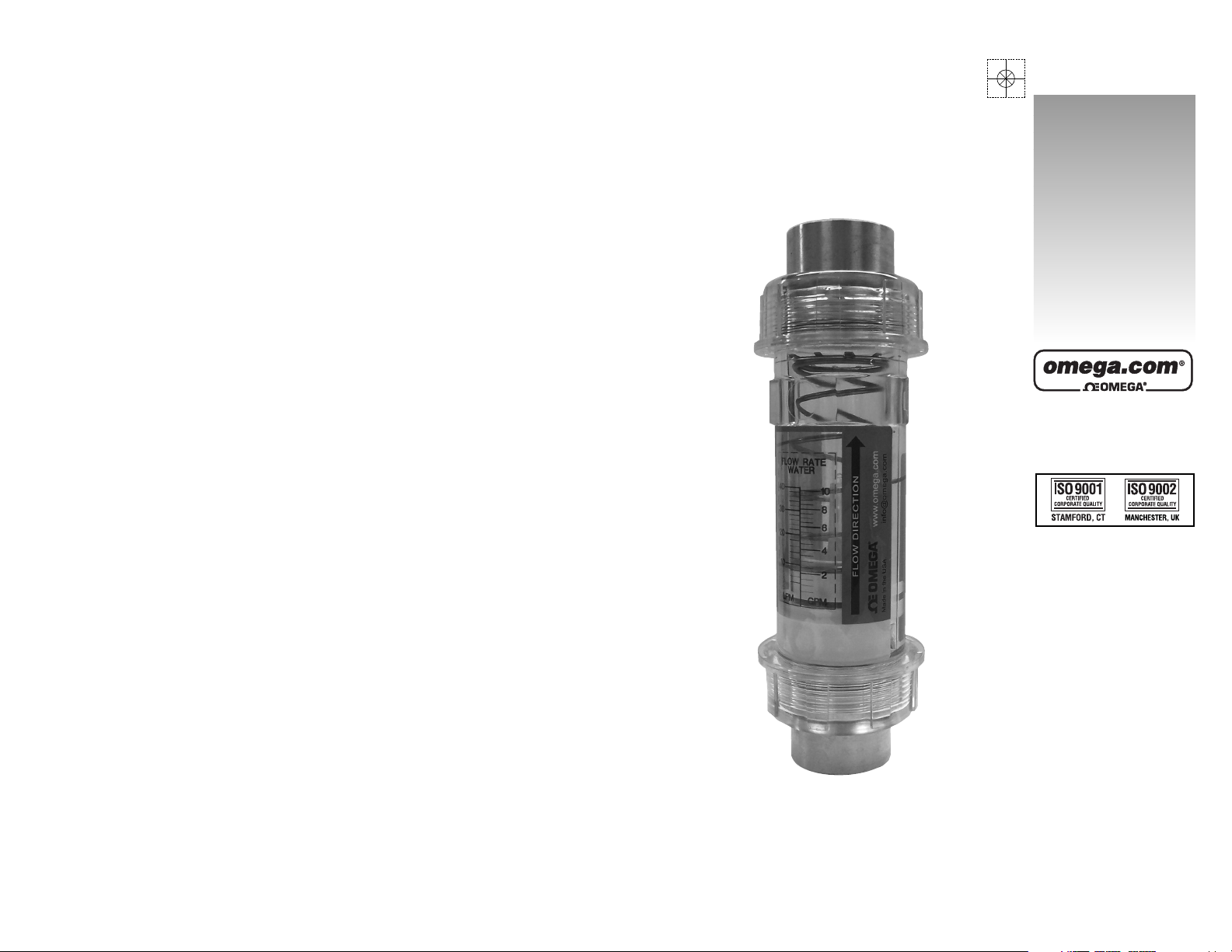
User’s Guide
FLC Series
Clear In-Line Flowmeters
M-4402/1207
Shop online at
Page 2
WARRANTY/DISCLAIMER
OMEGA ENGINEERING, INC. warrants this unit to be free of defects in materials and
workmanship for a period of 13 months from date of purchase. OMEGA’s WARRANTY adds
an additional one (1) month grace period to the normal one (1) year product warranty to
cover handling and shipping time. This ensures that OMEGA’s customers receive maximum
coverage on each product.
If the unit malfunctions, it must be returned to the factory for evaluation. OMEGA’s Customer
Service Department will issue an Authorized Return (AR) number immediately upon phone or
written request. Upon examination by OMEGA, if the unit is found to be defective, it will be
repaired or replaced at no charge. OMEGA’s WARRANTY does not apply to defects resulting
from any action of the purchaser, including but not limited to mishandling, improper
interfacing, operation outside of design limits, improper repair, or unauthorized modification.
This WARRANTY is VOID if the unit shows evidence of having been tampered with or shows
evidence of having been damaged as a result of excessive corrosion; or current, heat, moisture
or vibration; improper specification; misapplication; misuse or other operating conditions
outside of OMEGA’s control. Components in which wear is not warranted, include but are not
limited to contact points, fuses, and triacs.
OMEGA is pleased to offer suggestions on the use of its various products. However,
OMEGA neither assumes responsibility for any omissions or errors nor assumes
liability for any damages that result from the use of its products in accordance with
information provided by OMEGA, either verbal or written. OMEGA warrants only
that the parts manufactured by the company will be as specified and free of
defects. OMEGA MAKES NO OTHER WARRANTIES OR REPRESENTATIONS OF ANY
KIND WHATSOEVER, EXPRESSED OR IMPLIED, EXCEPT THAT OF TITLE, AND ALL
IMPLIED WARRANTIES INCLUDING ANY WARRANTY OF MERCHANTABILITY AND
FITNESS FOR A PARTICULAR PURPOSE ARE HEREBY DISCLAIMED. LIMITATION OF
LIABILITY: The remedies of purchaser set forth herein are exclusive, and the total
liability of OMEGA with respect to this order, whether based on contract, warranty,
negligence, indemnification, strict liability or otherwise, shall not exceed the
purchase price of the component upon which liability is based. In no event shall
OMEGA be liable for consequential, incidental or special damages.
CONDITIONS: Equipment sold by OMEGA is not intended to be used, nor shall it be used: (1)
as a “Basic Component” under 10 CFR 21 (NRC), used in or with any nuclear installation or
activity; or (2) in medical applications or used on humans. Should any Product(s) be used in or
with any nuclear installation or activity, medical application, used on humans, or misused in
any way, OMEGA assumes no responsibility as set forth in our basic WARRANTY/ DISCLAIMER
language, and, additionally, purchaser will indemnify OMEGA and hold OMEGA harmless from
any liability or damage whatsoever arising out of the use of the Product(s) in such a manner.
RETURN REQUESTS/INQUIRIES
Direct all warranty and repair requests/inquiries to the OMEGA Customer Service Department.
BEFORE RETURNING ANY PRODUCT(S) TO OMEGA, PURCHASER MUST OBTAIN AN
AUTHORIZED RETURN (AR) NUMBER FROM OMEGA’S CUSTOMER SERVICE DEPARTMENT
(IN ORDER TO AVOID PROCESSING DELAYS). The assigned AR number should then be
marked on the outside of the return package and on any correspondence.
The purchaser is responsible for shipping charges, freight, insurance and proper packaging to
prevent breakage in transit.
FOR W
ARRANTY RETURNS, please have
the following information available BEFORE
contacting OMEGA:
1. Purchase Order number under which
the product was PURCHASED,
2. Model and serial number of the product
under warranty, and
3. Repair instructions and/or specific
problems relative to the product.
FOR NON-WARRANTY REPAIRS,
consult
OMEGA for current repair charges. Have the
following information available BEFORE
contacting OMEGA:
1. Purchase Order number to cover the
COST of the repair,
2. Model and serial number of the
product, and
3. Repair instructions and/or specific problems
relative to the product.
OMEGA’s policy is to make running changes, not model changes, whenever an improvement is possible.
This affords our customers the latest in technology and engineering.
OMEGA is a registered trademark of OMEGA ENGINEERING, INC.
© Copyright 2007 OMEGA ENGINEERING, INC. All rights reserved. This document may not be copied, photocopied,
reproduced, translated, or reduced to any electronic medium or machine-readable form, in whole or in part, without
the prior written consent of OMEGA ENGINEERING, INC.
Servicing North America:
U.S.A.: One Omega Drive, Box 4047
ISO 9001 Certified Stamford, CT 06907-0047
Tel: (203) 359-1660
FAX: (203) 359-7700
e-mail: info@omega.com
Canada: 976 Bergar
Laval (Quebec) H7L 5A1, Canada
Tel: (514) 856-6928
FAX: (514) 856-6886
e-mail: info@omega.ca
For immediate technical or application assistance:
U.S.A. and Canada: Sales Service: 1-800-826-6342/1-800-TC-OMEGA
®
Customer Service: 1-800-622-2378/1-800-622-BEST
®
Engineering Service: 1-800-872-9436/1-800-USA-WHEN
®
Mexico: En Espanol: (001) 203-359-7803
e-mail: espanol@omega.com
FAX: (001) 203-359-7807
info@omega.com.mx
Servicing Europe:
Czech Republic: Frystatska 184, 733 01 Karvina´, Czech Republic
Tel: +420 (0)59 6311899
FAX: +420 (0)59 6311114
Toll Free: 0800-1-66342
e-mail: info@omegashop.cz
Germany/Austria: Daimlerstrasse 26, D-75392 Deckenpfronn, Germany
Tel: +49 (0)7056 9398-0
FAX: +49 (0)7056 9398-29
Toll Free in Germany: 0800 639 7678
e-mail: info@omega.de
United Kingdom: One Omega Drive, River Bend Technology Centre
ISO 9002 Certified Northbank, Irlam, Manchester
M44 5BD United Kingdom
Tel: +44 (0)161 777 6611
FAX: +44 (0)161 777 6622
Toll Free in United Kingdom: 0800-488-488
e-mail: sales@omega.co.uk
OMEGAnet®Online Service Internet e-mail
omega.com info@omega.com
It is the policy of OMEGA Engineering, Inc. to comply with all worldwide safety and EMC/EMI
regulations that apply. OMEGA is constantly pursuing certification of its products to the European New
Approach Directives. OMEGA will add the CE mark to every appropriate device upon certification.
The information contained in this document is believed to be correct, but OMEGA accepts no liability for any
errors it contains, and reserves the right to alter specifications without notice.
WARNING: These products are not designed for use in, and should not be used for, human applications.
Page 3
FLOWMETERS
FLC Series – Clear In-Line Flowmeters
Basic Application Information . . . . . . . . . . . . . . . . . . . . . . . . . . . . . .5
Basic Installation Information . . . . . . . . . . . . . . . . . . . . . . . . . . . . . .5
Warning and Precautionary Areas . . . . . . . . . . . . . . . . . . . . . . . . . . .6
Operating Principles . . . . . . . . . . . . . . . . . . . . . . . . . . . . . . . . . . . . .7
Reading the Meter . . . . . . . . . . . . . . . . . . . . . . . . . . . . . . . . . . . . . . .7
Specific Gravity or Density Effect . . . . . . . . . . . . . . . . . . . . . . . . . . .8
Recommended Filtration . . . . . . . . . . . . . . . . . . . . . . . . . . . . . . . . . .8
Stabilized Contamination . . . . . . . . . . . . . . . . . . . . . . . . . . . . . . . . . .8
Contamination Sources . . . . . . . . . . . . . . . . . . . . . . . . . . . . . . . . . . .8
Page 4
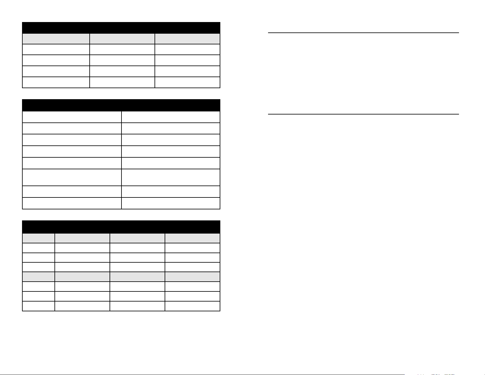
Mechanical Dimensions
DIM ½" Male ¾" Male 1" Male
A 2-7/16" (62mm) 2-7/16" (62mm) 2-7/16" (62mm)
B 7-11/16" (195mm) 8-1/32" (204mm) 8-3/32" (206mm)
Port Size NPTF ½", SAE #8 NPTF ¾", SAE #12 NPTF 1", SAE #16
DIM ½" Female ¾" Female 1" Female
A 2-7/16" (62mm) 2-7/16" (62mm) 2-7/16" (62mm)
B 7-5/32" (182mm) 7-9/16" (192mm) 7-9/16" (192mm)
Port Size NPTF ½", SAE #8 NPTF ¾", SAE #12 NPTF 1", SAE #16
Performance
Measuring accuracy: ±5% of full-scale
Repeatability: ±1% of full-scale
Flow Measuring Range: 1-30 GPM (5-110 LPM)
Turn Down Ratio (All Ranges:) 10:1
Maximum operating pressure: 325 PSIG (22.4 bar)
Maximum operating temperature:
FLC-W Series: 200°F (93°C)
FLC-H Series: 250°F (121°C)
Pressure Differential: See graph on right.
Filtration requirements: 74 Micron (200 U.S. mesh) min.
Materials of Construction (Wetted Components)
FLC-W Series FLC-H Series
End Ports Polysulphone Polysulphone
Seals Buna-N Buna-N
Spring Stainless Steel Stainless Steel
Indicator and Casing Polycarbonate Polysulphone
Page 4
Stabilized Contamination
The goal of filtration is to create effective protection from system
contamination. Proper filtration stabilizes contamination to allow fluid
components to function properly. A fluid system is considered
stabilized when, “contamination in” equals “contamination out”. Proper
filtration must reduce initial contamination to a stabilized level within
an acceptable time period. the system should be stabilized in time to
prevent premature wear or damage to meter components.
Contamination Sources
Fresh Fluid
When fresh fluid is stored in holding tanks, it may be contaminated
with scale or metal flakes from inside the tank. To prevent this type of
contamination, be sure to filter fresh fluid before adding to the system.
New Machinery Contamination
When building new machines, a certain amount of built-in
contamination is unavoidable. Typical built-in contamination consists
of dust, dirt, chips, fiber, and sand, flushing solutions, moisture, weld
splatters and pipe sealants. Flushing the system before operation can
reduce contamination, but cannot eliminate it totally.
Unless the system is flushed at a high velocity, some contamination
will not be dislodged until the system is in operation. System
contamination can cause fluid component malfunction.
Environmental Contamination
When performing routine maintenance, the system's fluid is
commonly exposed to environmental contamination. Exercise caution
during routine maintenance to prevent this type of contamination. Be
sure to change breather filter and systems air filter regularly.
Self-Generation Contamination
Self-generated contamination is a product of wear, cavitation, fluid
breakdown and corrosion. Systems that are carefully flushed,
maintained, and have fresh fluid added, mainly have self-generated
contamination. In this case, proper filtration can prevent fluid
component malfunction.
Page 9
Page 5

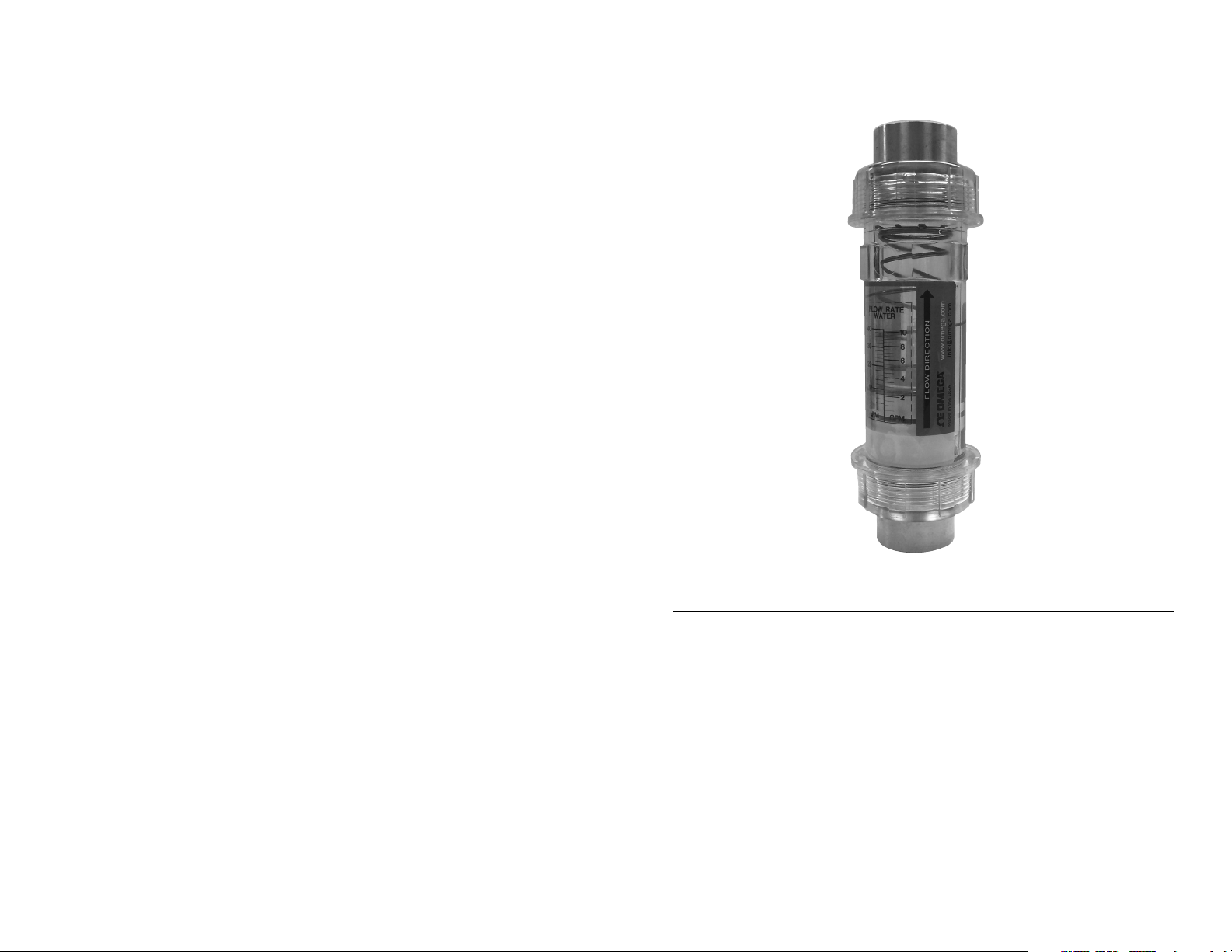
Basic Application Information
The flow meter can be installed directly in the fluid line without flow
straighteners or special piping. The meter is used to measure the flow
rate of most liquids which do not contain particles greater than 74 micron.
1) The casing and union retainers are made of either Polycarbonate
or Polysulphone materials permitting use with a variety of media.
Use of mild detergent to clean the meter body is encouraged to
prevent damaging the label or associated components.
2) The meter may be mounted in the most convenient location, in any
orientation to allow easy access for reading and maintenance.
3) The Meters should NOT be mounted near hot pipes or
equipment which can cause damage to the pressure vessel.
4) The Meters should not be mounted in a manner such
that piping misalignment or other system components can exert
force or produce a bending moment on the pressure vessel.
5) To retain accuracy and repeatability, internal moving parts are
closely toleranced and require filtration of at least 74 micron or a
200 mesh screen.
Basic Installation Information
The meters are mounted in-line and are direct reading. The meters
can be mounted in a vertical or horizontal position as long as the fluid
is flowing in the direction of the arrow on the flow scale. No straight
pipe is required before or after the meter. In fact, 90° elbows can be
installed on both ends without any noticeable flow variation. When
installing a meter, apply “Teflon Tape” on pipe threads. DO NOT apply
pipe dope or Teflon paste. If tape is used, be sure to leave 1/8" (3 mm)
of pipe thread exposed on end of pipe. Position filter in front of meter
and in a location that allows easy access for routine maintenance.
Refer to “Warnings and Precautionary Areas” for additional information.
INSTALLATION DOS AND DON'TS
To obtain satisfactory operation from the flow meter, the following
points should be considered:
Page 5
Reading the Meter
Notice the black reference line which runs 360° around the metering
poppet. This reference line moves under the scale in direct relation to
the movement of the poppet. When fluid is flowing, the flow rate
through the meter is read by lining up the black reference line with
the closest rate line on the flow scale.
Specific Gravity or Density Effect
Standard meters are calibrated for either WATER with a specific gravity of 1.0 or OIL with a specific gravity of .873. The floating disk meter
is affected by fluid density as are most other similar type meters.
Omega’s meters have less of this effect because of the sharpness of the
floating orifice disks being used. The indicated flow reading will read
high for heavier fluids and low for lighter fluids. A corrective factor can be
applied to the standard scale or a special scale can be added at a slight
additional costs. When measuring fluids with other specific gravities, the
basic equations below can be used to develop corrected readings.
CONTAMINATION AND FILTRATION
Recommended Filtration
The manufacturer recommends system filtration of at least 74 micron filter or a 200 mesh screen. It has been found that if inadequate filtration
has caused meter failure, it will normally fail in the open position. Some
systems may require a magnetic filter. IMPORTANT: Meter damage
caused by excessive contamination is not covered under warranty.
Page 8
Page 6
DO:
install a pressure gauge near the inlet of the meter
place throttling valves at the outlet of the meter
use pipe sealer on the connections
install solenoid valves at meter outlet (as far downstream as
possible)
mount in any orientation: vertical, horizontal or upside down
DO NOT:
place restrictions between the meter's pressure gauge meter inlet
use in systems where reverse flow is possible
place meter in non-aligned piping
over-flow the meter by more than 150% of maximum reading
operate at pressures and temperatures greater than specified
Warning and Precautionary Areas
1) The meters are designed to operate in systems that flow in only
one direction: the direction of the arrow on the flow scale.
Attempting operation in the reverse direction may cause damage
to the meter or other system components.
2) The pressure vessel and its associated components are made of
Polycarbonate on the FLC-W meters. Polycarbonate can
be safely cleaned with soap and water. However, many other
cleaning agents can damage Polycarbonate, causing discoloration
or crazing.
3) When installing onto threaded pipe, caution should be taken not to
over tighten the pipe connections or introduce torque on the main
body of the meter. The meter main body may rupture if overtightened.
4) Meter should not be used in systems where the assembled piping
is not supported. Externally applied piping forces may cause the
meter to rupture or malfunction.
5) Operating Temperature: In standard meters, several components
have a maximum temperature rating (see specifications).
Page 6
6) Operating Pressure: All meters are tested at a burst pressure three
times that of operating pressure. Meters should not be used over
the operating pressure rating.
7) Teflon tape: Caution should be used when using Teflon tape on
pipe thread joints. Leave at least 1/8" (3mm) of pipe thread
exposed from end of pipe when applying tape.
OPERATION
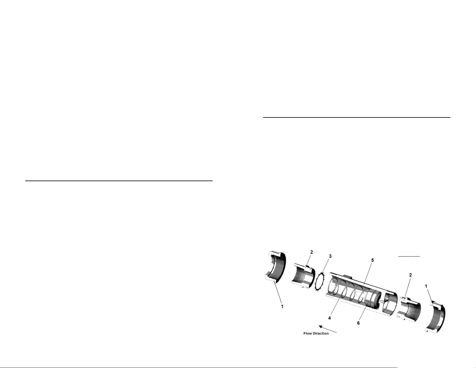
Operating Principles
Omega has developed a line of unique flow meters which combine
the simplicity of a sharp-edged orifice disk and a variable area flow
meter. See Figure 1 “Flow Meter Cross Section” below. The meters
are tubular, with all internal wetted parts sealed within the body
casing (5). Running through the center of the body casing is a
tapered center shaft which is centered in the bore. Encircling the shaft
is a sharp-edged, floating metering poppet (6). The metering poppet
is held in the “no flow” position by the biased return spring (4). As the
flow moves through the meter it creates a pressure differential across
the floating orifice disk, forcing the disk and transfer magnet against
the return spring. As flow increases, the pressure differential across
the metering poppet increases, forcing poppet to move along the
tapered center shaft. As flow decreases, the biased return spring
forces the poppet down the tapered center shaft, returning to the “no
flow” position.
Page 7
Figure 1:
Flow Meter Cross Section
 Loading...