

Page 1

FL9000-ACSERIES
Flowmeters
Operator’s Manual
Page 2
FLWOO-AC
SERIES INSTALLATION
OMEGA@
The
rugged proven technology of a direct reading,
type, variable area flowmeter, with a
solid state switching module This combination aids the
machine designer/troubleshooter by providing
taneous flow-rate
The
1.
plastic. Polysulfone is a strong
remains very stable to
precautions must be observed to ensure proper
performance.
a)
b)
cl
dJ
FL9000-AC
READ INSTRUCTIONS THOROUGHLY BEFORE INSTALLING FLOWMETER
FL9000-AC
The meter will melt, crack or distort if exposed to
an open flame or excessive heat. Therefore, DO
sweatfit
NOT
mounted to the plastic flowmeter body.
Pipe dope MUST NOT CONTACT the plastic
flowmeter body. Some pipe dope formulas will
react adversely with Polysulfone. If a sealing
material is necessary, use of Teflon tape is
recommended.
Do not over-tighten the threads on the plastic
flowmeter body. Overtightening NPT pipe
threads may cause fracturing of the plastic
flowmeter body.
Piping on the inlet and outlet of the flowmeter
must be aligned. Pay special attention to this
Flowmeter combines the
piston-
hermeticaiy
indrcation,
Flowmeter is made of polysulfone
brass fittings into a system while
coupled with the
?hermoplastic,
21O’F.
However, some
sealed,
instan-
IMPORTANT
and
s
electronic signal module, which automatically alerts the
operator. or controller if an incorrect flow rate is detected.
verification, pump testing, etc
2.
3.
4.
5.
.
Uses of this product include cooling
indication and verification, lubrication oil indication and
when high temperature, high pressure, or a
combination of both may be encountered.
e)
Check the compatibility of the fluid in the system
with the materials used in the flowmeter.
FL9000-AC
The
straight pipe at the inlet or outlet to stabilize the flow
through the meter.
FL9000-AC
The
orientation. Its design allows the designer/installer to
mount the flowmeter in horizontal piping, or vertical
piping, without affecting meter accuracy.
FL9000-AC
The
normally jam valves and other flow controls. If
particulate will be encountered, a 200 mesh or 74
micron filter is recommended.
Notice the “Flow Direction” arrow located on the
flowmeter scale The
valve to flow moving against the arrow.
DOES NOT require lengths of
can be mounted in any plane of
will tolerate particles that will
FL9000-AC
water/Glycol
will act as a check
Page 3
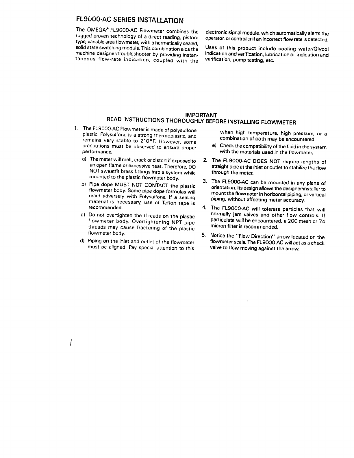
FLOW ALARM ASSEMBLY
RETAINING
(Fig. 1)
After the Flow Meter is installed, loosen the cap screw
on the electronic alar m assemb ly (see Figure 1). Adjust
the assembly so that the retaining band centers
approxi ma tely at the desired flow alar m position. Then,
retighten
cap screw securely. The module turns “on” as
BAND
flo w exceeds preset. The
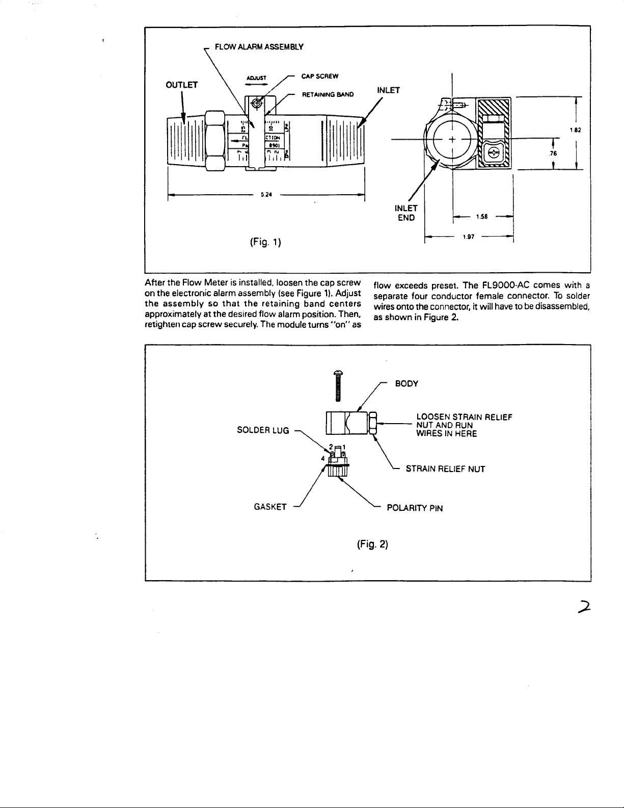
separate four conductor female connector. To solder
wires onto the connector, it will have to be disassembled,
as shown in Figure 2.
J
FL9000-AC comes w ith a
SOLDER LUG
GASKET
(Fig. 2)
LOOSEN STRAIN RELIEF
NUT AND RUN
W IRES IN HERE
STRAIN RELIEF NUT
2
Page 4

The connector has four
On the FL9000
3 and 4 are not used. On the
unit with the VAC flow alarm, terminals
flow alarm, terminal
solder lugs labeled
FL9DCKl
3 is not used. It should be noted
1.2.3
and 4.
unit with the VDC
before reassembly, which wire is connected to which
-
solder lug.
see
Color coding, or labeling the
6gures
3a
and
3b
wires is advised.
STRAIN RELIEF NUT
POlARlPl
(Fig.
After securing wires to solder lugs, a determination of the
orientation that the body of the connector should face.
needs to be
into the connector body, see Figure 4 below,
mada
PIN
3al
Before snapping the conductors back
4
After choosing orientation A, B or C, snap connector
back together, pull excess wires out of strain relief, and
tighten strain nut. Plug into electric housing and secure
with screw.
r
INLET OF FLOWMETER
-
ELECTRONIC
STRAIN RELIEF NUT
POLARITY PIN
(Fig.
HOUSING
3b)
3
POLARITY PIN
(Fig. 4)
Page 5

FL9000-AC
The
variety of different
is designed to turn “on” or “off” a
115VAC
loads. Examples of loads
include: Solenoid valves, warning lights and AC relay
coils. The module can only switch loads that consume
between 2.5 and 90 watts, or have 5000R to 150R
impedance respectively. If the load draws less than 2.5
watts, a loading capacitor is required. The capacitor ’s
value and connection is demonstrated in Figure 5. If the
load draws greater than 90 watts, a power relay is
necessary. Figs. 6 and 7 show typical relay connections.
Wiring Configurations:
Conventional Connection: See Fig. 5
1.
3 Load limited by relay contacts
3.
The Schematic in Fig. 5 will provide conduction over
15-20% of full scale above, or below the flow rate set
point.
LOADS CAP. MUST BE
RATED
XS’OOV
INWCT lVE
WITH
Fig. 5
foad
1
must draw between 2.5 and 90 watts. For
loads smaller than 2.5 watts, see
#2.
For loads
greater than 90 watts, see Figs. 6 and 7.
2 Loads consuming less than 2.5 watts require a
0.47
PF
capacitor connected as shown. This
capacitor will increase the power consumption and
ensure complete conduction.
2. Conventional Relay Connections: See Fig. 6
Fig. 6 demonstrates a SPDT relay with a 115 VAC coil
integrated with a flow alarm module. This
combination allows switching of loads up to the
rating of the relay contacts.
VW
11s
RELAY
1
Y
3
:
RELAY CONTACT
RI
I
I
I
4
I
Fig. 6
latching Relay Systems: See Fig. 7
The Flow Alarm Module can be integrated with
latching type relays, or a simple latching system can
be connected as in Fig. 7.
DPDT
RELAY
W
BUT
f
-1
I,
0
TON
“LLA,
0
RELAY CONTACT
LUNIACI
Y,
IF--- -
The module will turn the relay “on” as flow either
exceeds, or falls below the flow rate set point. The
relay will remain activated until the reset button is
depressed.
Page 6

Wiring Configurations for VDC Flow Alarm:
1. For relay output:
al Relays with coil voltage
between 7 and 24 VDC.
b)
Relays with coil voltage
between 4 and 60 VDC.
TTL/CMOS interface:
2. For
FROM
CONNECTOR
3. Other loads (eg. lamp, buzzer,
.
etc)
The load must draw less than
0.5 amps at 7-24 VDC. If the
load uses in excess of 0.5
amps or 24 VDC, section 1
wiring must be used.
Note: See specifications to avoid damage to FET (transistor).
CAUTION: To protect the FET from damage due to inductive
collapse, use a “catch” diode, as demonstrated in section 1 of wiring
configurations, when switching inductive loads such as solenoids
and relay coils. Connection of Terminal 1 directly to a voltage source
will destroy the unit.
VCLTAGE
Page 7

SPECIFICATIONS
ACCURACY:
REPEATABILITY:
MAX. TEMP./PRESSURE:
MAXIMUM PARTICLE SIZE:
SIZE:
CONNECTION:
MATERIAL:
f
7% full scale
f
1% full scale
7ooF;@
220 PSI
60
PSI at
74 microns for standard
units; 400 microns for
ribbed piston water
meters
3h”
1
FL-9200- ‘/(a”
FL-9000 and
Length
(‘A”
(1’/6”
Copper Tubing. FL-9000
and
Male
Polysulfone
210°F
across flats,
Length;
9100-5%
%”
O.D.) or 1” Nominal
O.D.)
Type M
FL9100-1”
NPT,
*
NominalFL9200-Fits
WETTED PARTS:
ALARM
SETPOINT:
RELAY:
Polysulfone,
steel,
barium ferrite
Proximity switch
triggering a
1 amp
over 25% of span, and
drops out above and
below that. Includes
mating connector. Relay
not field installable
Adjustable
stainless
Buna-N,
and
110
Relay pulls in
triac.
O-100%
VAC
FS
@
Page 8

ONLY
OUALlFlEO PERSONNEL. NO WARRANTY EXTENDED HEREIN WILL APPLY IF SUCH UNIT IS INSTALLED OR
U
SED BY
UNOUALIFIED PERSO
ARE NO OTHER WARRANTIES, EXPRESSED OR IMPLIED. INCLUDING BUT NOT LIMITED TO THE IMPLIED
WARRANTIES OF MERCHANTABILITY AN0 OF FITNESS FOR A PARTICULAR PURPOSE. OMEGA
ENGINEERING, INC IS NOT RESPONSIBLE FOR ANV DAMAGES OR LOSSES CAUSED TO OTHER
EOUIPMENT. WHETHER DIRECT. INDIRECT. INCIDENTAL. SPECIAL OR
PURCHASER MAY EXPERIENCE AS A RESULT OF THE INSTALLATION OR USE OF THE PRODUCT THE
BUYER ’S SOLE REMEDY FOR ANY BREACH OF THIS AGREEMENT BY OMEGA ENGINEERING. INC OR ANY
OF
ANY
BRV\CH
PAID BY THE
DIRECTLY AFFECTED BY SUCH BREACH.
EVERY PRECAUTION FOR ACCURACY HAS BEEN TAKEN IN THE PREPARATION OF THIS MANUAL.
HOWEVER, OMEGA ENGINEERING. INC. NEITHER ASSUMES
ERRORSTHAT
OF THE PRODUCTS IN ACCORDANCE WITH THE INFORMATION CONTAINED IN THE MANUAL.
WARRANTY BY OMEGA ENGINEERING, INC. SHALL NOT EXCEEDTHE PURCHASE PRICE
PURCnASER TO OMEGA ENGINEERING. INC. FOR THE UNIT OR UNITS OR
MAY APPEAR NOR ASSUMES
NNEL
. THERE ARE NO WARRANTIES EXCEPT AS STATED HEREIN. THERE
CONSEOUENTIAL. WHICH THE
LIABILITV FOR ANY DAMAGES THAT RESULT FROM THE USE
RESPONSIBILITV FOR ANY OMISSIONS OR
BYTHESE UNITS ARE INHERENTLY DANGEROUS AND ARE INTENDED TO BE INSTALLED AND USED
EOUIPMENT
=OMEGA
,,.
One Omega
Slamford,
‘,.“I%
ENGINEERING,INC.
‘rrrbu).“lo
I
Owe.
Box 4047
Connecncu:
““rpy,
ffi907-0047
Call OMEGA Toll Free ’.
Sales:
Customer Service: l-600-622-2378
Engineering Assistance:
CT:
(203)
‘In
And
Direct
telephone number (203)
CONTACT THE OMEGA CUSTOMER SERVICE DEPARTMENT TO OBTAIN AN AUTHORIZED
RETURN (AR) NUMBER. The designated AR number should then be marked on the outside of
the return package.
359.1660
lnlernabonal
all warranty and
To
1. Returnee ’s name,
2. Model end
Repalr
3.
OMEGA ’s policy is
Thai
possible.
OMEGA” is a
0
Copyright 1990 OMEGA ENGINEERING, INC. All rights reserved including illustrations.
in this manual may be reproduced
without
way our
regls:ered
writlen
1400-TGOMEGA
I
1-600-6246342
140047244361
repalr
delaya,
Serlal
Inrtructlons.
IO
make running changes, not model changes,
cuslomers
l-600-622-BEST
I
l-600-USA-WHEN
CABLE: OMEGA
TELEX: 996404
Return
requeats/lnqulriea
359.1660. BEFORE RETURNING ANY INSTRUMENT, PLEASE
alao please be
proceaalng rvold
address, and phone number.
numbem.
get the latest
EASYLINK: 62966934
FAX: (203) 3547700
Requests/lnqulrter
to OMEGA Customer Service Department,
sun, to Include:
in technology and
trademark of OMEGA ENGINEERING,
permission
In
any manner,
lrom
OMEGA ENGINEERING,
eflher wholly or
whenever an improvement is
engmeenng.
INC.
In
pan for any purpose whatsoever
INC.
Nolhing
Printed in U.S.A
M1174/0590
 Loading...