

Page 1
OMEGA
Tedinologl.a
An
L
Cmm,.myl/
FL2900/6900/7900/8900
FL2700B/6700B/7700B/87OOB
Serie s
Serie s
Pneumatic In-Line Flowmeters
Operator’s Manual: Ml
NOT use Aromatic
Do
guard. Do
Do NOT install this unit within 2 ft. of electrical transformers, high strength electric motors or other electro-magnetic devises
that could adversely effect the magnetic coupling between the Flow Indicator and the Piston Magnet.
The OMEGA’“’ Pneumatic In-Line Flowmeters monitor air flow rates
to determine optimum performance, flow regulator settings, or
pneumatic system performance. The
8700B Series feature direct reading scales for air flow. The
6900, 7900, and 8900 multi-pressure scales (from 40 to 130
mean accurate flow measurements can be made without the need
for conversion calculations for pressure variations.
INSTALLATION: The flowmeter can be mounted vertically or
horizontally in the flow line. Notice the flow arrow which is located
on the meter scale, showing the direction which the flow must
travel. The multi-pressure meter acts as a check valve in reverse flow.
CAUTION: The flowmeter contains a residual amount of petroleum
base test fluid. This fluid may be incompatible or hazardous with
some compressed gases.
All air meters must have a pressure gauge installed at the inlet port.
The gauge should have
than the actual pressure you are expecting to run. For example, if you
are running your pressure at 100
with a
PSIG
range of at least 125 PSIG. Flow straighteners are not
required at the inlet or exhaust ports. In fact, 90 degree elbows can
be at either end of the meter or both if necessary.
OPERATION: Inside the meter is a sliding piston moving against a
spring when the flow varies. This piston movement opens and
closes an orifice, which is followed on the outside of the meter by
a moving indicator ring, magnetically coupled to the internal piston.
The meter has a graduated scale calibrated for air in SCFM (standard
cubic feet per minute). The multi-pressure meters are calibrated for
inlet pressure ranges commonly used from 40
at
F.
The single pressure meters come standard with a single
70”
pressure scale calibrated for inlet pressure of 100
specified by customer.
NOT
PSIG
175/1094
,
CAUTION
use Loctite thread locker or liquid teflon as thread sealant.
Hydocarbons, Halogenated Hydrocarbons, Ketones or Ester-based fluids on (or near) polycarbonate
FL27OOB,
range capacity at least 25% higher
PSIG
you should have a gauge dial
IMPORTANT..... READ BEFORE INSTALLING!
67OOB,
77008, and
PSIG
PSIG
FL2900,
PSIG)
to 130 PSIG,
or otherwise
TO READ SINGLE PRESSURE SCALE METERS:
The flowmeters are available pre-calibrated at 100 PSIG,
56% Relative Humidity. You will be able to determine your air flow
to within
the center line on the indicator ring under the clear lexan dust guard.
When flow is moving through the meter, the indicator ring will move
along under the guard. The flow rate is determined by matching the
position of the indicator ring center line and it ’s related position on
the scale. When inlet pressure changes, the scale must be corrected
to the new inlet pressure. Temperature affects the scale so little that
in most cases it can be ignored.
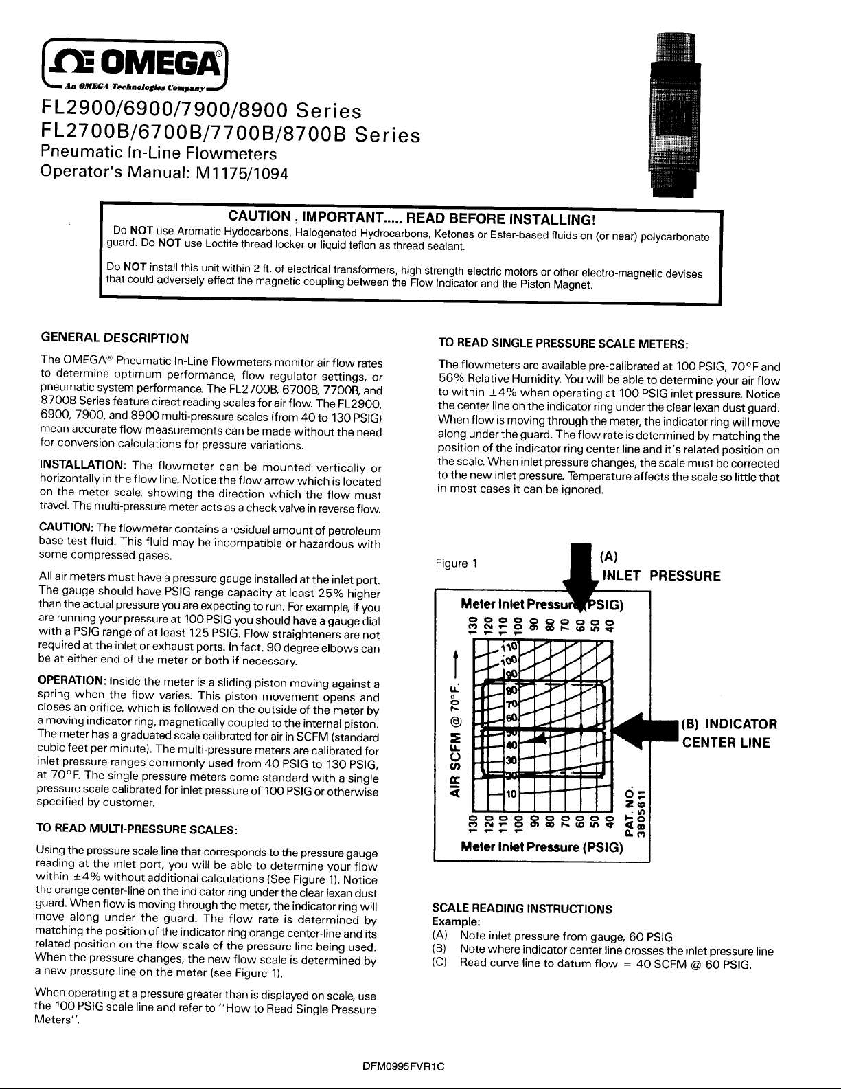
Figure
t4%
when operating at 100
1
PSIG
inlet pressure. Notice
70°F
and
INLET PRESSURE
Meter Inlet Press
(B) INDICATOR
CENTER LINE
TO READ MULTI-PRESSURE SCALES:
Using the pressure scale line that corresponds to the pressure gauge
reading at the inlet port, you will be able to determine your flow
within
t_4%
the orange center-line on the indicator ring under the clear lexan dust
guard. When flow is moving through the meter, the indicator ring will
move along under the guard. The flow rate is determined by
matching the position of the indicator ring orange center-line and its
related position on the flow scale of the pressure line being used.
When the pressure changes, the new flow scale is determined by
a new pressure line on the meter (see Figure 1).
When operating at a pressure greater than is displayed on scale, use
the 100
Meters”.
without additional calculations (See Figure
scale line and refer to “How to Read Single Pressure
PSIG
I).
Notice
SCALE READING INSTRUCTIONS
Example:
(A)
(B)
(C)
DFMO995FVRl C
Meter Inlet Pressure (PSIG)
Note inlet pressure from gauge, 60
Note where indicator center line crosses the inlet pressure line
Read curve line to datum flow = 40 SCFM
I
PSIG
@
60 PSIG.
Page 2
Use the three following basic steps for simple reading accuracy or
conversion.
Add the proper size pressure gauge to the line directly in front of
the Flowmeter inlet. If an air tool is used downstream of the
meter, you will notice no flow through the meter when the trigger
valve of the tool is in the on (closed) position, and the pressure
gauge will show system pressure.
Now, shift the valve or trigger and allow the air to flow through
the meter. Notice the pressure reading on the gauge If it is around
100 PSIG, at the pressure the flowmeter is calibrated, the air flow
can be read directly off the meter. If the pressure is higher or lower
than 100 PSIG, you must convert the scale (see Figure 2).
Conversion Example: Inlet gauge pressure = 50
PSIG
SCFM indicated on scale = 60 SCFM
(at 100
PSIG
pre-calibrated pressure)
Basic formula, SCFM (actual) = SCFM (indicated)
f l
ft
Basic equation =
= 114.7
?i
14.7 +
PSIG
Substituting your inlet pressure into the basic equation, in place of
PSIG:
.114.7
f,
=
(PSIG)
14.7 + 50
-J
NOW SCFM (actual) = 60 SCFM
= 1.33
@
100
PSIG
(indicated)
fl
PSIG
@
= 45 SCFM
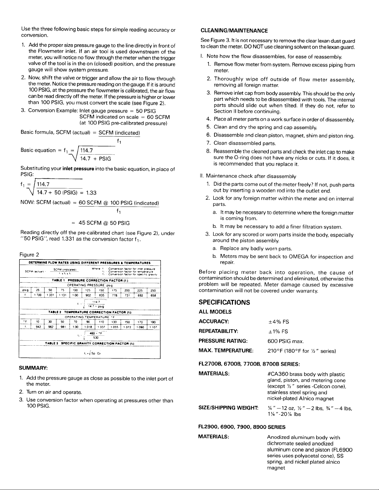
Reading directly off the pre-calibrated chart (see Figure
“50 PSIG ”, read 1.331 as the conversion factor
50
2), under
fl.
Figure 2
CLEANING/MAINTENANCE
See Figure 3. It is not necessary to remove the clear lexan dust guard
to clean the meter. DO NOT use cleaning solvent on the lexan guard.
I.
Note how the flow disassembles, for ease of reassembly.
1.
Remove flow meter from system. Remove excess piping from
meter.
2. Thoroughly wipe off outside of flow meter assembly,
removing all foreign matter.
3.
Remove inlet cap from body assembly. This should be the only
part which needs to be disassembled with tools. The internal
parts should slide out when tilted. If they do not, refer to
Section II before continuing.
4. Place all meter parts on a work surface in order of disassembly.
5. Clean and dry the spring and cap assembly.
6. Disassemble and clean piston, magnet, shim and piston ring.
7. Clean disassembled parts.
8.
Reassemble the cleaned parts and check the inlet cap to make
sure the O-ring does not have any nicks or cuts. If it does, it
is recommended that you replace it.
II.
Maintenance check after disassembly
1.
Did the parts come out of the meter freely? If not, push parts
out by inserting a wooden rod into the outlet end.
2.
Look for any foreign matter within the meter and on internal
parts.
a.
It may be necessary to determine where the foreign matter
is coming from.
b.
It may be necessary to add a finer filtration system.
3. Look for any scored or worn parts inside the body, especially
around the piston assembly.
a. Replace any badly worn parts.
b. Meters may be sent back to OMEGA for inspection and
repair.
Before placing meter back into operation, the cause of
contamination should be determined and eliminated, otherwise this
problem will be repeated. Meter damage caused by excessive
contamination will not be covered under warranty.
SUMMARY:
1.
Add the pressure gauge as close as possible to the inlet port of
the meter.
2. Turn on air and operate.
3. Use conversion factor when operating at pressures other than
100 PSIG.
SPECIFICATIONS
ALL MODELS
*4%
ACCURACY:
REPEATABILITY:
PRESSURE RATING:
MAX. TEMPERATURE:
7700B.
FL2700B.
6700B.
8700B SERIES:
MATERIALS:
SIZE/SHIPPING WEIGHT:
FL2900,6900,7900,8900
MATERIALS: Anodized aluminum body with
FS
+I%
FS
PSIG
600
210°F
max.
(180°F
for
%”
series)
#CA360 brass body with plastic
gland, piston, and metering cone
(except
%
V
series
-Celcon
stainless steel spring and
nickel-plated Alnico magnet
1/4”-1202,
1%“-20%
%“-2lbs.
Ibs
?/4”-4lbs.
SERIES
dichromate
sealed anodized
aluminum cone and piston
series uses polyacetal cone), SS
spring, and nickel plated alnico
magnet
cone),
(FL6900
Page 3

Figure 3
l/2”
Style Meter
lnlel
FLOW
14”
314”
l/4”,
l-1
--_)
Cap Cone
Style Meter
(L
Cone Assembly
Cap
Style Meter
Piston
Piston
Magnet
Magnet Ring
Ring
SPdnO
Outlet
ato
Body Assembly
(L
Cone
Cap
Model No.
FL2904
FL2909
FL2918
FL2924
FL6920
FL6960
FL6911
FL6915
FL7918
FL7950
FL7990
FL791 5
FL7922
FL8925
FL8945
FL8960
FL8980
FL8910
Assembly
Pkton
Flow Range
(SCFM)
1- 4
2- 9
2-
18
4-2 4
2-2 0
lo-60
-
110
10
-
150
20
4-1 8
5-5 0
IO-9 0
15
-
150
20
-
220
20
-
250
25
-
450
50
-
600
50
-
800
50
-
1000
Magnet
Port Size
i
Ring
‘/2
3/i
‘/,
Aaaombly
Body
Spring
Dimensions
OD
”‘h
”
”
1
”
1.4” 4.8”
1.8”
2.3”
4.0” 12.2”
Length
6.6”
7.2”
i
Model No.
FL2704B
FL2709B
FL2718B
FL2724B
FL676OB
FL6711B
FL6715B
FL7750B
FL7722B
FL8745B
FL876OB
FL878OB
FL871OB
@
SCFM
PSIG, 70°F
1-4
2-9
2-18
4-24
IO-60
10-110
20-150
5-50
20-220
100 FNPT
Port Size O.D .
”
l/4
”
%
”
3/i
1.4”
1.8”
2.3”
Length
4.8”
6.6”
7.2”
Page 4

Servicing USA and Canada: Call OMEGA Toll Free
One
USA
Omega Drive, Box 4047 976 Bergar
Stamford, CT 06907-0047
Telephone: (203) 359-1660
FAX: (203) 359-7700
Sales Service: l-800-826-6342
Customer Service: l-800-622-2378
Engineering Service: l-800-872-9436
TELEX: 996404 EASYLINK: 62968934 CABLE: OMEGA
Canada
Lava1 (Quebec)
Telephone: (514)
FAX: (514) 856-6886
l-800-TC-OMEGASM
/
l-800-622-BESTSM
/
I-SOO-USA-WHENSM
/
H7L
5Al
856-6928
Servicing Europe: United Kingdom Sales and Distribution Center
25
Swannington Road, Broughton Astley, Leicestershire
OMEGA warrants this unit to be free of defects
for a period of 13
period to the normal
that OMEGA ’s customers receive maximum coverage on each product. If the unit should malfunction, it must
be returned to the factory for evaluation. OMEGA ’s Customer Service Department will issue an Authorized
Return (AR) number immediately upon phone or written request. Upon examination by OMEGA, if the unit is
found to be defective it will be repaired or replaced at no charge. However, this WARRANTY is VOID if the
unit shows evidence of having been tampered with or shows evidence of being damaged as a result of
excessive
other operating conditions outside of OMEGA ’s control. Components which wear or which are damaged by
misuse are not warranted. These include contact points, fuses, and
OMEGA is
only warrants that the parts manufactured by it will be as specified and free of defects.
OMEGA MAKES NO OTHER WARRANTIES OR REPRESENTATIONS OF ANY KIND WHATSOEVER,
EXPRESSED OR IMPLIED, EXCEPT THAT OF TITLE AND ALL IMPLIED WARRANTIES INCLUDING
ANY WARRANTY OF MERCHANTABILITY AND FITNESS FOR A PARTICULAR PURPOSE ARE
HEREBY DISCLAIMED.
LIMITATION OF LIABILITY: The remedies of purchaser set forth herein are exclusive and the total
liability of OMEGA with respect to this order. whether based on contract, warranty, negligence,
indemnification, strict liability or otherwise, shall not exceed the purchase price of the
component upon which liability is based. In no event shall OMEGA be liable for consequential,
incidental or special damages.
Every precaution for accuracy has been taken in the preparation of this manual; however, OMEGA
ENGINEERING, INC. neither assumes responsibility for any omissions or errors that may appear nor assumes
liability for any damages that result from the use of the products in accordance with th e
information contained in the manual.
SPECIAL CONDITION: Should this equipment be used in or with any nuclear installation or activity, purchaser
will indemnify OMEGA and hold OMEGA harmless from any liability or damage whatsoever arising out of
the use of the equipment in such a manner.
months
porrosion;
glad
from date of purchase. OMEGA Warranty adds an additional one
(1)
one
or current, heat, moisture or vibration; improper specification; misapplication; misuse or
to
offer suggestions
year product warranty
on the use of its various products. Nevertheless, OMEGA
LE9
England
6TU.
In
materials and workmanship and to give satisfactory service
to cover handling and shipping time. This ensures
triacs.
(1)
month grace
Direct all warranty and repair requests/inquiries to the OMEGA ENGINEERING Customer Service Department.
BEFORE RETURNING ANY PRODUCT(S) TO OMEGA, PURCHASER MUST OBTAIN AN AUTHORIZED
RETURN (AR) NUMBER FROM OMEGA’S CUSTOMER SERVICE DEPARTMENT (IN ORDER TO AVOID PRO-
CESSING DELAYS). The assigned AR number should then be marked on the outside of the return package
and on any correspondence.
FOR
FOR
MANn
following information available BEFORE contacting
OMEGA-
1. P.O. number under which the product was
PURCHASED,
2. Model and serial number of the product under
warranty, and
3. Repair instructions and/or specific problems
relative to the product.
OMEGA’s policy is to make running changes, not model changes, whenever an improvement is possible.
This affords our customers the latest in technology and engineering.
OMEGA is a registered trademark of OMEGA ENGINEERING, INC.
0
Copyright 1995 OMEGA ENGINEERING, INC. All rights reserved. This documentation may not be copied,
photocopied, reproduced, translated, or reduced to any electronic medium or machine-readable form, in
whole or in part, without prior written consent of OMEGA ENGINEERING, INC.
RETURNS, please have the
NON-WARRANTY
consult OMEGA for current
charges. Have the following information available
BEFORE
l.P.O. number to
2. Model and serial number of product, and
3. Repair instructions and/or specific problems
contactina
caiibration,
relative to the product.
REPAIRS OR
reoair/calibration
OMEGA:
cover
the COST of the repair/
CALIBRATION,
 Loading...