

Page 1
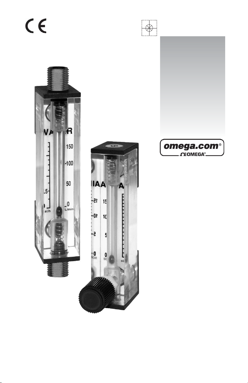
FL-2500
Acrylic Flow Meters
www.omega.com
e-mail: info@omega.com
User’s Guide
Shop online at
Page 2

Servicing North America:
USA: One Omega Drive, Box 4047
ISO 9001 Certified Stamford CT 06907-0047
Tel: (203) 359-1660 FAX: (203) 359-7700
e-mail: info@omega.com
Canada: 976 Bergar
Laval (Quebec) H7L 5A1
Tel: (514) 856-6928 FAX: (514) 856-6886
e-mail: info@ omega.ca
For immediate technical or application assistance:
USA and Canada: Sales Service: 1-800-826-6342 / 1-800-TC-OMEGA
®
Customer Service: 1-800-622-2378 / 1-800-622-BEST
®
Engineering Service: 1-800-872-9436 / 1-800-USA-WHEN
®
TELEX: 996404 EASYLINK: 62968934 CABLE: OMEGA
Mexico: En Espan˜ ol: (001) 203-359-7803 e-mail: espanol@ omega.com
FAX: (001) 203-359-7807 info@ omega.com.mx
Servicing Europe:
Benelux: Postbus 8034, 1180 LA Amstelveen, The Netherlands
Tel: +31 (0)20 3472121 FAX: +31 (0)20 6434643
Toll Free in Benelux: 0800 0993344
e-mail: sales@ omegaeng.nl
Czech Republic: Rude´ arm-dy 1868, 733 01 Karvin- 8
Tel: +420 (0)59 6311899 FAX: +420 (0)59 6311114
Toll Free: 0800-1-66342 e-mail: info@ omegashop.cz
France: 11, rue Jacques Cartier, 78280 Guyancourt, France
Tel: +33 (0)1 61 37 29 00 FAX: +33 (0)1 30 57 54 27
Toll Free in France: 0800 466 342
e-mail: sales@ omega.fr
Germany/Austria: Daimlerstrasse 26, D-75392 Deckenpfronn, Germany
Tel: +49 (0)7056 9398-0 FAX: +49 (0)7056 9398-29
Toll Free in Germany: 0800 639 7678
e-mail: info@ omega.de
United Kingdom: One Omega Drive, River Bend Technology Centre
ISO 9002 Certified Northbank, Irlam, Manchester
M44 5BD United Kingdom
Tel: +44 (0)161 777 6611
Toll Free in United Kingdom: 0800-488-48 FAX: +44 (0)161 777 6622
e-mail: sales@ omega.co.uk
OMEGAnet®Online Service Internet e-mail
www.omega.com info@ omega.com
It is the policy of OMEGA to comply with all worldwide safety and EMC/EMI regulations that
apply. OMEGA is constantly pursuing certification of its products to the European New Approach
Directives. OMEGA will add the CE mark to every appropriate device upon certification.
The information contained in this document is believed to be correct, but OMEGA Engineering, Inc. accepts
no liability for any errors it contains, and reserves the right to alter specifications without notice.
WARNING: These products are not designed for use in, and should not be used for, patient-connected applications.
Page 3

INSTALLATION AND OPERATING INSTRUCTIONS FOR
FL-2500 ACRYLIC FLOW METERS
UNPACKING THE FL-2500 ACRYLIC FLOW METER
Inspect Package for External Damage Your FL-2500 Acrylic Flow Meter was carefully
packed in a sturdy cardboard carton, with anti-static cushioning materials to withstand shipping shock. Upon receipt, inspect the package for possible external damage. In case of
external damage to the package contact the shipping company immediately.
Unpack the FL-2500 Acrylic Flow Meter Open the carton carefully from the top and inspect
for any sign of concealed shipping damage. In addition to contacting the shipping carrier
please forward a copy of any damage report to Omega
®
.
When unpacking the instrument please make sure that you have all the items indicated on
the Packing List. Please report any shortages promptly.
SPECIFICATIONS
Accuracy: ± 5% of full scale reading.
Float Materials: Glass (black colored), 316 Stainless Steel (silver colored), Tungsten
Carbide (Carboloy- silver colored).
Fittings: Brass or 316 Stainless Steel.
O-Rings: FKM is standard, Buna , EPR are optionally available.
Valves: Built-in needle valves are available.
Maximum Service Temperature: 65°C (150°F).
Maximum Service Pressure: 700 kPA (100 psig).
Scales: Direct reading dual scales mounted interchangeably at rear of flow meter block.
Each scale has both metric and English system units displayed. Scales are mounted by
means of locating holes between the rear of the acrylic block and the yellow colored backing plate. Customers can easily exchange scales for different fluids, and flow rates. Extra
scales and flow meter kits are available.
Float Readings: At center of ball shaped floats.
INSTALLATION
Mounting: Flow meters are shipped ready for panel (rear) mounting, and are easily con-
vertible to partial or full “in-line” configurations (see diagram). To convert, exchange Plug
Seals and Female Adaptors correspondingly using a 5/32" hex wrench and a 1/2 open box
wrench. Panel or “in-line” mounting is through 11/16" diameter holes, using hex nuts supplied.
1
Page 4

2
The following configurations are possible:
1) Panel Mounting, using hex nuts at rear of meter.
2) Full In-line Mounting (not available for meters with valve options.)
3) Partial In-line Mountings, i.e. inlet at bottom, outlet at top rear, or inlet at bottom
rear and outlet at top center.
TO EXCHANGE SCALES
No valve option
1) Using a 1/2" open box wrench or 5/16" hex wrench, remove rear fittings
(Female Adaptors for the panel mounting option or Plug Seals for the In-line
mounting option).
2) Remove Back Plate and Scale by sliding both to either side.
3) Holding the desired scale align its holes with those in the Back Plate. Slide
both behind the Bracket.
4) Insert but do not completely tighten fittings.
5) Recheck the Back Plate alignment.
6) Tighten fittings.
Valve option
1) Using a 1/2" open box wrench, remove top Female Adaptor.
2) Loosen the Valve Cartridge allowing the lower Female Adaptor to be
unscrewed. Do not remove Valve Cartridge from meter.
3) Remove Back Plate and Scale by sliding them to ether side.
4) Holding the desired scale align its holes with those in the Back Plate slide
them behind the Bracket.
5) Insert but do not completely tighten top Female Adaptor.
6) Insert but do not completely tighten lower Female Adaptor (it has an extra orifice
and an O-ring on it), while keeping the Valve Cartridge in place.
7) Screw Valve Cartridge into the lower Adaptor.
8) Recheck the Back Plate alignment.
9) Tighten Female Adaptors.
10) Tighten the Valve Cartridge. Do not over tighten it.
CLEANING
From time to time you may need to clean the meter. Disassembly has to be done in a clean
environment according to the following steps:
1) Unscrew the Plug Seal from the top of the unit with a 5/16" hex wrench.
2) Remove the Bumping Spring.
3) Flip the meter and let the spherical float fall out on to a clean surface. Float should
be handled with appropriate tweezers. Do not touch float with fingers. Store the
float in a clean box or bag free of grease.
Page 5

No valve option:
Unscrew the bottom Plug Seal and remove the Bumping Spring.
Valve option:
First unscrew the valve cartridge using a 1/2" open box wrench. Unscrew the
bottom Plug Seal and remove the Bumping Spring.
Clean with mild soup solution; dry out with air or inert gas.
Re-assembly starts with flipping the meter up side down.
1) Re-install the Bumping Spring in the bottom cavity;
For the valve option an extra step is required:
while squeezing the spring with appropriate flat stick, insert the valve cartridge
slowly, do not over tight it!
2) Insert the Plug Seal (both Seals are the same) carefully until it is flush with the
bracket.
3) Flip the meter over;
4) Insert the Float, the Bumping Spring and the Plug Seal until it is flush with
the bracket.
5) Shake the meter, making sure the ball is floating free, without restrictions.
3
Page 6
4
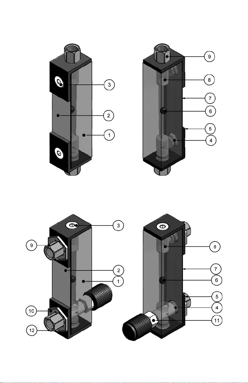
IN LINE VERSION
VALVE OPTION VERSION
Page 7

5
TYPICAL SCALES
PANEL MOUNT VERSION
PARTS LIST
ITEM QTY DESCRIPTION MATERIAL
1 1 Block Acrylic
2 1 Back Plate, yellow Polyethylene
3 2 Seal Plug
Brass or
316 stainless steel
4 4 O-ring FKM
5 2 Bracket Structural aluminum
6 1 Float
Glass or 316
stainless steel or
Carboloy
7 1 Scale Film
8 2 Bumping Spring 316 stainless steel
9 1 or 2 Female Adaptor
Brass or
316 stainless steel
10 2 Pal Nut Steel
11 1 Valve Cartridge
Wetted parts: PVDF
or Delrin, 316
stainless steel,
FKM O-ring
12 1
Female Adaptor for
Valve Cartridge
Brass or
316 stainless steel
Page 8

NOTES:
Page 9

NOTES:
9
Page 10

NOTES:
10
Page 11

WARRANTY/DISCLAIMER
OMEGA ENGINEERING, INC. warrants this unit to be free of defects in materials and workmanship for a
period of 13 months from date of purchase. OMEGA’s Warranty adds an additional one (1) month grace
period to the normal one (1) year product warranty to cover handling and shipping time. This ensures
that OMEGA’s customers receive maximum coverage on each product.
If the unit malfunctions, it must be returned to the factory for evaluation. OMEGA’s Customer Service
Department will issue an Authorized Return (AR) number immediately upon phone or written request.
Upon examination by OMEGA, if the unit is found to be defective, it will be repaired or replaced at no
charge. OMEGA’s WARRANTY does not apply to defects resulting from any action of the purchaser,
including but not limited to mishandling, improper interfacing, operation outside of design limits, improper repair, or unauthorized modification. This WARRANTY is VOID if the unit shows evidence of having
been tampered with or shows evidence of having been damaged as a result of excessive corrosion; or
current, heat, moisture or vibration; improper specification; misapplication; misuse or other operating conditions outside of OMEGA’s control. Components which wear are not warranted, including but not limited
to contact points, fuses, and triacs.
OMEGA is pleased to offer suggestions on the use of its various products. However, OMEGA neither assumes responsibility for any omissions or errors nor assumes liability for any damages
that result from the use of its products in accordance with information provided by OMEGA, either
verbal or written. OMEGA warrants only that the parts manufactured by it will be as specified and
free of defects. OMEGA MAKES NO OTHER WARRANTIES OR REPRESENTATIONS OF ANY KIND
WHATSOEVER, EXPRESS OR IMPLIED, EXCEPT THAT OF TITLE, AND ALL IMPLIED WARRANTIES
INCLUDING ANY WARRANTY OF MERCHANTABILITY AND FITNESS FOR A PARTICULAR PURPOSE ARE HEREBY DISCLAIMED. LIMITATION OF LIABILITY: The remedies of purchaser set forth
herein are exclusive, and the total liability of OMEGA with respect to this order, whether based on
contract, warranty, negligence, indemnification, strict liability or otherwise, shall not exceed the
purchase price of the component upon which liability is based. In no event shall OMEGA be liable
for consequential, incidental or special damages.
CONDITIONS: Equipment sold by OMEGA is not intended to be used, nor shall it be used: (1) as a
“Basic Component” under 10 CFR 21 (NRC), used in or with any nuclear installation or activity; or (2) in
medical applications or used on humans. Should any Product(s) be used in or with any nuclear
installation or activity, medical application, used on humans, or misused in any way, OMEGA assumes
no responsibility as set forth in our basic WARRANTY/ DISCLAIMER language, and, additionally,
purchaser will indemnify OMEGA and hold OMEGA harmless from any liability or damage whatsoever
arising out of the use of the Product(s) in such a manner.
RETURN REQUESTS/INQUIRIES
Direct all warranty and repair requests/inquiries to the OMEGA Customer Service Department.
BEFORE RETURNING ANY PRODUCT(S) TO OMEGA, PURCHASER MUST OBTAIN AN
AUTHORIZED RETURN (AR) NUMBER FROM OMEGA’S CUSTOMER SERVICE DEPARTMENT (IN
ORDER TO AVOID PROCESSING DELAYS). The assigned AR number should then be marked on the
outside of the return package and on any correspondence.
The purchaser is responsible for shipping charges, freight, insurance and proper packaging to prevent
breakage in transit.
FOR WARRANTY
RETURNS, please have the
following information available BEFORE
contacting OMEGA:
1. Purchase Order number under which
the product was PURCHASED,
2. Model and serial number of the product
under warranty, and
3. Repair instructions and/or specific
problems relative to the product.
FOR NON-WARRANTY REPAIRS,
consult OMEGA
for current repair charges. Have the following
information available BEFORE contacting OMEGA:
1. Purchase Order number to cover the
COST of the repair,
2. Model and serial number of the
product, and
3. Repair instructions and/or specific problems
relative to the product.
OMEGA’s policy is to make running changes, not model changes, whenever an improvement is possible.
This affords our customers the latest in technology and engineering.
OMEGA is a registered trademark of OMEGA ENGINEERING, INC.
© Copyright 2001 OMEGA ENGINEERING, INC. All rights reserved. This document may not be copied, photo-
copied, reproduced, translated, or reduced to any electronic medium or machine-readable form, in whole or in part,
without the prior written consent of OMEGA ENGINEERING, INC.
Page 12

Where Do I Find Everything I Need for
Process Measurement and Control?
OMEGA… Of Course!
Shop online at www.omega.com
TEMPERATURE
Thermocouple, RTD & Thermistor Probes, Connectors, Panels & Assemblies
Wire: Thermocouple, RTD & Thermistor
Calibrators & Ice Point References
Recorders, Controllers & Process Monitors
Infrared Pyrometers
PRESSURE, STRAIN AND FORCE
Transducers & Strain Gages
Load Cells & Pressure Gages
Displacement Transducers
Instrumentation & Accessories
FLOW/LEVEL
Rotameters, Gas Mass Flow meter & Flow Computers
Air Velocity Indicators
Turbine/Paddlewheel Systems
Totalizers & Batch Controllers
pH/CONDUCTIVITY
pH Electrodes, Testers & Accessories
Benchtop/Laboratory Meters
Controllers, Calibrators, Simulators & Pumps
Industrial pH & Conductivity Equipment
DATA ACQUISITION
Data Acquisition & Engineering Software
Communications-Based Acquisition Systems
Plug-in Cards for Apple, IBM & Compatibles
Datalogging Systems
Recorders, Printers & Plotters
HEATERS
Heating Cable
Cartridge & Strip Heaters
Immersion & Band Heaters
Flexible Heaters
Laboratory Heaters
ENVIRONMENTAL
MONITORING AND CONTROL
Metering & Control Instrumentation
Refractometers
Pumps & Tubing
Air, Soil & Water Monitors
Industrial Water & Wastewater Treatment
pH, Conductivity & Dissolved Oxygen Instruments
M-4697/0110
 Loading...