

Page 1

FL-2000-AL
Flowmeter Alarm
Page 2

Page 3
SPECIFICATIONS
Body Material: ABS
Spacer Material: SBR Rubber
Operating Temperature:
0-70°C; 32-160°F
Supply Voltage: 5VDC Regulated
Supply Current: 250mA
Output Signal: (Requires Advanced Power Supply) 0-5 Volt logic signal
Buzzer Volume: 90dB
Connector: RJ11
Environmental: Splash Resistant
DESCRIPTION
The FL-2000-AL Alarm is a non-contact sensor designed to alert when flow rates exceed defined
thresholds. The FL-2000-AL Alarm provides red and green LED’s visual status indicators, and a buzzer as an
audible indicator of flow rate status.
FEATURES
• Detects flow rates that exceed user settings.
• Integral red and green LED’s and audible buzzer indicate operating state.
• Low-level digital output (on / off) represents operating state (See Output Connector Section for details).
• Latching and Self-resetting modes.
• Latching mode will alarm continuously after a flow rate error, until the user resets the unit.
• Self-reset mode will stop alarming when flow returns to desired range, but will light both red and
green LED’s to indicate that an error had occurred.
• No calibration necessary.
• Rugged, splash resistant enclosure.
• Low power 5V input.
• Power options include basic supply or supply with battery back up and logic output.
• Multiple units may be installed on a single flow meter to provide multiple thresholds.
• Non-contact sensing system will not be damaged by contaminants in flow stream.
• Field installable while the flow meter is in use.
Page 4

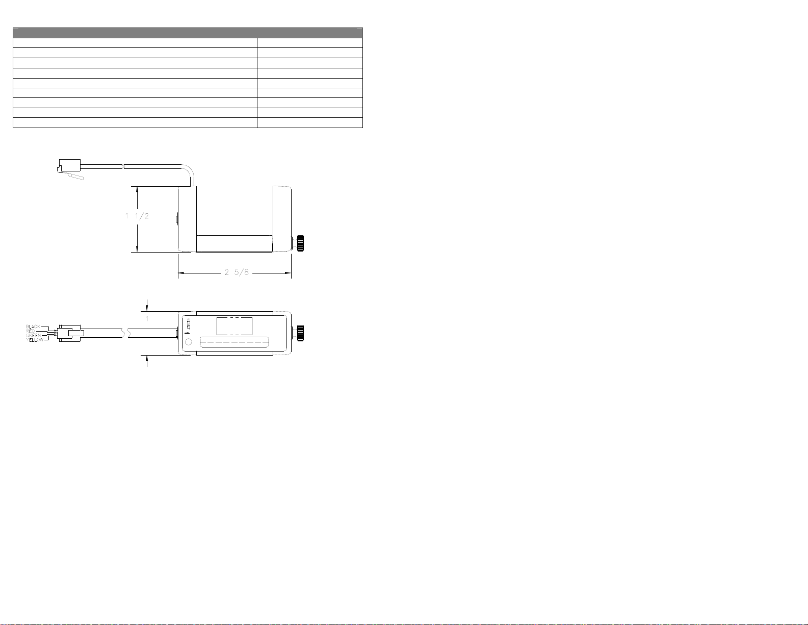
INSTALLATION
onto the front of the flow meter and tightening the thumbscrew. Included snap fit spacers (See Diagram 1) allow
the unit to fit various FL-2000 series flowmeters. See Table 1 to determine the proper pair of spacers to use for a
given flowmeter. The spacers are packed as a pair and are labeled on the end near the sensing holes. The FL2000-AL Alarm may be installed in an upward or downward orientation. The sensing line is offset to one end to
allow two FL-2000-AL Alarms to be installed over a narrow range on the flowmeter.
The FL-2000-AL Alarm is attached to a FL-2000 series acrylic flowmeter by placing the unit flush
DIAGRAM 1, SPACER INSTALLATION
FL-2000 SERIES GUIDE ROD SPACER NUMBER
FL-2071 to FL-2128 Y NO SPACER REQUIRED
FL-2001 to FL-2025 Y ESP003
FL-2001 to FL-2025 N ESP004
FL-2031 to FL-2057 Y ESP005
FL-2031 to FL-2057 N ESP006
FL-2060 to FL-2069 Y ESP007
TABLE 1, SPACER SELECTION
The FL-2000-AL Alarm uses an optical based sensing system, it is important that the flowmeter that it
is to be installed on is free of dirt, grease, and that no large scratches are present on the sides of the flowmeter. If
the flowmeter appears dirty or scratched, prepare the flowmeter for installation of the FL-2000-AL Alarm by
follow the cleaning instructions included with the flowmeter.
To set the alarm position, adjust the flow rate through the flow meter until the float is at the position
that would indicate and alarm. Place the FL-2000-ALAlarm on the flowmeter above or below the float, and slide
it towards the float until it alarms. Tighten the setscrew, return the flow to it normal rate, and reset the FL-2000AL Alarm. (See diagram 2).
DIAGRAM 2, SETTING ALARM LOCATION
Page 5

OPERATION
The FL-2000-AL Alarm may be operated in standard or self-reset mode. The unit requires no set up,
and will begin to operate as soon as it is connected to its power supply, and will operate in standard mode. To
operate in self-reset mode, hold the reset button while applying power. When operating without an error, the FL2000-AL Alarm will have a green LED lit.
Standard mode: In this mode, the FL-2000-AL Alarm will alarm when the float crosses the sensing
line, and will alarm until the reset button is pressed. While alarming, the red LED will be lit, the buzzer will
sound, and the logic output will change state.
Self-Reset mode: In this mode, the FL-2000-AL Alarm will alarm when the float crosses the sensing
line, and will reset when the float returns to the valid operating range. During normal operation, the green LED
will blink to note that the FL-2000-AL Alarm is in self-reset mode. While alarming, the red LED will be lit, the
buzzer will sound, and the logic output will change state. Upon returning to the valid range, the green LED will
begin to blink, and the red LED will blink to denote violations have occurred since the reset button was pressed.
O
UTPUT CONNECTOR AND PIN-OUT DESCRIPTION
The FL-2000-AL Alarm is provided with a male six pin modular RJ11 connector. This connector
provides the power input to the FL-2000-AL Alarm, as well as the logic output. If using the basic power supply,
the logic output is not available. This signal is available from a connector on the advanced power supply, or by
accessing pin 3 on the connector. The pin configuration for the included cable assembly is as follows:
PIN NUMBER SIGNAL WIRE COLOR
1 5VDC Black
2 N/A Red
3 LOGIC OUT (0-5V, 10mA) Green
4 GROUND Yellow
TABLE 2, OUTPUT CONNECTOR DEFINITION
DIAGRAM 3. OUTPUT CONNECTOR
POWER SUPPLY OPTIONS
The FL-2000-AL Alarm may be powered via three different options. These include the basic supply;
the advanced supply with universal input and battery backup, or the unit may be powered by the user (See Table 2
for pin definitions).
OPTION INPUT PART #
Basic Supply 120V AC (US plug only) FL-2000-PW
Advanced Supply w/Backup 100-240V AC; 9V Battery
FL-2000-PWA
(International plugs)
User Supplied Regulated 5VDC; 250mA N/A
TABLE 3, POWER SUPPLY OPTIONS
The advanced supply accepts AC power via a universal input adapter, which comes with interchangeable US,
European, and Asian style plugs. In addition, a 9V battery is used as battery backup during a power failure. A
fully charged 9V battery provides over two (2) hours of backup with the FL-2000-AL Alarm in alarm condition.
Backup time is longer if the FL-2000-AL Alarm is operating in a clear state. The supply also has a connector for
access to the logic output signal. The signal high (5V) when clear, and low (0V) when alarming. The signal can
source up to 25mA.
Page 6

TROUBLESHOOTING
Unit fails to operate Ensure that the unit is powered correctly.
Unit does not fit properly on
flowmeter
Unit does not alarm on flow
violation
Unit alarms when placed on
unit, will not reset
Unit will not stay in SelfReset mode.
Unit alarms without a flow
violation
Spacers will not attach to unit. Loosen the thumbscrew to facilitate spacer installation.
Problem Solution
Power the unit through an UPS to provide reliable power.
Ensure that proper spacers are being used and are properly installed.
Ensure that the unit is tight by checking the thumbscrew.
Ensure that proper spacers are being used.
Avoid shining bright light on the unit or flowmeter, it may cause
false readings.
Ensure that the unit is powered correctly.
Ensure that proper spacers are being used.
Ensure that the flow tube is free of build up, clean if necessary.
Ensure that sides of flowmeter are free of dirt, grease, and major
scratches.
If used on a liquid meter, ensure that liquid is clear and free of
bubbles.
Ensure that the unit is powered correctly. Unit defaults to standard
mode at power-up.
Ensure that unit is tight by checking thumbscrew.
If used on a liquid meter, ensure that liquid is clear and free of
bubbles.
Page 7

Page 8

M-4287/0206
 Loading...