

Page 1

omega.com
®
®
FL-1900 Series
Rotameters
Operator’s Manual:
INSTRUCTION
SHEET
M0360/0201
®
6
4
6
0.5
SLMP AIR 70° 7 14.7 PSIA
SECTION 1 INTRODUCTION
1.1 GENERAL DESCRIPTION
OMEGA®Series FL-1900 Rotameters provide an
economical and efficient means of flow rate indication
when accuracy is not critical. Typical applications
include purging, seal oil systems, bearing lubrication,
and cooling water flow indication.
Engineering design makes them especially suitable
for use with corrosive liquids and gases, and
installation in corrosive atmospheres.
The Series FL-1900 Rotameters are furnished with a
control valve, but are available without the valve.
Indicator body and supported frame are constructed
from stainless steel. Sealing parts are manufactured
from vinylidene fluoride resin (Kynar). O-ring seals
are Viton-A. The meter is totally enclosed within a
cover of high impact polycarbonate (Lexan).
1.2 SPECIFICATION
The following specifications apply to all models.
CAUTION
Do not use this meter in excess of the specified values
PRESSURE RATINGS: 200 psig maximum
TEMPERATURE RATING: 250
°
F maximum
REPEATABILITY: ± 0.5 % of full scale
ACCURACY: Meter specified to have an accuracy
of ± 10 % of maximum scale from
100 % to 10% of scale reading.
Conforms to ISA R.P. 16.1,
Specification 10-S-10
DIMENSION: See Figure 1.1
METERING TUBE: Borosilicate glass
END FITTINGS: 316SS
WINDOW SHIELD: High Impact Plastic
FLOAT STOPS: Teflon
TUBE PACKING: Viton
O - RINGS: Viton
SCALE: 65mm direct reading for air or water
SECTION 2 INSTALLATION
2.1 RECEIPT OF EQUIPMENT
When the equipment is received, the outside packing
cases should be checked for any damage incurred
during shipment. If the packing case is damaged, the
local carrier should be notified at once regarding his
liability.
Remove the envelope containing the shipping list.
Carefully remove the equipment from the packing
case. Make sure spare or replacement parts are not
discarded with the packing material. Inspect for
damaged or missing parts.
2.2 RETURN SHIPMENT
Do not return any merchandise without an Authorized
Return (AR) number. Call OMEGACustomer Service
Department at (203) 359-1660.
CAUTION
It is recommended that this publication be read in its entirety before
performing any operation. Failure to understand and follow these
instructions could result in serious personal injury and/or damage
to the equipment
WARNING
Glass metering tubes are designed for operation up to the maximum operating pressures and temperatures as specified
herein. Due to the inherent brittle characteristic of glass and conditions beyond our control, tube breakage could result
below specified operating conditions. Possible glass tube breakage represents a potential hazard to operating personnel;
therefore, operator protection should be supplied where operating pressures may exceed 50 psig.. A safety shield constructed
of 1/2 inch acrylic plastic may be used or the glass tube meter maybe replaced with an all metal (armored) meter.
Figure 1.1 Dimension Diagram
Page 2
2.3 FILTER INSTALLATION
It is recommended that a filter with a rating of two (2) microns
be installed on the inlet side of the meter. This filter will reduce
the amount of foreign matter that could impair operation of
meter.
2.4 INSTALLATION OF METER
a. Check the control valve is fully closed.
b. Check the valve body is fully seated in meter
frame. Finger tighten if necessary.
c. Slowly tip meter back and forth and check that
float has freedom to move.
d. Remove dust covers from the inlet and outlet connections.
e. Install inlet and outlet line connections. Inlet
connection is at the zero end of the meter
.
2.5 CONTROL VALVE REPOSITIONING PROCEDURE
The user may desire to change the control valve from
the inlet side of the meter to the outlet side. If meter
is installed in the line, make sure that flow is stopped
to the meter. Failure to do this may result in a safety
hazard.
a. Disconnect inlet and outlet lines to meter.
b. Remove metering tube and seal spindle. Refer to
paragraph 4.3
c. Remove check ball from inside seal spindle.
Retain check ball for future use.
d. Install seal spindle in meter body. Refer to
paragraph 4.4
e. Turn meter 180
°
from original position so control
valve is now on outlet and seal spindle is on inlet.
f. Install metering tube. Refer to paragraph 4.4
g. Connect inlet and outlet lines to meter.
SECTION 3 OPERATION
3.1 GENERAL
After the meter has been installed it is ready for
operation. During operation make sure that meter
temperature and pressure specifications are not exceeded,
as stated in paragraph 1.2
When the valve stem knob is turned counterclockwise to
the stop, the valve is fully open. Flow indication is
measured using the center of the float as the reference
point. A check valve is incorporated within the seal
spindle. The check valve prevents reverse flow through
the meter when upstream flow is stopped. When the
control valve is installed on the outlet of the meter, the
check valve is not included.
SECTION 4 MAINTENANCE
4.1 GENERAL
No periodic maintenance, oiling, or cleaning is required
for the meter or meter components when it is used in
normal applications. It may be necessary to remove the
metering tube and components for cleaning when various
liquids have stained or left a deposit.
It is recommended that the meter and meter components
be ultrasonically cleaned if possible. If ultrasonic cleaning
is not available, use a suitable solvent. Tube and float may
be cleaned with a pipe cleaner or similar accessory.
4.2 SERVICE INFORMATION
Should this equipment require repair or adjustment,
contact OMEGA ENGINEERING Customer Service
Department at (203) 359-1660.
It is important that servicing be performed only by
trained and qualified service personnel. If this
equipment is not properly serviced, serious personal
injury and/or damage to the equipment could result.
4.3 DISASSEMBLY PROCEDURE (SEE FIGURE 5.1)
a. Remove shield (8) by squeezing sides at top and
bottom, and pulling forward.
b. Hold metering tube (1), and rotate seal spindle (4)
to the right until the stop is reached. Remove
metering tube.
c. Using tweezers, remove outlet float stop (2).
Remove float from metering tube. Be careful not
to drop float. Remove inlet float stop (2). If float is
stuck in metering tube, a rod (wooden dowel or
pipe cleaner preferred) may be inserted through
the inlet end of the tube, and the float pushed
through. Care must be taken not to score or
scratch the tube.
d. Depress seal spindle retainer tab. Rotate seal
spindle (4) to the left until it is disengaged from
the meter. Be careful not to drop the check ball (6)
from inside the seal spindle. Remove check ball.
e. Remove control valve (9) from meter body.
4.4 ASSEMBLY PROCEDURE (SEE FIGURE 5.1)
After the meter and the meter components have been
cleaned or checked, the following assembly procedures
should be followed. A separate assembly procedure
for the control valve is given in paragraph 4.6
a. Insert control valve body into meter frame and
finger tighten to secure.
b. Insert check ball (6) into seal spindle (4). Check for
freedom of movement.
c. Depress seal spindle retainer tab. Insert seal
spindle (4) into end fitting, and turn to the right
until fully seated. Release seal spindle retainer.
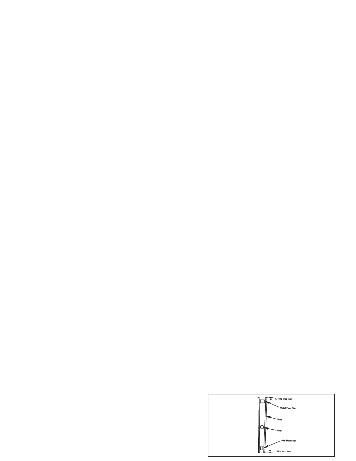
d. Insert inlet float stop (2) through outlet end of
metering tube. Using a rod (wooden dowel or
pipe cleaner preferred) push inlet float stop
through metering tube until it is approximately
1
/16 to 1/32 inch from end of metering tube.
(See Figure 4.2).
e. Insert float into metering tube.
f. Insert outlet float stop (2). Push float stop into
metering tube, until it is seated approximately
1
/16 to 1/32 inch from end of tubes. (See Figure 4.2).
Figure 4.2 Float Stop Installation Diagram
Page 3

g. Check the tubular inserts protrude from packings
approximately
1
/32 inch. if not, use tweezers and
reposition.
h. Insert metering tube into meter frame.
i. Center metering tube over the center of the
packings.
j. Rotate seal spindle to the left until a complete seal
between the metering tube and the packings is
accomplished.
k. After the flowmeter has been re-assembled, it is
important that it be hydrostatically tested at a liquid
pressure rating of 300 psig at room temperature.
4.5 CONTROL VALVE DISASSEMBLY PROCEDURE
When it is necessary to disassemble the control valve
for cleaning or to check components, the following
procedure should be followed. It is recommended that
the control valve be ultrasonically cleaned. If ultrasonic
cleaning is not available, use a suitable solvent.
a. Before removing control valve, stop all flow to meter.
b. Rotate valve stem knob to the left until valve is fully
open.
c. Rotate valve body to the left, and remove from meter
frame.
d. Make sure orifice and orifice o-ring are removed
from meter body.
e. Remove o-rings from valve.
f. Turn knob clockwise as far as possible.
g. Loosen set-screw in knob and remove knob.
h. Continue turning valve stem in a clockwise direction
to remove the stem from the bonnet.
i. Remove orifice from stem.
4.6 CONTROL VALVE ASSEMBLY PROCEDURE
After the control valve components have been cleaned
or checked, the following assembly procedures should
be followed:
a. It is recommended the valve stem threads be
lubricated with a molybdenum disulfide type
lubricant and all 0-rings be lubricated with a
silicone lubricant.
b. Insert the valve stem into the bonnet and turn the
stem counterclockwise (viewed from knob end) as
far as possible.
c. Install knob on stem and align set-screw with
detent in stem. Tighten set-screw.
d. Install the small orifice o-ring on orifice and insert
orifice in end of bonnet. Place the orifice on a flat
surface and gently apply downward pressure
until the orifice is properly seated in the bonnet.
e. Install large o-ring on the bonnet.
SECTION 5 PARTS LIST
5.1 RECOMMENDED SPARE AND REPLACEMENT PARTS
When ordering parts be sure to specify the following:
SERIAL NUMBER, complete equipment model number,
part description and part number. Refer to
Figure 5.1 for part reference.
CAUTION
Hydrostatic testing should be performed only by
trained and qualified personnel or serious
damage could result.
NOTE
Do not remove the two small 0-rings from valve stem.
Model No. Model No.Float Float
Range
SCFH AIR*
Range
GPH WATER*
Pressure
Drop
Inches Water **
Pressure
Drop
Inches Water **
FL-1901
FL-1902
FL-1903
FL-1904
FL-1905
FL-1906
FL-1907
FL-1908
FL-1909
FL-1910
FL-1911
FL-1912
FL-1951
FL-1952
FL-1953
FL-1954
FL-1955
FL-1956
FL-1957
FL-1958
FL-1959
FL-1960
FL-1961
FL-1962
Glass
Glass
316SS
Glass
316SS
Glass
316SS
Glass
316SS
Glass
316SS
Carboloy
Glass
316SS
316SS
Glass
316SS
Glass
316SS
Glass
316SS
Glass
316SS
Carboloy
0.2 - 1.2
0.2 -2.0
0.5 - 5.0
0.5 - 6.0
1.0 - 10
1.2 - 12
2.0 - 18
5.0 - 45
10.0 -80
5.0 - 55
10.0 - 90
12.0 -120
0.01 - 0.14
0.05 -0.5
0.1 - 1.0
0.05 - 0.7
0.10 - 1.6
0.2 - 2.0
0.5 - 4.0
1.0 - 9.0
2.0 -17
1.0 - 11
2.0 - 20
3.0 -30
1
2.2
10.8
12.4
10.1
10.4
25
60
214
73
292
400
1.8
4.0
19.5
22.3
18.3
18.7
45
109
385
132
525
890
*Air Flow Given At 14.7 psia and 70
0
F **Pressure Drops Are Approximate
Figure 5.1 Exploded View, FL-1900
Page 4

Servicing North America:
USA:
One Omega Drive, Box 4047
ISO 9001 Certified Stamford CT 06907-0047
Tel: (203) 359-1660 FAX: (203) 359-7700
e-mail: info@omega.com
Canada: 976 Bergar
Laval (Quebec) H7L 5A1
Tel: (514) 856-6928 FAX: (514) 856-6886
e-mail: info@omega.ca
For immediate technical or application assistance:
USA and Canada:
Sales Service: 1-800-826-6342 / 1-800-TC-OMEGA
®
Customer Service: 1-800-622-2378 / 1-800-622-BEST
®
Engineering Service: 1-800-872-9436 / 1-800-USA-WHEN
®
TELEX: 996404 EASYLINK: 62968934 CABLE: OMEGA
Mexico: En Espan˜ol: (001) 203-359-7803 e-mail: espanol@omega.com
FAX: (001) 203-359-7807 info@omega.com.mx
Servicing Europe:
Benelux:
Postbus 8034, 1180 LA Amstelveen, The Netherlands
Tel: +31 (0)20 3472121 FAX: +31 (0)20 6434643
Toll Free in Benelux: 0800 0993344
e-mail: nl@omega.com
Czech Republic: Rude´ arma´dy 1868, 733 01 Karvina´ 8
Tel: +420 (0)69 6311899 FAX: +420 (0)69 6311114
Toll Free: 0800-1-66342 e-mail: czech@omega.com
France: 9, rue Denis Papin, 78190 Trappes
Tel: +33 (0)130-621-400 FAX: +33 (0)130 699 120
Toll Free in France: 0800 4 06342
e-mail: france@omega.com
Germany/Austria: Daimlerstrasse 26, D-75392 Deckenpfronn, Germany
Tel: +49 (0)7056 9398-0 FAX: +49 (0)7056 9398-29
Toll Free in Germany: 0800 639 7678
e-mail: germany@omega.com
United Kingdom: One Omega Drive, River Bend Technology Centre
ISO 9002 Certified Northbank, Irlam, Manchester
M44 5EX United Kingdom
Tel: +44 (0)161 777 6611 FAX: +44 (0)161 777 6622
Toll Free in United Kingdom: 0800-488-488
e-mail: sales@omega.co.uk
OMEGAnet®On-Line Service Internet e-mail
www.omega.com info@omega.com
FOR WARRANTY RETURNS, please have the
following information available BEFORE contacting
OMEGA:
1. Purchase Order number under which the
product was PURCHASED,
2. Model and serial number of the product under
warranty, and
3. Repair instructions and/or specific problems
relative to the product.
FOR NON-WARRANTY REPAIRS,
consult OMEGA
for current repair charges. Have the following
information available BEFORE contacting OMEGA:
1. PurchaseOrder number to cover the COST
of the repair,
2. Model and serial number of the product, and
3. Repair instructions and/or specific problems
relative to the product.
OMEGA’s policy is to make running changes, not model changes, whenever an improvement is possible. This affords our customers the
latest in technology and engineering.
OMEGA is a registered trademark of OMEGA ENGINEERING, INC.
© Copyright 2001 OMEGA ENGINEERING, INC. All rights reserved. This document may not be copied, photocopied, reproduced, translated, or
reduced to any electronic medium or machine-readable form, in whole or in part, without the prior written consent of OMEGA ENGINEERING, INC.
WARRANTY / DISCLAIMER
OMEGA ENGINEERING, INC. warrants this unit to be free of defects in materials and workmanship for a period of
13 months from date of purchase. OMEGA’s Warranty adds an additional one (1) month grace period to the normal one (1) year product warranty to cover handling and shipping time. This ensures that OMEGA’s customers
receive maximum coverage on each product.
If the unit malfunctions, it must be returned to the factory for evaluation. OMEGA’s Customer Service Department will issue
an Authorized Return (AR) number immediately upon phone or written request. Upon examination by OMEGA, if the unit is
found to be defective, it will be repaired or replaced at no charge. OMEGA’s WARRANTY does not apply to defects resulting
from any action of the purchaser, including but not limited to mishandling, improper interfacing, operation outside of design
limits, improper repair, or unauthorized modification. This WARRANTY is VOID if the unit shows evidence of having been
tampered with or shows evidence of having been damaged as a result of excessive corrosion; or current, heat, moisture
or vibration; improper specification; misapplication; misuse or other operating conditions outside of OMEGA’s control.
Components which wear are not warranted, including but not limited to contact points, fuses, and triacs.
OMEGA is pleased to offer suggestions on the use of its various products. However, OMEGA neither
assumes responsibility for any omissions or errors nor assumes liability for any damages that result
from the use of its products in accordance with information provided by OMEGA, either verbal or
written. OMEGA warrants only that the parts manufactured by it will be as specified and free of
defects. OMEGA MAKES NO OTHER WARRANTIES OR REPRESENTATIONS OF ANY KIND
WHATSOEVER, EXPRESS OR IMPLIED, EXCEPT THAT OF TITLE, AND ALL IMPLIED WARRANTIES
INCLUDING ANY WARRANTY OF MERCHANTABILITY AND FITNESS FOR A PARTICULAR PURPOSE
ARE HEREBY DISCLAIMED. LIMITATION OF LIABILITY: The remedies of purchaser set forth herein are
exclusive, and the total liability of OMEGA with respect to this order, whether based on contract,
warranty, negligence, indemnification, strict liability or otherwise, shall not exceed the purchase
price of the component upon which liability is based. In no event shall OMEGA be liable for
consequential, incidental or special damages.
CONDITIONS: Equipment sold by OMEGA is not intended to be used, nor shall it be used: (1) as a “Basic
Component” under 10 CFR 21 (NRC), used in or with any nuclear installation or activity; or (2) in medical
applications or used on humans. Should any Product(s) be used in or with any nuclear installation or activity,
medical application, used on humans, or misused in any way, OMEGA assumes no responsibility as set forth in our
basic WARRANTY/ DISCLAIMER language, and, additionally, purchaser will indemnify OMEGA and hold OMEGA
harmless from any liability or damage whatsoever arising out of the use of the Product(s) in such a manner.
RETURN REQUESTS / INQUIRIES
Direct all warranty and repair requests/inquiries to the OMEGA Customer Service Department. BEFORE RETURNING
ANY PRODUCT(S) TO OMEGA, PURCHASER MUST OBTAIN AN AUTHORIZED RETURN (AR) NUMBER FROM
OMEGA’S CUSTOMER SERVICE DEPARTMENT (IN ORDER TO AVOID PROCESSING DELAYS). The assigned AR
number should then be marked on the outside of the return package and on any correspondence.
The purchaser is responsible for shipping charges, freight, insurance and proper packaging to prevent breakage in transit.
WARNING
FLOWMETER OPERATION
If the inlet and outlet valves adjacent to the flowmeter are to be closed for any reason, the flowmeter must be completely drained.
Failure to do so may result in thermal expansion of the liquid which can cause rupture of the meter and possible personal injury.
RECOMMENDED INSTALLATION PRACTICES
Water Hammer and surges can be damaging to any flowmeter and must always be avoided.
Water hammer occurs when a liquid flow is suddenly stopped as with quick closing and solenoid operated valves. Surges occur
when flow is suddenly begun, as when a pump is turned on at full power or a valve is quickly opened.
Liquid Surges are particularly damaging to flowmeters if the pipe is originally empty. To avoid damaging surges, fluid lines
should remain full (if possible) and pumps should be brought up to power slowly and valves opened slowly. In addition, to
both water hammer and surges, a surge chamber should be installed.
* Recommended Spare Parts
omega.comomega.com
®
®
 Loading...