

Page 1
www.omega.com
e-mail: info@omega.com
User’s Guide
FL1650 / 1660 SERIES
Industrial Rotameters
Shop online at
000
000000
000
000
000
000
000
000
000
000
000
000
000
000
000
00
00
00
00
00
00
00
00
00
00
0
MILLIMETER
WARNING TIGHTEN
ALL
SCREWS BEFORE
OPERATING METER
Page 2

Servicing North America:
USA: One Omega Drive, P.O. Box 4047
ISO 9001 Certified Stamford CT 06907-0047
TEL: (203) 359-1660 FAX: (203) 359-7700
e-mail: info@omega.com
Canada: 976 Bergar
Laval (Quebec) H7L 5A1
TEL: (514) 856-6928 FAX: (514) 856-6886
e-mail: info@omega.ca
For immediate technical or application assistance:
USA and Canada: Sales Service: 1-800-826-6342 / 1-800-TC-OMEGA
®
Customer Service: 1-800-622-2378 / 1-800-622-BEST
®
Engineering Service: 1-800-872-9436 / 1-800-USA-WHEN
®
TELEX: 996404 EASYLINK: 62968934 CABLE: OMEGA
Mexico: En Espan˜ ol: (001) 203-359-7803 e-mail: espanol@omega.com
FAX: (001) 203-359-7807 info@omega.com.mx
Servicing Europe:
Benelux: Postbus 8034, 1180 LAAmstelveen, The Netherlands
TEL: +31 (0)20 3472121 FAX: +31 (0)20 6434643
Toll Free in Benelux: 0800 0993344
e-mail: nl@omega.com
Czech Republic: Rudé armády 1868, 733 01 Karviná 8
TEL: +420 (0)69 6311899 FAX: +420 (0)69 6311114
Toll Free: 0800-1-66342 e-mail: czech@omega.com
France: 9, rue Denis Papin, 78190 Trappes
TEL: +33 (0)130 621 400 FAX: +33 (0)130 699 120
Toll Free in France: 0800-4-06342
e-mail: france@omega.com
Germany/Austria: Daimlerstrasse 26, D-75392 Deckenpfronn, Germany
TEL: +49 (0)7056 9398-0 FAX: +49 (0)7056 9398-29
Toll Free in Germany: 0800 639 7678
e-mail: germany@omega.com
United Kingdom: One Omega Drive, River Bend Technology Centre
ISO 9002 Certified Northbank, Irlam, Manchester
M44 5EX United Kingdom
TEL: +44 (0)161 777 6611 FAX: +44 (0)161 777 6622
Toll Free in United Kingdom: 0800-488-488
e-mail: sales@omega.co.uk
OMEGAnet®Online Service Internet e-mail
www.omega.com info@omega.com
It is the policy of OMEGA to comply with all worldwide safety and EMC/EMI regulations that
apply. OMEGA is constantly pursuing certification of its products to the European New Approach
Directives. OMEGA will add the CE mark to every appropriate device upon certification.
The information contained in this document is believed to be correct, but OMEGA Engineering, Inc. accepts
no liability for any errors it contains, and reserves the right to alter specifications without notice.
WARNING: These products are not designed for use in, and should not be used for, patient-connected applications.
Page 3

TABLE OF CONTENTS
FL-1650/1660
SECTION PAGE
SECTION 1 INTRODUCTION 1
1.1 General Description 1
1.2 Principle of Operation 4
1.3 factors that Affect Operation 4
SECTION 2 INSTALLATION 5
2.1 Unpacking 5
2.2 Installation Considerations 5
2.3 Panel Mounting 6
SECTION 3 OPERATION 8
3.1 Pre-Operational Check 8
3.2 Operating Procedure 8
SECTION 4 MAINTENANCE 9
SECTION 5 SPECIFICATIONS 10
i
Page 4
SECTION 1 INTRODUCTION
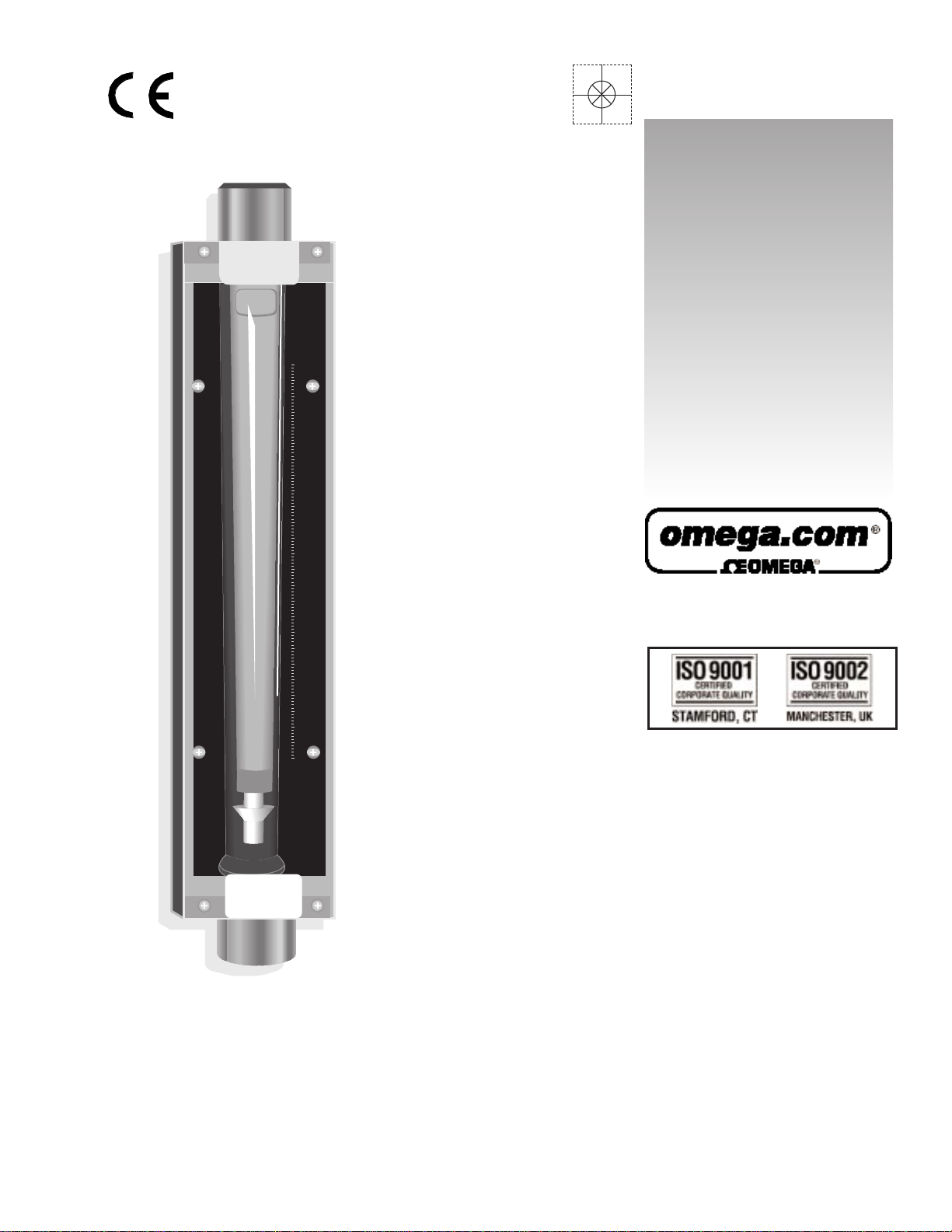
1.1 GENERAL DESCRIPTION
The OMEGA
®
FL1650/1660 Series Rotameters provide high accuracy in a rugged, industrial
housing. Standard construction has brass end fittings for mounting. The meters feature ±2%
full scale accuracy, ±1/2% full scale repeatability, and are shielded for use in pressurized
systems. The rotameters are supplied with arbitrary 10-100% scale, with multiplication
factors for air and water.
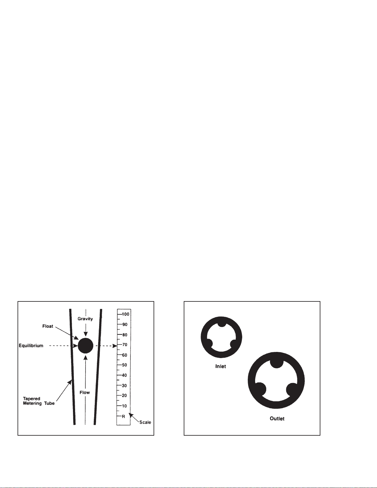
1.2 PRINCIPLE OF OPERATION
The operating parts of the flowmeter consist of a tapered glass tube and a float which operates
within the tube. The fluid enters the bottom of the tube, which has the smallest inside diameter
(and smallest area), and exits from the top, which has the largest inside diameter (and largest
area). Refer to Figure 1-1. The float is free to operate between the largest and smallest areas
of the tube.
As the float moves up and down within the tapered tube, the annular area between the float and
tube varies (area increases as the float rises). Refer to Figure 1-2. This gives the generic name
of “variable area meter” for this measurement principle. The pressure differential across the
float (bottom to top) is fixed by the weight of the float and the buoyant forces of the fluid. As the
flow varies, the float will move within the tube until it reaches an equilibrium position, where the
tube taper creates an appropriate annular area to balance the force of gravity and the fluid
forces acting on the float.
Figure 1-1 Principle of Operation Figure 1-2 Cross-section of FL 1650/60 Flow Tubes
1
Page 5
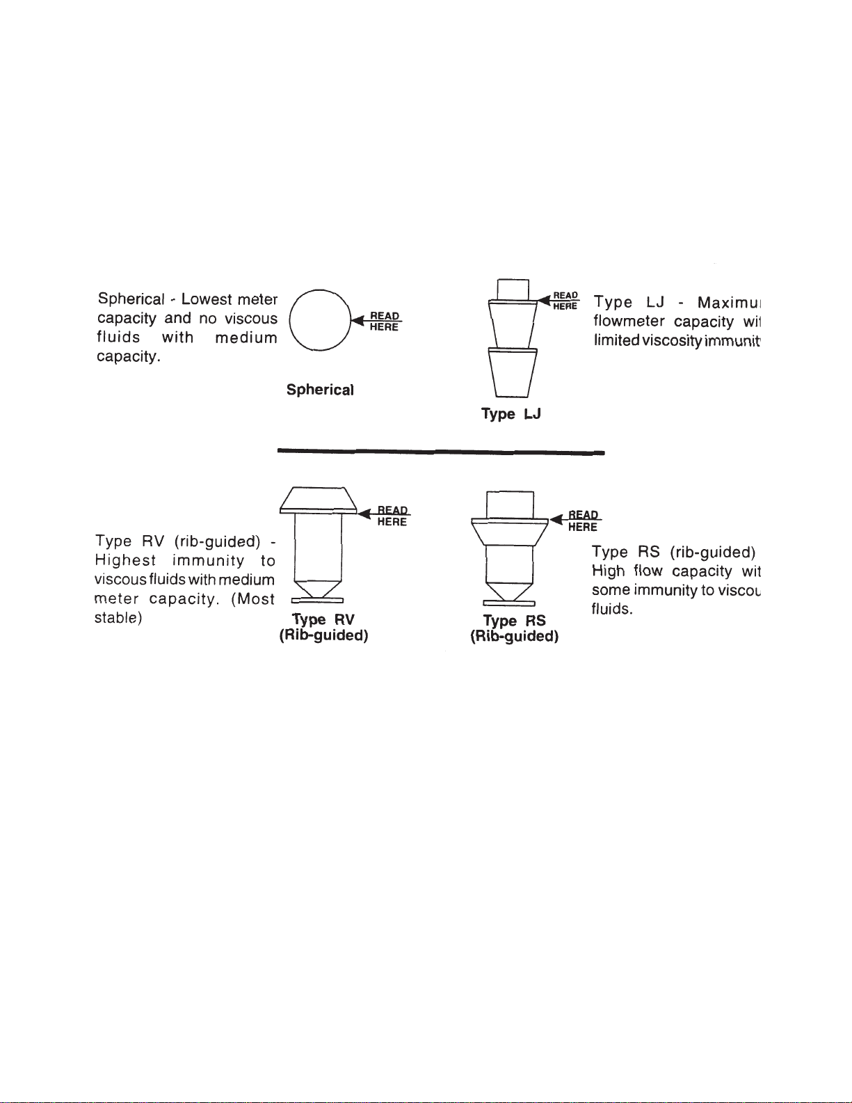
There are four types of floats available for the flowmeter. Refer to figure 1-3. The following
description refers to floats used in the same size tube. The spherical float is the least costly,
however, it has the lowest capacity and offers no viscosity immunity. The RV viscosity
compensating float offers the greatest immunity form viscosity and still greater flow rate. The
RS semi-compensating float gives higher capacity than the RV float, however, it is not as
viscosity compensating. The LJ float offers the maximum capacity available in a given tube
size however, it is less viscosity compensating than the RS float.
Figure 1-3. Float Types
Guide ribs are formed into the tube to keep the float operating in the center of the tube (refer to
Figure 1-2). The guide ribs do not follow the taper of the tube. They are parallel to the tube
centerline so that the proper operating clearance for the float is maintained for its entire range
of travel. As you can see from Figure 1-2, the increasing annular area of the tube is in the area
between the ribs.
A scale is mounted on the flowmeter to enable reading the height of the float above the zero
reference as a percent of full scale. A factor tag is supplied which provides a constant that can
be used to convert readings to actual flow rate units.
2
Page 6

Figure 1-4. FL1650/1660 Series Dimensions
3
Page 7

1-3 FACTORS THAT AFFECT OPERATION
Specific gravity is the ratio of the density of a given substance to that of a constant substance,
usually air or water. As the specific gravity of the measured fluid increases, so does the
buoyancy of the float. For this reason, the float will rise higher for fluids with a high specific
gravity than in an equal flow of a fluid with lower specific gravity. The following mathematical
correction can be made for changes in specific gravity.
Qa = Qi sgc
sga
Where: Qa = Actual flow rate
Qi = Indicated flow rate
sgc = Specific gravity of the calibration fluid
sga = Specific gravity of the process fluid
Viscosity is a measure of fluid’s resistance to flow. High viscosity means high resistance. Low
viscosity means low resistance. For this reason, more energy will be required to move high
viscosity fluids through the piping system. A highly viscous fluid will move the float farther up
the tube than one of lower viscosity, moving at the same flow rate. This is true even when fluids have the same specific gravity.
Variable area flowmeters have a viscosity immunity ceiling (VIC) as part of their specifications.
This is the highest liquid viscosity the flowmeter can handle without affecting its accuracy. If the
liquid viscosity exceeds the VIC, the meter must be recalibrated at these conditions to insure
accuracy. When the viscosity of the liquid rises above the VIC, the capacity of the meter will decrease.
Temperature has an indirect effect on the meter’s performance, because it changes the viscosity
and specific gravity of a fluid. For liquids, the viscosity and specific gravity must be known at
the operating temperature. The capacity of the meter decreases as temperature increases. For
gases, the following mathematical corrections can be made.
Qa = Qi Tc
Ta
Where: Tc = Calibration temperature (absolute)
Ta = Actual temperature (absolute)
Qa = Actual flow rate
Qi = Indicated flow rate
Gases are easily compressed by increasing pressure, but liquids are nearly incompressible.
Therefore, pressure changes have negligible effect on meters used to measure gas flow. The
capacity of the meter increases as the absolute pressure increases. For gases, the following
mathematical corrections can be made.
Qa = Qi Pa
Pc
Where: Pa = Actual pressure (absolute)
Pc = Calibrated pressure (absolute)
Qa = Actual flow rate
Qi = Indicated flow rate
4
Page 8

Page 9

SECTION 2 INSTALLATION
2.1 UNPACKING
Remove the packing list and verify that all equipment has been received. If there are any
questions about this shipment, please call OMEGA Customer Service Department.
Upon receipt of the shipment, inspect the container and equipment for any signs of damage.
Take particular note of any evidence of rough handling in transit. Immediately report any
damage to the shipping agent.
Remove the plastic float retainer which protrudes from the outlet fitting before installing the
flowmeter.
2.2 INSTALLATION CONSIDERATIONS
A. LOCATION
For proper operation, the flowmeter must be mounted within 6 degrees of true vertical, with
the inlet connection at the bottom of the meter, and the outlet at the top. The use of a plump-bob,
level or other device to assure vertical positioning is recommended.
B. PIPING ARRANGEMENT
It is strongly recommended that the typical piping arrangement shown in Figure 2-1 be used
when installing the meter. the piping arrangement permits the meter to be isolated from the
flow for servicing or cleaning. The design of the flowmeter allows the horizontal inlet and
outlet end fittings to rotate independently of each other simply by loosening the two clamp
bolts for each end fitting at the rear of the meter. Additionally the various end fittings offer
horizontal or vertical connections or a combination of both.
NOTE
The carrier will not honor any claims unless all shipping material is saved for their
examination. After examining and removing contents, save packing material and
carton in the event reshipment is necessary.
Figure 2-1 Typical Flowmeter Piping Configuration
5
Page 10

2.3 PANEL MOUNTING
To panel mount the flowmeter, use the following procedure. Refer to Figure 2-3 for the
location of the panel mounting hole pattern.
1. Remove the four screws securing the front shield to the meter, then remove the front
shield.
2. Pull out on the plastic block holding the tube in position. Do not remove the two
screws securing it.
When removing the metering tube from the upper end fitting in the following step, do not
pull out too far or with too much force, or you may break it. Do not allow the float to fall out
of the metering tube. A damaged float will affect the accuracy of the meter. Hold the inlet
(lower) float stop in position with a finger when removing the tube.
3. Slide the metering tube up behind the plastic tube retainer until it clears the lower
end fitting. When the tube is clear of the end fitting, pull out on it until you can
remove it from the upper end fitting.
4. Remove the four socket head screws on the rear of the body casting, then remove the
end fittings and their clamps.
5. Drill four 5/16 holes in the body casting at the cast-in drill marks. These holes align
with the panel mounting hole pattern in Figure 2-3.
6. Install the end fitting and their clamps. Align horizontal end fittings with the piping
before tightening the clamp bolts to 95 inch/pounds.
7. Bolt the meter to the panel using four 1/4-20 bolts of a proper length for the panel
thickness.
8. Slide the metering tube onto the upper end fitting. Insure that the plastic tube
retainer is pulled all the way out. Refer to figure 2-2 to insure that the orientation of
the float is correct and that the inlet and outlet float stops are in position.
9. Push the meeting tube in and down to seat it on the lower end fitting.
10. Push the plastic tube retainer in to hold the tube in position.
Before installing the front shield, you may wish to clean the inside surface. If necessary, use
a commercial glass cleaner or mild soap and water solution to clean it. DO NOT ATTEMPT
TO CLEAN THE SHIELD WITH A DRY CLOTH, AS THIS MAY SCRATCH THE SURFACE.
11. Install the front shield on the meter and secure with four screws tightened to
35 inch/pounds.
6
Page 11

Figure 2-3. Drill Template for Front Panel Mounting (Full Scale)
7
Page 12

SECTION 3 OPERATION
WARNING
Glass metering tubes are designed for operation up to the maximum
operating pressures and temperatures as specified. Due to the inherent brittle
characteristics of glass, tube breakage could result below specified operating
conditions. Possible glass tube breakage presents a potential hazard to operating
personnel, therefore, operator protection should be supplied where operating
pressures may exceed 50 psig. A customer supplied safety shield constructed of 1/2
inch acrylic plastic may be used or the glass tube meter may be replaced with an all
metal (armored) meter.
3.1 PRE-OPERATIONAL CHECK
Prior to initial start-up and each time the flowmeter is reassembled, the zero alignment
should be checked. If the zero line on the tube is aligned with the zero line on the scale, the
flowmeter is ready for operation. If the zero lines are not aligned, loosen the screws securing
the scale and move it until the marks are in alignment. Then tighten the screws.
3.2 OPERATING PROCEDURE
CAUTION
To initiate flow through a flowmeter using bypass piping, refer to Figure 2-1
1. Close flowmeter isolation valves (A) and (B).
2. Fully open bypass valve (C) and slightly open control valve (D).
3. Initiate process flow. When flow has stabilized, fully open isolation valve (B), then
slowly open isolation valve (C).
4 Close bypass valve (C).
5. Regulate process flow using control valve (D).
6. If meter is left in bypass configuration, open drain valve (E) to prevent tube damage
caused by thermal expansion of the process liquid.
CAUTION
Failure to drain the flowmeter when isolated in a bypass loop may result in tube
breakage caused by thermal expansion of the process liquid.
When initiating flow through the flowmeter, insure that the process flows begins
slowly and evenly, without pressure surges. Surges may drive the float against
the outlet float stop, resulting in damage to the tube or float.
8
Page 13

SECTION 4 MAINTENANCE
The following procedure may be used for cleaning the tube, float and end fittings.
1. Remove the four screws securing the float shield to the meter, then remove the front
shield.
2. Slide out the plastic tube retainer holding the tube in position, to the limit of its trav-
e l
Do not remove the two screws securing it.
When removing the metering tube from the upper fitting in the following step, do not pull
out to far or with too much force on the tube, or you may break it. Do not allow the float to
fall out of the metering tube. A damaged float will affect the accuracy of the meter. Hold the
inlet (lower) float stop in position with a finger when removing the tube.
3. Slide the metering tube up behind the plastic tube retainer until it clears the lower end
fitting. When the tube is clear of the end fitting, pull on it until you can remove it
from the upper end fitting.
4. Remove the outlet float stop, float and inlet float stop from the metering tube.
5. Clean the metering tube, float stops, float end fittings with a suitable solvent.
6. Install the inlet float stop into the metering; hold in position with a finger. Refer to
Figure 2-2 for the correct orientation of the float. Slide the float into the metering tube
from the outlet end. Replace the outlet float stop in the metering tube.
7. Slide the metering tube onto the upper end fitting. Insure that the plastic tube
retainer is pulled all the way out.
8. Push the metering tube in and down to seat it on the lower end fitting.
9. Push the plastic tube retainer all the way in to hold the tube position
Before installing the front shield, you may wish to clean the inside surface. If necessary, use
a commercial glass cleaner or mild soap and water to clean it. DO NOT ATTEMPT TO
CLEAN IT WITH A DRY CLOTH, AS THIS MAY SCRATCH THE SURFACE.
10. Install the front shield on the meter and secure with four screws tightened to
35 inch/pounds.
9
Page 14

SCALE: Arbitrary 10 to 100%, 250 mm length
ACCURACY: ± 2% full scale
REPEATABILITY: ± 0.5% full scale
TEMP. RATING: 200°F for liquid, 250°F for gas
END FITTINGS: Brass std; 316 SS optional
GLASS TUBE: Borosilicate glass
FLOAT STOPS: 316 stainless steel spring wire
FLOATS: Glass for FL1651, 316 SS all others
O-RINGS: Viton std; Buna N optional
HOUSING: Die cast aluminum alloy 380, not wetted
TUBE RETAINER: ABS, not wetted
THREADED FASTENERS: 18-8 stainless steel, not wetted
SHIELD: Polycarbonate, not wetted
CONNECTION: 3/4” FNPT, Horizontal
WEIGHT: 8.0 lbs; 3.63 kg.
DIMENSIONS: 4.25”W, 3.5”D, 19”H, 17.5” centerline port-to-port
Model
No.
Maximum Working Pressure
(PSIG) up to 200° F
All Applications
Pressure Reduction
Above 200° F
PSI/°F
Maximum Working Pressure
(PSIG) up to 250° F
Gas Applications
FL1651,1652
FL1653-6
FL1657,1658
FL1659,60,61
350
300
240
200
312.5
262.5
210.0
177.5
0.75
0.75
0.60
0.45
TABLE 5-2
RECOMMENDED WORKING PRESSURE RATINGS
TABLE 5-1
CAPACITIES
SECTION 5 SPECIFICATIONS
10
Page 15

S.G. X (O.T. + 460)
11
Page 16

WARRANTY/DISCLAIMER
OMEGA ENGINEERING, INC. warrants this unit to be free of defects in materials and workmanship for a
period of 13 months from date of purchase. OMEGA’s WARRANTY adds an additional one (1) month
grace period to the normal one (1) year product warranty to cover handling and shipping time. This
ensures that OMEGA’s customers receive maximum coverage on each product.
If the unit malfunctions, it must be returned to the factory for evaluation. OMEGA’s Customer Service
Department will issue an Authorized Return (AR) number immediately upon phone or written request.
Upon examination by OMEGA, if the unit is found to be defective, it will be repaired or replaced at no
charge. OMEGA’s WARRANTY does not apply to defects resulting from any action of the purchaser, including but not limited to mishandling, improper interfacing, operation outside of design limits,
improper repair, or unauthorized modification. This WARRANTY is VOID if the unit shows evidence of
having been tampered with or shows evidence of having been damaged as a result of excessive corrosion;
or current, heat, moisture or vibration; improper specification; misapplication; misuse or other operating
conditions outside of OMEGA’s control. Components which wear are not warranted, including but not
limited to contact points, fuses, and triacs.
OMEGA is pleased to offer suggestions on the use of its various products. However,
OMEGA neither assumes responsibility for any omissions or errors nor assumes liability for any
damages that result from the use of its products in accordance with information provided by
OMEGA, either verbal or written. OMEGA warrants only that the parts manufactured by it will be
as specified and free of defects. OMEGA MAKES NO OTHER WARRANTIES OR
REPRESENTATIONS OF ANY KIND WHATSOEVER, EXPRESS OR IMPLIED, EXCEPT THAT OF TITLE,
AND ALL IMPLIED WARRANTIES INCLUDING ANY WARRANTY OF MERCHANTABILITY AND
FITNESS FOR A PARTICULAR PURPOSE ARE HEREBY DISCLAIMED. LIMITATION OF
LIABILITY: The remedies of purchaser set forth herein are exclusive, and the total liability of
OMEGA with respect to this order, whether based on contract, warranty, negligence,
indemnification, strict liability or otherwise, shall not exceed the purchase price of the
component upon which liability is based. In no event shall OMEGA be liable for
consequential, incidental or special damages.
CONDITIONS: Equipment sold by OMEGA is not intended to be used, nor shall it be used: (1) as a “Basic
Component” under 10 CFR 21 (NRC), used in or with any nuclear installation or activity; or (2) in medical
applications or used on humans. Should any Product(s) be used in or with any nuclear installation or
activity, medical application, used on humans, or misused in any way, OMEGA assumes no responsibility
as set forth in our basic WARRANTY/ DISCLAIMER language, and, additionally, purchaser will indemnify
OMEGA and hold OMEGA harmless from any liability or damage whatsoever arising out of the use of the
Product(s) in such a manner.
RETURN REQUESTS/INQUIRIES
Direct all warranty and repair requests/inquiries to the OMEGA Customer Service Department. BEFORE
RETURNING ANY PRODUCT(S) TO OMEGA, PURCHASER MUST OBTAIN AN AUTHORIZED RETURN
(AR) NUMBER FROM OMEGA’S CUSTOMER SERVICE DEPARTMENT (IN ORDER TO AVOID
PROCESSING DELAYS). The assigned AR number should then be marked on the outside of the return
package and on any correspondence.
The purchaser is responsible for shipping charges, freight, insurance and proper packaging to prevent
breakage in transit.
FOR W
ARRANTY RETURNS, please have the
following information available BEFORE
contacting OMEGA:
1. Purchase Order number under which the product was PURCHASED,
2. Model and serial number of the product under
warranty, and
3. Repair instructions and/or specific problems
relative to the product.
FOR NON-WARRANTY REPAIRS,
consult OMEGA
for current repair charges. Have the following
information available BEFORE contacting OMEGA:
1. Purchase Order number to cover the COST
of the repair,
2. Model and serial number of the product, and
3. Repair instructions and/or specific problems
relative to the product.
OMEGA’s policy is to make running changes, not model changes, whenever an improvement is possible. This affords our
customers the latest in technology and engineering.
OMEGA is a registered trademark of OMEGA ENGINEERING, INC.
© Copyright 2001 OMEGA ENGINEERING, INC. All rights reserved. This document may not be copied, photocopied, repro-
duced, translated, or reduced to any electronic medium or machine-readable form, in whole or in part, without the prior
written consent of OMEGA ENGINEERING, INC.
 Loading...