

Page 1
OMEGA
An
One Omega
Stamford,
Group Company
Drive, Box
CT 06907-0047
(203)359-1660
4047
Telex: 996404 Cable: OMEGA FAX: (203) 359-7700
FL-1600 SERIES
ROTAMETERS
)CAUTION/
It is recommended that this publication be read in its entirety before performing any operation. Failure to understand and follow these
irWUCtiOnS
could result in serious personal injury and/or damage to the equipment.
SECTION 1 INTRODUCTION
1.1
GENERAL DESCRIPTION
The OMEGA@ Series FL-1600 Rotameters are variable
area flowmeters designed for general in-line and by-pass
metering applications where operating conditions are
within the limitations of glass metering tubes.
A float is free to travel up and down within a tapered
borosilicate glass tube. As the float rises a greater flow
area exists: as it descends, flow area decreases. Fluid
flowing through the flowmeter (from bottom to top)
causes the float to rise to a point of dynamic balance,
which is a true indication of the flow.
1. 2
SPECIFICATIONS
CAUTiOq
1
Do not operate this instrument in excess of specifica-
tions listed below.
PRESSURE RATINGS:
FL-1604
FL-1605 100
FL-1606
L
FL-1607
NOTES:
1.
Pressure ratings are based on
2.
Above pressure
3. Maximum safe working pressures for glass tubes above 200 degrees F can be
calculated by
Caution: Do not use meters in excess of these pressures.
??
All plastic or
psig at 75 degrees F.
CONNECTIONS:
(
rattngs
using
non-metallic
Model
75
100
statrc
apply to rib or plain tapered tubes.
the pressure reduction given in the table above.
pressure applicable at 200 degrees
havea maximum safe pressure rating of 100
meters
&
Inlet
FL-1601
FL-1602
FL-1603
FL-1604
FL-1605
FL-1606 1
I
FL-1607
I
54
4L
%
%
1
400 0.45
400 0.33
400
Outlet
(NPTlHoriz.
”%
”
”
”
I
81
Outlet
Inlet
Vertical
?4
1”
‘/1
2”
0.25
(NPT)
”%
*
”
”1
F.
ACCURACY
*2%
INDUSTRIAL:
of full scale from 100% to 10% of scale
reading.
tl%
CALIBRATED:
of full scale from 100% to 10% of scale
reading.
%
% full scale.
t
REPEATABILITY: Within
MATERIALS OF CONSTRUCTION
METERING TUBE:
6OTOSiliCStS
glass
FLOATS: 316SS
FD-TINGS:
END
PACKING MATERIAL: Neoprene (brass meters); Teflon
Brass or 316SS
(316SS
meters)
O-RINGS:
Buna-N
SIDE PLATES: Aluminum
GLAND RINGS: Steel
GUIDE RODS, CARTRIDGES: 316SS
SAFETY GLASS WINDOWS: Aluminum Frames
GLAND
FOLLDWERS:
SCALE: 250 mm, detachable metal plate,
Aluminum
lo%-100% of FS
SECTION 2 INSTALLATION
RECOMMENDED INSTALLATION PRACTICES
Water hammer and surges can be damaging to any
flowmeter and must
always be avoided.
Water hammer occurs when a liquid flow is suddenly
stopped as with quick closing and solenoid operated
valves. Surges occur when flow is suddenlv begun, as
when a pump is turned on at full power or a valve is quick-
ly opened.
Liquid surges are particularly damaging to flowmeters if the
surqes.
pipe is originally empty. To avoid damaging
fluid
lines should remain full (if possible) and pumps should be
brought up to power slowly and valves opened slowly. In
addition, to avoid both water hammer and surges, a surge
chamber should be installed.
I
2.1
RECEIPT OF EQUIPMENT
When the equipment is received, the outside packing
case should be checked for any damage incurred during
shipment. If the packing case is damaged, the local car-
rier should be notified at once regarding his liability.
Remove the envelope containing the shipping list.
Carefully remove the equipment from the packing case
and inspect for damaged or missing parts. Be sure the
float is not accidentally discarded with the packing, as
some larger meters are shipped with the iioat
remcved
from the tube to prevent breakage
2. 2
RETURN SHIPMENT.
Do not return any merchandise without an Authorized
Return (AR) number. Call OMEGA Customer Service
Department at (203) 359-1660.
2. 3
I
INSTALLATION OF FLOAT
Some flowmeters are shipped with the float installed in
the metering tube; others are shipped with the float
_.
I
.:
packed separately to prevent possible damage during
shipment and handling. In either case, remove the wrap-
pings and/or other protective material. Take great care to
avoid damaging the float. The accuracy of the meter
depends upon the float remaining dimensionally and
gravimetrically stable.
Page 2
!.4
It is advisable to insert the float before the flowmeter is
installed in the line Where the vertical inlet and outlet are
used for piping connections this is absolutely necessary.
Use reasonable care in inserting the float. Don ’t
justdrop
it in the glass metering tube. A sheet of paper slightly
coiled, forms a convenient chute so the float can be slid
into the metering tube avoiding high impact.
To install free or ribbed tube floats, remove the bottom
cleanout
plug (or flanged cover) and take out the bottom
float stop. Place the float in the tube with a paper chute,
as described above, and replace the float stop and
cleanout
plug.
With rod guided floats, take great care not to bend the
guide rod. Should the guide rod become bent, or its
polished surface become marred by burrs, scratches or
accumulation of foreign matter, it is advisable to replace
it with a new one. Never attempt to straighten a bent
guide rod.
Rod guided floats are inserted at OMEGA and are shipped
with a wooden dowel protector preventing undue move-
ment of the float while the rotameter is in transit. Be sure
to remove the wooden dowel before installing the
rotameter.
To install rod-guided floats, remove both top and bottom
cleanout
plugs. Remove the top nuts on the guide rod and
remove the guide rod and guide rod cartridge through the
bottom opening of the meter. Place the float on the guide
rod and put it back in the tube. Guide rod nuts should be
tightened until the guide rod is tensioned. If the guide is
not sufficiently tightened, there may be a tendency of the
float to whip under flow conditions. Replace the
cleanout
plugs (or flanged cover).
LOCATION OF CONTROL VALVE
Location of the control valve depends on many variables.
On most applications, the flowmeter will operate properly
with the control valve on either the upstream or
downstream side.
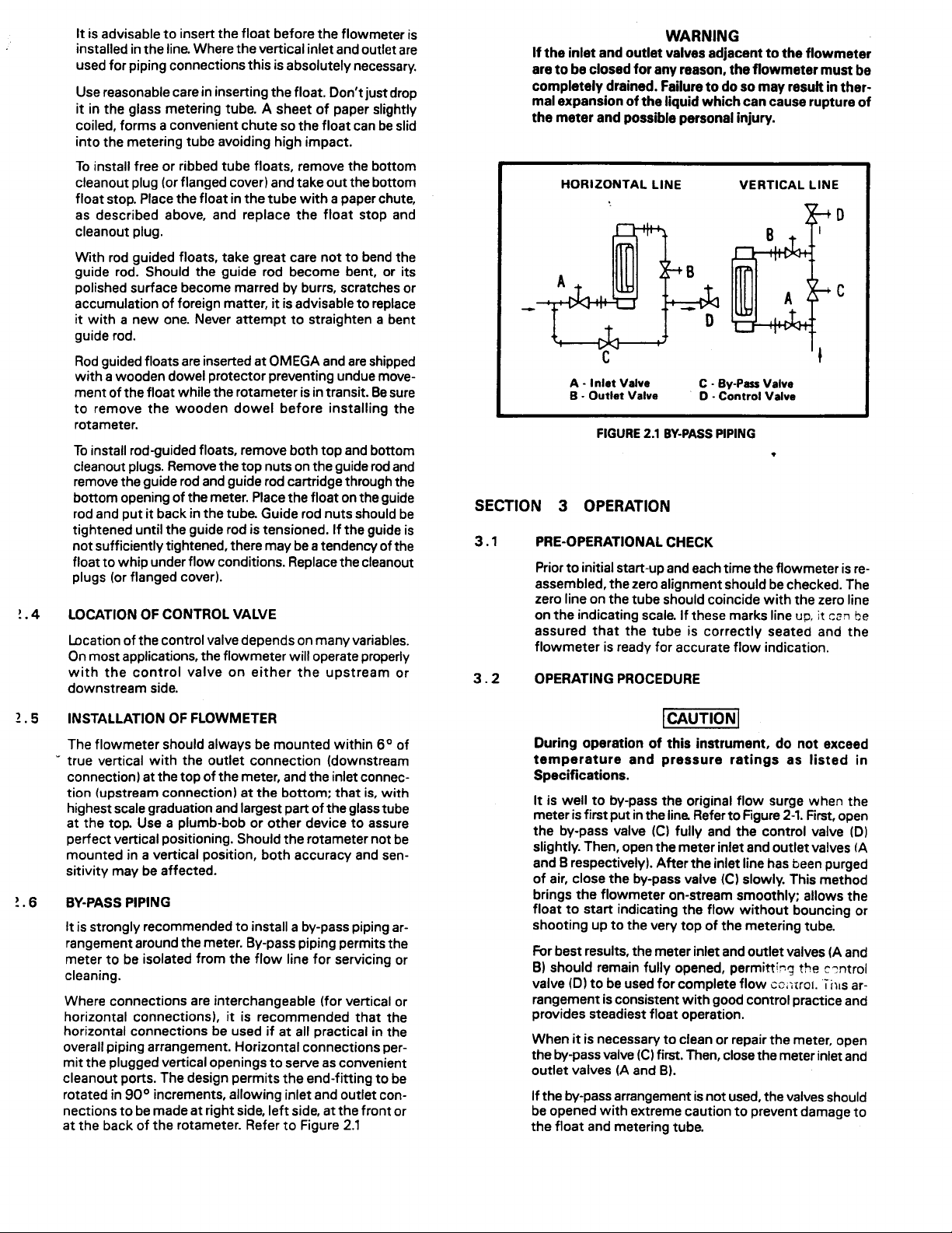
If the inlet and outlet valves adjacent to the flowmeter
are to be closed for any reason, the flowmeter must be
completely drained. Failure to do so may result in ther-
mal expansion of the liquid which can cause rupture of
the meter and possible personal injury.
HORIZONTAL
A
-
Inlet Valve
-
Outlet Valve
B
FIGURE 2.1 BY-PASS PIPING
SECTION 3 OPERATION
3.1
3. 2
PRE-OPERATIONAL CHECK
Prior to initial start-up and each time the flowmeter is re-
assembled, the zero alignment should be checked. The
zero line on the tube should coincide with the zero line
on the indicating scale. If these marks line up,
assured that the tube is correctly seated and
flowmeter is ready for accurate flow indication.
OPERATING PROCEDURE
WARNING
LINE
VERTICAL LINE
-
By-Pm
C
-
Control Valve
D
Valve
be
cm
it
the
2.5
INSTALLATION OF FLOWMETER
The flowmeter should always be mounted within
.
true vertical with the outlet connection (downstream
connection) at the top of the meter, and the inlet connec-
tion (upstream connection) at the bottom;
highest
scale graduation and largest part of the glass tube
at the top. Use a plumb-bob or other device to assure
perfect vertical positioning. Should the rotameter not be
mounted in a vertical position, both accuracy and sen-
sitivity may be affected.
!.6
BY-PASS PIPING
It is strongly recommended to install a by-pass piping
rangement around the meter. By-pass piping permits the
meter to be isolated from the flow line for servicing or
cleaning.
Where connections are interchangeable (for vertical
horizontal connections), it is recommended that the
horizontal connections be used if at all practical in the
overall piping arrangement. Horizontal connections per-
mit the plugged vertical openings to serve as convenient
cleanout
rotated in
ports. The design permits the end-fitting to be
90°
increments, allowing inlet and outlet con-
nections to be made at right side, left side, at the front or
at the back of the rotameter. Refer to Fiaure 2.1
that
6O
of
is, with
ar-
or
During operation of this instrument. do not exceed
temperature and pressure ratings as listed in
Specifications.
It is well to by-pass the original flow surge when the
meter is first put in the line Refer to Figure 2-l. First, open
(C)
the by-pass valve
fully and the control valve
slightly. Then, open the meter inlet and outlet valves
(D)
(A
and B respectively). After the inlet line has been purged
(C)
of air, close the by-pass valve
slowly. This method
brings the flowmeter on-stream smoothly; allows the
float to start indicating the flow without bouncing or
shooting up to the very top of the metering tube.
For best results, the meter inlet and outlet valves (A and
B) should remain fully opened,
(D)
valve
to be used for complete flow
permitt+
cc‘itror.
the
c-ntrol
T;IIS
ar-
rangement is consistent with good control practice and
provides steadiest float operation.
When it is necessary to clean or repair the meter, open
the by-pass valve
outlet valves
(C)
first. Then, close the meter inlet and
(A
and B).
If the by-pass arrangement is not used, the valves should
be opened with extreme caution to prevent damage to
the float and metering tube.
Page 3

SECTION 4 MAINTENANCE
4.1 CLEANING
When the recommended horizontal connections are us-
ed, the flowmeter may be cleaned in this manner:
1.
Remove top and bottom
2 .
Remove the float and float stops. Be careful not to
damage the float.
Swab out the metering tube and end fittings with a
3 .
suitable solvent.
Replace float, float stops. and
4 .
flanges).
4. 2
DISASSEMBLY
1.
Remove front and back windows and window
frames.
Completely unscrew gland bolts from top and bot-
2.
tom end fittings.
Remove cap screws from the side plates of the top
3.
end fittings.
4.
Loosen the cap screws in the bottom end fitting so
that the side plates may be spread apart to allow the
top and bottom end fittings to be removed.
The metering tube may now be removed.
5.
4. 3
REASSEMBLY
1.
Replace the tube, being careful to see that the outlet
(wide) end of the tube fits flush against the tube seat
gasket in the outlet (top) end fitting.
-
cleanout
plugs (or flanges).
cleanout
plugs (or
Replace the windows and window frames. The seal-
5.
ing gaskets on the windows should be placed face
down against the meter body. Tighten the shield
bolts on the window frame only until they are
“snug,” then tighten one-quarter additional turn.
After the flowmeter has been re-assembled, it is im-
6.
portant that it be hydrostatically tested at the liquid
pressure rating as shown in the Hydrostatic Test
Pressure Table.
Hydr&&ic
testing should be performed only by
trained and qualified personnel or serious
damage could result.
HYDROSTATIC
TABLE 4-l.
TEST PRESSURES
Max. Working
Model
FLil601, 1602
FL-1603
FL-1604,
FL-1
1605
606
Pressure (PSI)
200°F
at
300
175
100
FL1607 100
75
’
Hydrostatic Test
Pressure
(PSI)
450
260
150
110
150
NOTE
Because both Teflon hat gaskets are purposely tight
fitting, they can be more easily assembled from the
inlet (smaller) end of the tube The smaller (inlet end)
gasket is often difficult to place over the glass tube.
A suggested method is to place the hat gasket in the
gland ring on a horizontal surface and carefully force
the end of the tube through the gasket and ring. This
will stretch the gasket enough that it can be removed
and reassembled on the tube in the proper order.
Im-
mersing the gaskets in warm water will further in-
crease their elasticity and help prevent damaging
them, particularly in cold weather. If the outlet
gasket on the larger tubes seems unable to be mov-
ed into position when being driven by the packing
ring, a small amount of silicone lubricant may be
used.
2. Since the dowel-pin construction assures perfect
alignment of the frame assembly, merely tighten the
cap screws to attach the side plates to the end
fittings.
3. Insert the packing gland bolts. Tighten the gland
follower on the “seating end fitting” before tighten-
ing the gland follower on the other end fitting. The
“seating end fitting” is always the outlet (top) end
fifing. If this procedure of tightening the seating end
first is not followed, the tube may be pulled away
from the seat gasket and the zero line on the tube
may not show above the inlet gland follower. In
tightening the packing bolts, tighten them
diagonally.
Check the zero line on the metering tube and on the
4.
scale for exact alignment.
Type
(rib-guided)
Spherical
Aumb-Bob
Figure 3-1. Float Types
SECTION 5 PARTS LIST
When ordering replacement parts be sure to specify the
following: SERIAL NUMBER, Complete model number,
part description and quantity. Refer to Figure 5-2.
Glass metering tubes are designed for operation up to
the maximum operating pressures and temperatures as
specified herein. Due to the inherent brittle characteristic
of glass and conditions beyond our control, tube
breakage could result below specified operating condi-
tions. Possible glass tube breakage represents a poten-
tial hazard to operating personnel; therefore, operator
protection should be supplied where operating pressures
may exceed 50 psig. A safety shield construction of
inch acrylic plastic may be used or the glass tube meter
may be replaced with an all metal (armored) meter.
RS
Type GV
(rod-gurcfed)
Spool
WARNING
GS
Type
(rod-guided)
LJ
Type
%
Page 4

9
10
11
17
._
1
13
1
14
17
IfI
I
Window
I
1
19
20
I
1
Scale Blank
21
-
Follower
_..-
-
Ring
Rina
___
Seat Gasket
Phi&d
1..
...”
.
. . . .
Outlet
___.
-
Inlet
-
Outlet
lasket
3lass
(
Packing
Side Plate
Scale Side Plate
Glrnd
_._..
Gland
Gland
Window Frame
Millnrl
-----~-
FrameGasket
Meter Gasket
Steel
Steel
steot
_...“.
,
-
,
1
1
1
Steel
Steel
1
Asbestos
Asbestos
Stn. Stl.
Stn. Stl.
Safety Felt
Cork
1
I
I
1 I Aluminum
Glass
Figure 5-2. Parts Drawing
WARNING
FLOWMETER OPERATION
If the inlet and outlet valves adjacent to the flowmeter are to be closed
”
for any reason, the flowmeter must be completely drained. Failure to do
so may result in thermal expansion of the liquid which can cause rupture
of the meter and possible personal injury.
HORIZONTAL LINE
No. 6 Plain
28
29
t 30 I Stuffino Box Aina
31
32
33
35
34
36 Cartridge Gasket
37
38
39
Scale Holder Screws
Hd. Self-Tapping
Scale Holder Screws
Hd. Self-Taopina
Stuffing
Guide Rod
Guide Rod
I
Cartridae
1
Cartridge
Cartridge Gasket.
Teflon Hat Gasket
Teflon Hat Gasket
80x
-
-
Outlet
Inlet
. .
Ring
VERTICAL LINE
_
-
inlet
-
Outlet
Inlet
-
Outlet
-
Inlet
-
Outlet
-
Oval
Rd.
2 Stn. Stl.
2
7
1
I
1
1
2
I
1
1
1
1
1
1
1
Stn. Stl.
Stn. Stl.
I
I
I
I
COPYRIGHT 1987 OMEGA ENGINEERING, INC. PRINTED IN U.S.A.
-
Inlet Valve
A
-
Outlet Valve
B
-
Bypass Valve
C
-
Control Valve
D
TYPICAL INSTALLATION
M379/097
 Loading...