

Now Available
COMPUTERIZED
FLOW TABLES
FL-1 00 SERIES, FL-1 10, FL-1 20
FOR OMEGA@
L
D
project at Omega Instruments has
R
A new
produced a new computerized procedure for
generating complete
fluid of known viscosity and density.
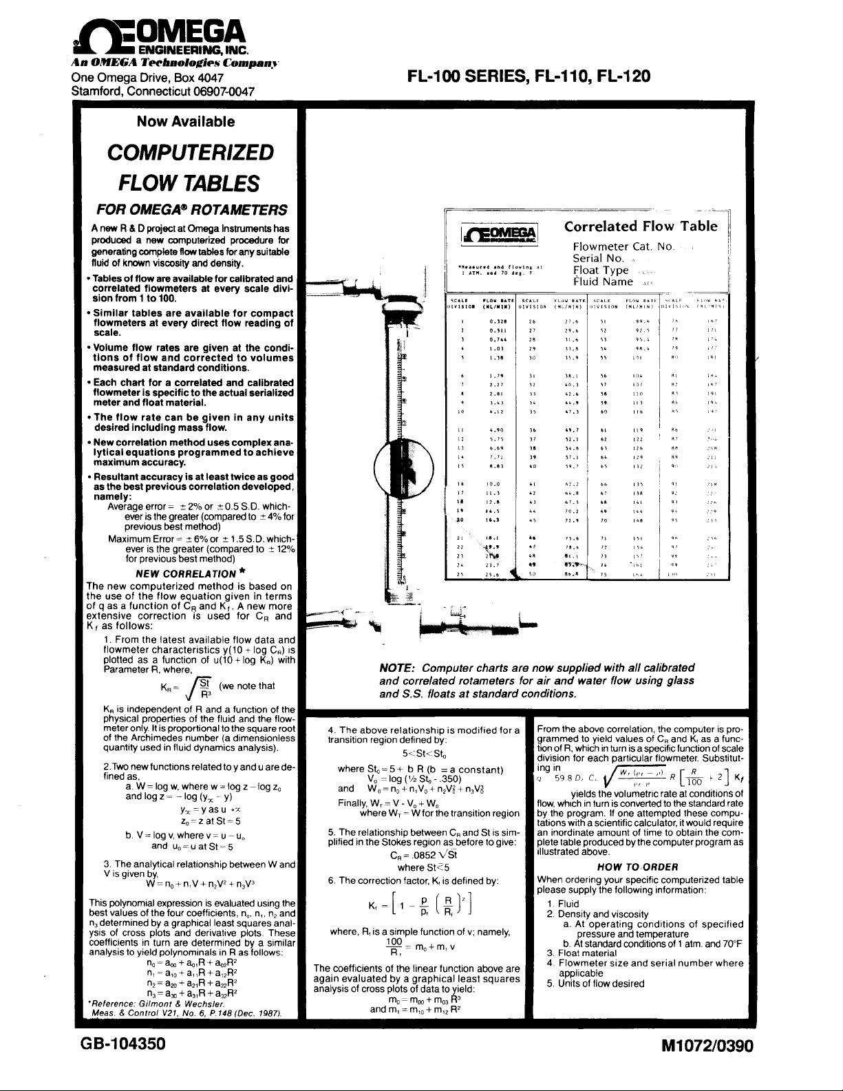
Tables of flow are available for calibrated and
correlated flowmeters at every scale divi-
sion from 1 to 100.
Similar tables are available for compact
flowmeters at every direct flow reading of
scale.
Volume flow rates are given at the
tions
of flow and corrected to volumes
measured at standard conditions.
Each chart for a correlated and calibrated
flowmeter
meter and float material.
The flow rate can be given in any units
desired including mass flow.
New correlation method uses complex
lytical
maximum accuracy.
Resultant accuracy is at least twice as good
as the best previous correlation developed,
namely:
‘he new computerized method is based on
he use of the flow equation given in terms
!xtensive
cf
as follows:
is specific to the actual serialized
equations programmed to achieve
Average error =
ever is the greater (compared to
previous best method)
Maximum Error =
ever is the greater (compared to
for previous best method)
NEW
correction is used for
1. From the latest available flow data and
flowmeter characteristics
plotted as a function of
Parameter Ft. where,
ROTAMETERS
Row tables
-t
2% or
-t
CORRELATION *
CR
f
6% or
and If q as a function of
~(10
for any suitable
0.5 S.D. which-
K, A new more
~(10
-+
SD.
CR
+
log C,)
+
log K,) with
condi-
ana-
4% for
which-
2 1.5
-+
12%
and
IS
function of the
R
IS
independent of
KR
physlcal
properties of the fluid and the
meter only. It is proportional to the square root
of the Archimedes number (a dimensionless
quantity used in fluid dynamics analysis).
2.Two
new functions related toy and u are
fined as,
a. W = log
and log z
b.V=logv,wherev=u-u,
and
3. The analytical
V is given by,
This
best values of the four coefficients,
n3
determined by a graphical least squares anal-
ysis of cross plots and
coefficients
analysis to yield
‘Relerence:
Meas.
W =
polynomial expression is evaluated
In
turn are determined by a similar
n,=a,+q,R+q2R2
=a,,+a,,R+a,,RZ
n,
n3
= a, +
Gitmont
8
Control
and a
w.
where w = log z log
-
log (y, y)
=
y,=yasu
z,=zatSt=5
u,=uatSt=5
relatlonship between W and
n,
+
a,,R
aZO
n2 =
a,,R +
Wechster.8
V21,
No.
a=
n,V3
i n,V*
n,V +
derivattve plots These
R
as follows:
In
polynominals
a&+
+ +
aZ2RZ
6,
P.148 (Dec. 1987).
GB-104350
using
n,. n,.
n2
flow-
z0
the
and
de-
5. The relationship between
plified in the Stokes
6. The correction factor,
R,
is a simple function of
where,
The coefficients of the linear function above are
again evaluated by a graphical least squares
analysis of cross plots of data to yield:
and
region as before to
St<5
where
K,
m,=m,+m,,RJ
m,
mrp
=
is defined by:
namely,
v;
R2
m,, +
IS
give:
division
ingi;98D,
whfch
flow,
by the program. If one attempted these compu-
tations with a scientific calculator, it would require
an inordinate amount of time to obtain the
sim-
C, and St
plete table produced by the computer program as
illustrated above.
ordenng your specific computerized table
When
please supply the following information:
a. At
b. At standard conditions of 1 atm. and 70°F
3. Float material
4. Flowmeter
5.
Units of flow desired
particular flowmeter.
for each
4-R
C,
in turn is converted to the standard rate
TO,ORDER
IiOW
operating
pressure and temperature
conditions of
condltlons ofvolumetnc rate at yields the
072/0390
Ml
Substitut-
21
K ,
+
[A
com-
specified
wheresize and serial number
OMEGA@
ROTARilETERS
iIGH-ACCURACY, UNSHIELDED
??
Computer tables are now included at no extra charge
-
four tables in ail, air and water at standard condi-
tions using glass and stainless steel floats. For other
fluids and any conditions of flow.
??
The standard calibration chart for air and water using
the glass float now contains the values of
with the new generalized correlation.
??
Calibration curves for any fluid and float can be
obtained at the
operating
conditions of flow using
the new generalized correlation. Only the density and
viscosity of the fluid need be known.
??
Each serialized meter is statistically calibrated with
air at three points (an improvement over the previous
two point calibration) to assure an accuracy of
f
1 Scale division (whichever is the greater).
or
. Readings are reproducible to
divisions (whichever is the greater).
??
Other features have been maintained as follows:
1. Specially designed Teflon stops accept cones.
ponding tapered joints and O-Rings to make a
vacuum tight seal.
2. Permanent black ceramic scale and white
background for easy reading.
3. Corrosion resistant-fluid comes in contact with
f
1% or
glass and tefion only (when using glass float and
plain end meter).
4. Glass and stainless steel floats are supplied with
each meter. A conversion chart indicates pressure
drops for each float and converts flow rates with the
glass float to those with stainless steel.
These flowmeters are manufactured from tapered
precision bore tubing to ultimate tolerances
.0002’)
which give maximum precision attainable
for spherical float rotameters.
The tolerances on
the floats are of comparable magnitude.
The latest generalized correlation is based on a new
dimensionless
number). Prediction of fluid flows with an accuracy at
least twice as good as any previous method is now
possible (see page 1). See DIRECTIONS of sample
calculations using graphical and analytical methods.
*
U.S.
Patent No.
**
Reference:
p.2070
Reference:
p.148
SIZE N
Description
.etlan
Stop, Top
retIon
Stop. Bottom
:lowmeter
Tube
klmt,
inner
loIni.
Outer
101 Ring 1
I-Ring
EPR
-LOAT
;1ass
;?I
166
lCttt
149 24
density,
ttt suppled
(1941).
(Dec.
O
JOl",
253
8
02
26 32
FA
and
= pf
wlfh
Gilmont
Gllmont
1987).
FwFC Pf
1
i
1 F-2032 S
18
conversion
1
3OF-2032.TC
quantityKi”(related
3,183,713
Maurer.
8
0
Cat. No.
F-2004 F-1104
F-2005 F-1105 F-1205
F-2031 F-1131
F-1133
F-1134
S-1105
S~l105-E
F-2032
magmfylng
for
char,
&
Control Sys. V.34.
Instr.
&Control V.21, N
Meas.
8 Wechsler.
Cat. No.
F-1133 F-l 233
F-1134
S-1105
S-ll05~E
F~ll32
F-1132-S
F-1132-T F-1232-T
factors far Fw are
flow and pressure drop
NOTE: Extremely dry gases,
to electrostatic charge build-up.
R
for use
f
2%
*
0.5 scale
.OOOl-
(-t
to the Archimedes
SPARE I
1
Cat.
No.
2
F~l204
F-1231
F-i 234
F-7032
F-7032-E
F-1232
F-1232~s
wakr
& ar
at low flows, may cause erratic readings due
DIRECTIONS
The procedure for calculating the flow of any fluid of known density and
viscosity are based on the new standard correlation curve supplied
with the new serialized flowmeter. NOTE: Owners of old serial
bers may write for a new
the size and serial number of the flowmeter.
1.
Select the desired value of Rat the corresponding value of
scale
division from the calibration curve supplied.
2.
Calculate the value of
where,
W,
p,
p
W,
and
note,
3.
From the correlation chart on the next page obtain the value
28
corresponding to
chart
at no extra charge, by supplying us with
GRAPHICAL SOLUTION
KR:
W ,(p:j-pipl ”l
,.;,
K,=
viscoscity
= weight of float in g/cc
=
density of float in
=
density of fluid in
P,
[
of fluid in cp= p
g/cc
Kn.
When
glee
.19.
use the equation
<
C,
are given in the calibration curve data.
R
and
.0852K,R’5C, =
4.
Determine the value of the correction factor.
<
10, the value of R values of
K, as
letermine
a. Calculate the value of
follows:
v
b. From the Correction Factor Chart on the page following thr
Correlation Chart, obtain the value of
to the values of
c. Calculate the value of
5
Calculate the volumetric rate of flow,
whers,
Kq
D, snd
= Diam. float in inches from data.
above.value of
3.
The
.educed
to a volume measured at standard conditions,
=
density at standard conditions
p0
Nhere.
O
6,
JAR1
rs LIST
Cat. No.
F-1304
F-1305
F-1331
F-1333
F-1334
S-1205
S 1205-E
F~l332
2119-S
1332-Trantttt
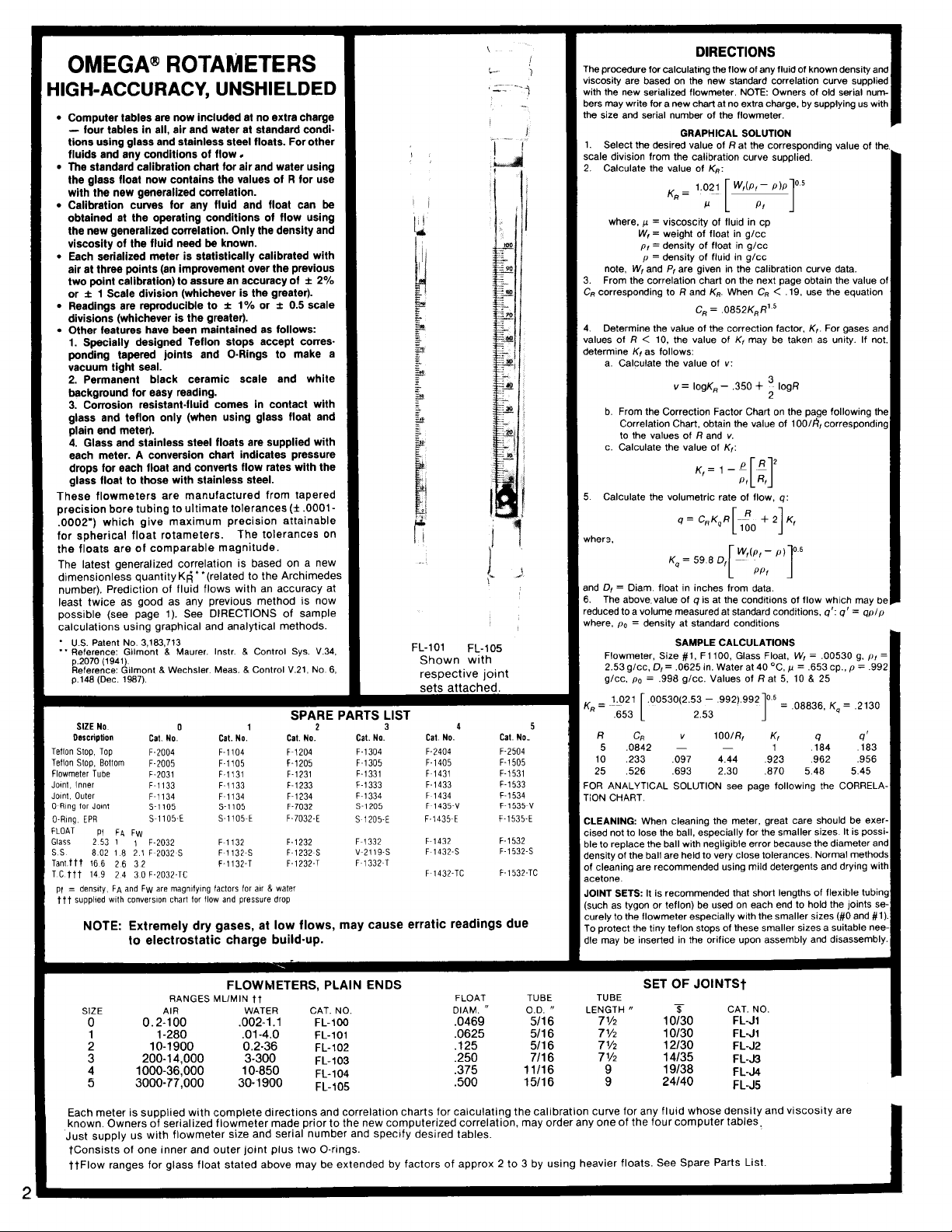
Shown with
resDective
3
FL-105
ioint
4 5
Cat. No.
F-2404 F-2504
F-1405 F-1505
F
1431
F-1433 F-1533
F
1434 F-1534
F
1435-v
F-1435E
F~l432
F
1432-S
F
1432.TC
Cat. No.
F-1531
F-1x35~”
F-1535-E
F-1532
F-1532-S
F-1532.TC
Flowmeter, Size
2.53
g/cc.
=
Ry
,653
R
.0842
5
,233
10
25
-OFI
ANALYTICAL SOLUTION see page following the
I!
r:ON CHART.
CLEANING:
sised not to lose the ball, especially for the smaller sizes It is
318
to replace the ball with negligible error because the diameter
density of the ball are held to very close tolerances. Normal method:
3f cleaning are recommended using mild detergents and drying witt
acetone.
JOINT SETS: It is recommended that short lengths of flexible
[such as tygon or teflon) be used on each end to hold the joints se
To protect the tiny teflon stops of these smaller sizes a suitable nee
dle may be inserted in the orifice upon assembly and disassembly
SAMPLE CALCULATIONS
.0625
= 0,
glee.
.99d
g/cc. Values of
p.
=
.00530(2.53
L
CR
.097
,693
When cleaning the meter, great care should be
K, may be
taken as unity. If not
v:
3
,350 t
- IogK,
=
Y.
R and
K,:
K ,= ,-- P
q=
[
q
is at the conditions of flow which
FllOO,
#l.
in. Water at 40
.992).992
-
1.021
2.53
100/R,
1
4.44
2.30,526
IOQR
2
!T2
R,PI
[I
f.
+ 2 CRK4R
[
1
‘)
!%-
D, 6 = 59
PPt
1
Glass Float,
‘C.
at
5, 10
O5
1
K,
1
.923
,870
100/k?,
q:
K,
‘s
=
=
= W,
,653
p
&
25R
.06836.
.P64
,962
5.48 5.45
num
For gases
correspondin<
may be
qpfp
q ’
=
q’:
p, g,
.00530
.99i
= p
cp.,
.2130Kq =
.%33
,956
CORRELA.
exer.
POSSi.
tubin<
(#O
and curely to the flowmeter especially with the smaller sizes
I
the
o
antK,.
=
aru
#1)
IO%0
10130
12130
14135
19138
24140
JOlNTSt
CAT. NO.
FL-J1
FL-J1
FL-J2
FL-J3
FL-J4
FL-J5
FLOWUETERS,
MLlMlN
RANGES
SIZE
0
Each meter is supplied with complete directions and correlation charts for calculating the calibration curve for any fluid whose density and viscosity are
known. Owners of serialized flowmeter made prior to the new computerized correlation, may order any one of the four computer tables,
Just supply us with flowmeter size and serial number and
tconsists
ttFlow
ranges for glass float stated above may be extended by factors of approx 2 to 3 by using heavier floats. See Spare Parts List.
AIR
0.2-100 ,002-l
l-280
10-1900 0.2-36
200s14,000
l OOO-36,000
3000-77,000
of one inner and outer joint plus two O-rings.
tt
WATER
.Ol-4.0
3-300
1 O-850
30-l 900
.l
PLAIN ENDS
CAT. NO.
FL-100
FL-101
FL-102
FL-103
FL-104
FL-105
specify
FLOAT
DIAM.
.0469
.0625
.125
,250
,375
,500
desired tables.
TUBE
O.D.
u
5116
5116
5116
7116
11116
15/16
TUBE
n
LENGTH
SET OF
w
l/2
7
‘/2
7
‘/2
7
7
%

KR
t
r
10
ORRELA
C
T/ON CHART
Density
Gases
GAS
cetylene
.ir
.mmonia
.rgon
utane
(n)
(iso)
utane
:arbon
dioxide
:arbon
monoxide
:hlorine
thane
thylene
leiium
lydrogen
lydrogen chloride
lydrogen sulfide
.rypton
lethane
lethyl
chloride
leon
litric
oxide
litrogen
litrous oxide
)xygen
‘ropane
iulfur
dioxide
:enon
Density a Viscosity of
Liquids at
LIOUID
Acetic Acid
Acetone
Anilme
Benzene
Butyl Acetate
n-butanol
4
CCI
Chlorobenzene
Chloroform
Diethyl Ether
Ethyl Acetate
Ethanol
Ethylene Br
Ethylene Cl
Ethylene Glycol
Fluorobenzene
Heptane
Methyl Acetate
Methanol
Nitrobenzene
n-octane
Propanol
Toluene
o-xylene
m-xylene
p-xylene
Aqueous Solutions
10% HCI
30%
HCI
10%
HNO,
HNO3
40%
HzSO~
10%
HsSOa
60%
a
Viscosity of
a
at
70°F
p
in
1.087
1.200
.7155
1.655
2.510
2.481
1.035
1.160
2.989
1.259
1.170
.1657
.0834
1.522
1.429
3.382
.6653
2.139
.035a
1.244
1.161
1.836
1.326
1.075
2.717
5.307
TABLE II
In
1
atm
c1
g/Li
g/mlp
1.049 1.221
1.022 4.40
1.594
1.106
1.483
1.460
1.109 19.90
1.023
1.204 2 03
in cp
.OlOl
.0181
.00986
.0221
.0076
.0076
.0148
.0174
.0133
.00913
.OlOl
.0194
.0087
.0144
.0126
.02
514
.0109
.0107
.0312
.0188
.0175
.0144
.0203
.00803
.0125
.0226
8
1 atm70°F
in cp
p
by
weight)
.32
,652
2 946
,969
,799
.58
1 20
1.72
2 256
1.15<
1.04;
1 55E
1 22E
5 90:
,790
,879
,083
,610
,714
,900
,709
898
,684
,933
791
,703
,804
867
,880
.864
861
(%
1.048
1 149 1.70;
1.054
1.247
1.066
1.499
,732
,233
,455
.79
.598
409
381
,597
,542
,590
,810
,620
,648
0.2
FOR
CR
1.0
0.7
CR-
.0852
0.4
KRR’.~
= CR < 0.19,
0.3
0.5
1.
3

CORRECT/ON
FACTOR CHART
1.
ANALYTICAL SOLUTION OF FLUID FLOW
Same as step 1 of GRAPHICAL SOLUTION on previous page
2. Same as step 2 of GRAPHICAL SOLUTION
3. Calculate
4. Determine the region of flow as follows:
5. For the turbulent region, calculate the following:
6. For the transitional region calculate the following:
7. Calculate the
8.
9.
10.
the
following:
KR2R3
a) St =
St,, = 5 +
b)
a) If St < 5 region is Stokes, skip to step 9
b) If
c) If St >
a) V =
W ,=no+n,V+n2V2+~V3
b)
where,
a)
W,
b)
c)
zc
b)
yc = 10.040 -(l/z,)
C)
CR=
d)
Determine the value of
v
a)
where,
c)
K,
For the Stokes region calculate:
c,
q =
.777R
F
5 region is transitional, skip to step 6
.Sb
5 St
St0 region is turbulent, proceed to step 5
,350
+
1.5
-.197
no
=
n,
= 1.065
n2
=
n,V,
n,,
+
log-‘W,
(w,+
log-‘(y,-
100
m,
= 4.81
m,=
’- = 1
PI
.0852(St)05
[
1
- Kn
.00418R-
t
.0189R
-
.1510R+
-
,929
.06185R.
-
,542 = n3
n2V02
+
+
V (Vas calculated in Step V, - W0 W, =
followino:
-
0.1193)
10)
(
V from step
.138-
-2.62+
* Skip to step
R
R,
[I
+2
K,
R
100
001375R*
+
.004025R2
skip to step 7
(St,, from step
.350] - S10
log[O.5 log
n3V03
+
K,as
follows:
5a)
R3
1000
R2
,369
100
(m, from step
flow at the conditions of flow:
log[log
=
V,
=
= WC
a)
= log- ’
=
log-’ V
= a)
C,K,R
(KRfrom
.000155R2
(coeff.
the same as in 5b)
=
(K,
10
8b)
step 2)IogR]
1 for gases)
5a)
3b)
SAMPLE CALCULATIONS FOR
1.
R :
.08836
=
Y:
4:
=
.00781
:“0
:n,
:“2
:
:V,
:m,
.2130
for all values
for all values of
Kn
2.
3.
St =
sr:R3a)
b)
St,: 6.805
4.
Region: Stokes
5. a) v:
W,:b)
“3
6. a)
“‘;b)
w,:
c)
w,:
a)
7.
zc:b)
Yc:c)
C,:d)
8.
a)
b)
R,:
IQ:
K,:c)
c,:a)
9.
~;“i
b)
K,
10.
,975
.0842
4.79
5
,977
,180
ANALyrCAL SOLUTION
R
a’f
7.61
12.77
transitional
1
--.1707
1.0315
-.1785
-
0765
-.6923
-.9325
-1.061 3
-1.256 5
.0554
1.495
9.371
,235
.09632
22.54
R
25
122.0
24.4
turbulent
-.1592
-.4249
-.1894
1.4519
-.3304
-1.004 3
1
.3760
3.128
9.72
,525
931
E4
::
23
138
71
The above flow (q)
11.
conditions
q = q’
p
PO
(q’)
as follows:
where,
red&d
mky
be
p.
= density at std.
to a volume measured at standard
cond
,964
-9
(1
forfiquiisR;-3.55-51.5R+2.37R2
K,‘:
I
700
.179
x0
and S.S. size * NOTE: For
[l-(k)‘]
=
for gases
11.
q ’:
R,’
Where:
5.45
addatonal Float multiply by an
K,”facior
 Loading...