

Page 1

MADE
IN U.S.A.
1 YEAR
WARRANTY
Page 2

Page 3
Location
QUICK-START OPERATING INSTRUCTIONS
This manual contains detailed operating instructions for all aspects of the
FD-400 flow instrument. The following condensed instructions are
provided to assist the operator in getting the instrument started up and
running as quickly as possible. This pertains to basic operation of the
clamp-on transducer only. If specific instrument features or an alternate
transducer style are to be used or if the installer is unfamiliar with this type
of instrument, refer to the appropriate section in the manual for complete
details.
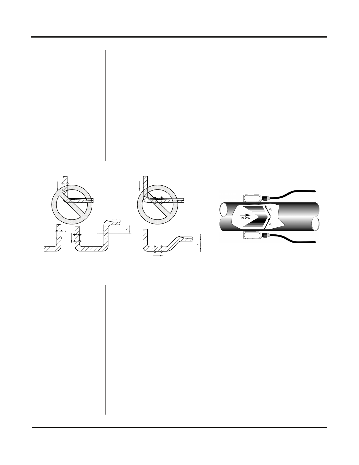
1. TRANSDUCER LOCATION
A. Determine the appropriate mounting location for the transducers by
referring to Figure 1.1. Pipe must be filled with liquid to ensure
proper operation.
Top View of Pipe
Figure 1.1
Transducer Locations
Pipe Preparation
and Mounting
2. PIPE PREPARATION AND TRANSDUCER MOUNTING
A. The piping surface, where the transducers are to be mounted,
needs to be clean and dry. Remove loose scale, rust and paint to
ensure satisfactory acoustical bonds.
B. Connect the mounting straps around the pipe. Leave the strap
loose enough to slip the transducers underneath.
C. Apply a liberal amount of silicone grease onto the transducer
faces.
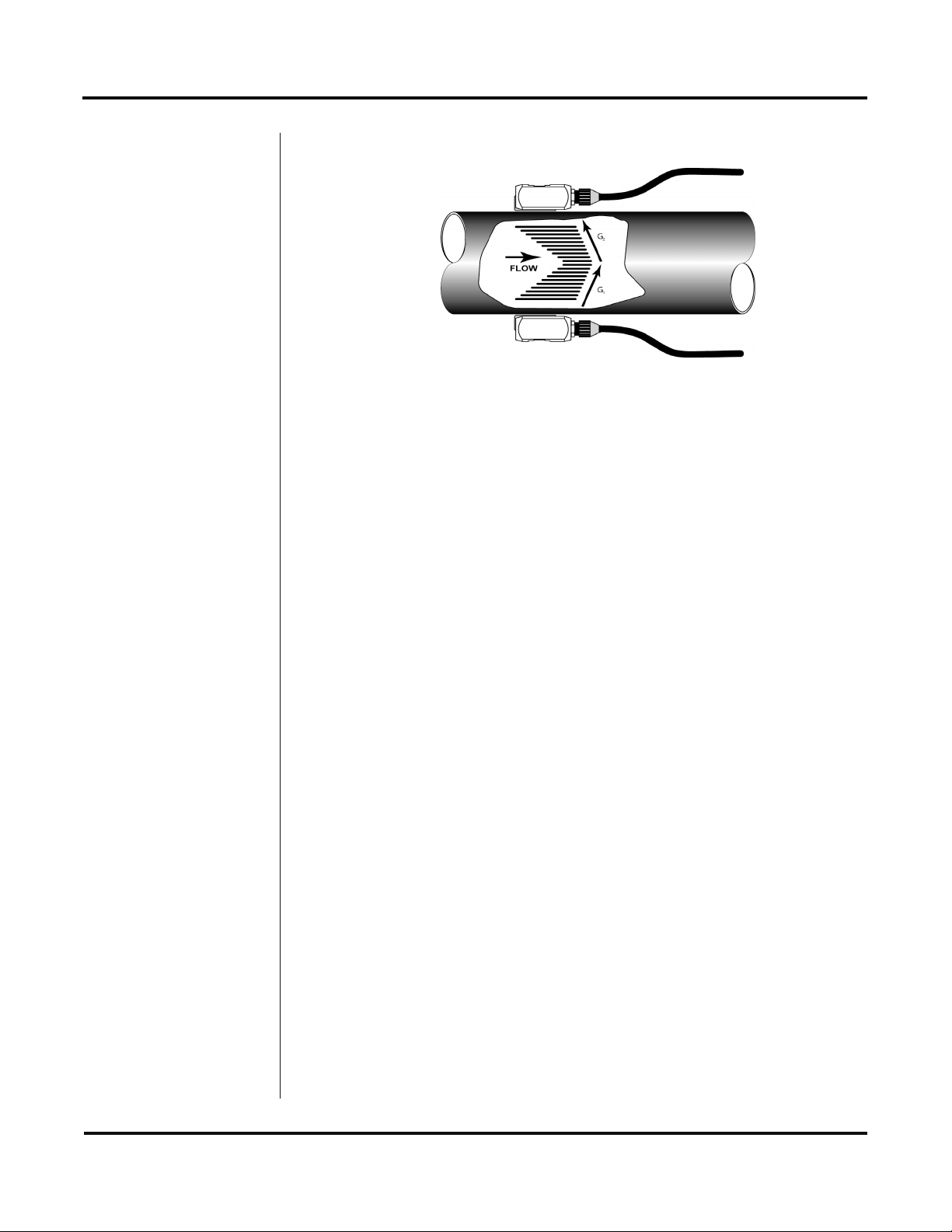
D. Place each transducer under the mounting strap, 180° apart on the
pipe. Ensure that the transducer cables are facing the same
direction on the downstream side of the flow. See Figure 1.2 on
page 1.2.
E. Route the transducer cable back to the FD-400 monitor, avoiding
conduits that contain high voltage AC supply wires.
Rev. 11/09 -1.1- Series FD-400
Page 4
QUICK-START OPERATING INSTRUCTIONS
Cables point in the
direction of flow
Top View of Pipe
Figure 1.2
Transducer Direction
Connections
Startup
3. TRANSDUCER CONNECTIONS
A. Mount FD-400 monitor within the length of the transducer cables.
While transducer cable extension is not generally recommended, if
additional transducer cable is required, utilize RG59 75 Ohm coaxial
cable and 75 Ohm interconnections such as BNC.
B. Route the transducer cables through the center conduit hole in the
bottom of the FD-400 enclosure and connect to terminal block J4.
The terminal blocks are a pluggable type and can be removed to
simplify wiring access. A wiring diagram is located on the inner
door for reference.
4. INITIAL SETTINGS AND POWER UP
A. Verify that the FD-400 power supply jumper settings are properly
configured for the power supply that will be utilized. A wiring and
jumper selection diagram is located on the inner door for reference.
NOTE: Power supply selection is specified during order placement
and appropriate jumpers are placed at the factory. If power is
changed from AC to DC or vice versa, the fuse requirement will
change. Fuse ratings are listed on the transmitter’s door.
B. Route power connections through the conduit hole farthest to the
left and in the FD-400 enclosure. Then connect power to the J2
terminal block. See Figure 3.2 on page 3.4.
C. Apply power.
D. On initial power-up, the FD-400 conducts a series of self-diagnostic
tests and buffering operations that take approximately 30 seconds.
E. Enter pipe internal diameter (Pipe ID), measuring units and output
configuration.
Rev. 11/09 -1.2- Series FD-400
Page 5

TABLE OF CONTENTS
Quick-Start Operating Instructions
Introduction
General
Applications
Product Specifications
Transducer Installation
Transducer Mounting Locations
Pipe Preparation
Page
1.1
1.5
1.5
1.7
2.1
2.3
Clamp-On Transducer Mounting
Probe Transducer Mounting
Transmitter Installation
Mounting Location
Dimensional Drawing
Transducer Wiring Connections
Power Supply Wiring Connections
Wiring Diagram
Multiple Meter Synchronization
ISO Modules—General Information
4-20 mA Module
2.3
2.6
3.1
3.2
3.3
3.3
3.4
3.7
3.8
3.9
Rev. 11/09 -1.3- Series FD-400
Page 6

TABLE OF CONTENTS
Control Relay Module
Rate Pulse Output Module
Instrument Programming
Keypad Operation
Totalizer Reset
Measurement Units Selection
Engineering Units Selection
4-20 mA Programming
Rate Pulse Programming
Dual Relay Configuration
Change Password
Advanced Set-up
Page
3.10
3.11
4.1
4.3
4.3
4.4
4.7
4.9
4.10
4.12
4.12
Startup and Troubleshooting
Startup Requirements
Troubleshooting
Appendix
FD-400 Software Map—General Operations
FD-400 Software Map—Output Configurations
Specific Gravity / Fluid Sound Speed Chart
Pipe Dimension Chart: ST, SS, PVC / Cast Iron / Ductile Iron
FPS to GPM Conversion Chart
5.1
5.2
Rev. 11/09 -1.4- Series FD-400
Page 7

PART 1 - INTRODUCTION
General
Application
Versatility
The FD-400 ultrasonic flow meter is designed to measure volumetric
flow of solids-bearing or aerated liquid within closed conduit. Transducers are available as non-contacting (FD-400C) or insertion probe
(FD-400I) types. FD-400C non-contacting transducers are strapped
to the outside of a pipe and are suitable for most installations where
the pipe material supports the transmission of ultrasound. Some
pipe materials, such as concrete pressure pipe and some plastic
lined pipes do not allow ultrasound to penetrate to the liquid inside.
For these applications, the FD-400I insertion probe will be needed.
The flow meter operates by transmitting an ultrasonic sound from its
transmitting transducer through the pipe wall or from the probe tip
into the moving liquid. The sound will be reflected by useful sonic
reflectors1 suspended within the liquid and recorded by the receiving
transducer. If the sonic reflectors are moving within the sound
transmission path, sound waves will be reflected at a frequency
shifted (Doppler frequency) from the transmitted frequency. The
shift in frequency will be directly related to the speed of the moving
particle or bubble. This shift in frequency is interpreted by the
instrument and converted to various user defined measuring units.
1
What makes a good Doppler reflector? The four criteria are:
The scattering material must have a sonic impedance (sound
speed difference) at least 10% different from the fluid.
There must be some particles large enough to cause longitudinal
reflection – particles larger than 35 micron.
For a given pipe size, the longitudinal reflection must have suffi-
cient energy to overcome the Rayleigh (energy wasting) scattering caused by smaller particles.
The reflecting material must travel at the same velocity as the
fluid for good accuracy.
The FD-400 flow meter can be successfully applied on a wide range
of metering applications. The easy to program transmitter allows
the standard product to be used on pipe sizes ranging from 1 - 120
inch (25 - 3050 mm) pipe I.D. With the small pipe transducer option,
the pipe size range is 0.25 - 1 inch (6 - 25 mm). A variety of liquid
applications can be accommodated: raw sewage, river water, plant
effluent, mining slurries, sludge, etc. Because the clamp-on
transducers are non-contacting and have no moving parts, the flow
meter is not affected by system pressure, fouling or wear. Standard
transducers are rated to 250 °F (121 °C). Optional high temperature
transducers are rated to operate to 400 °F (204 °C).
Rev. 11/09 -1.5- Series FD-400
Page 8

PART 1 - INTRODUCTION
User Safety
Data Storage
Product
Identification
The FD-400 employs modular construction and provides electrical
safety for the operator. The enclosure is constructed from rugged
polycarbonate plastic with UV inhibitors. The enclosure does not
contain any conductive materials that can become energized while
the door is closed. The keypad is also manufactured from
polycarbonate and is designed for outdoor use. The AC power
transformer provides 4,000 Volts of isolation from the power supply
mains. The display face contains voltages no greater than 24 Vdc.
Output modules are optically isolated from external power supplies
and provide a great degree of immunity to ground loops.
The FD-400 product retains all user configuration data and totalizer
accumulations in non-volatile FLASH memory indefinitely.
The serial number and complete model number of each FD-400 is
located on the inside of the monitor’s front cover. Should technical
assistance be required, please provide the Omega Customer
Service Department with this information.
Rev. 11/09 -1.6- Series FD-400
Page 9
PART 1 - INTRODUCTION
Rev. 11/09 -1.7- Series FD-400
Page 10
PART 2 - TRANSDUCER INSTALLATION
Unpacking
Mounting
Locations
After unpacking, it is recommended to save the shipping carton and
packing materials in case the instrument is stored or re-shipped.
Inspect the equipment and carton for damage. If there is evidence
of shipping damage, notify the carrier immediately.
The transducers that are utilized by the FD-400 contain piezoelectric
crystals for transmitting and receiving ultrasonic sound energy
through the pipe wall in the case of the Series FD-400C transducer
and from the probe tip of the Series FD-400I. Placement of the
ultrasonic transducer is the most critical step in achieving an accurate and reliable flow reading. All flow meters of this type rely on a
full-pipe of fluid that is flowing symmetrically (evenly) in the pipe.
Flow in partially filled pipes and immediately downstream of elbows,
valves and pumps is unstable and will lead to unstable readings and
non-linearity.
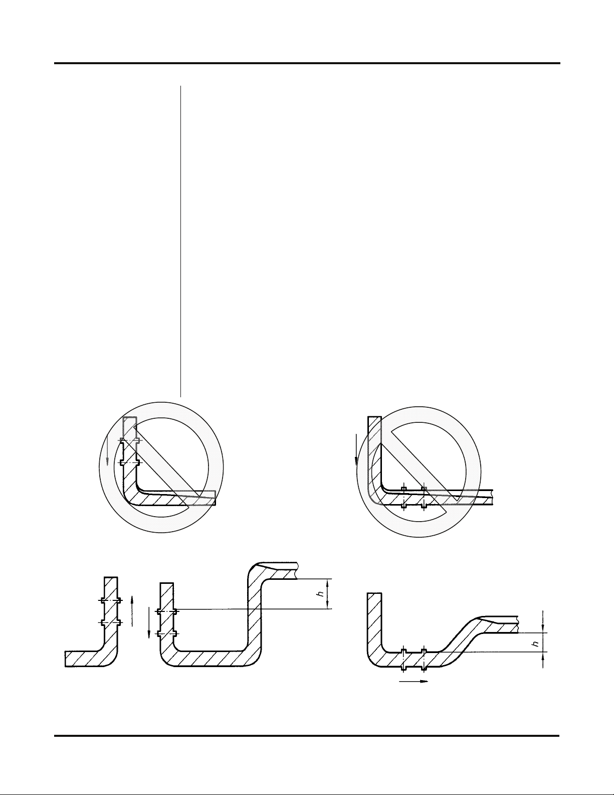
Figure 2.1 illustrates five possible pipe configurations and recommends installation only in locations where it can be guaranteed that
the pipe will be filled at all times when flow measurements are
required. The two locations illustrated in the top two drawings may
allow the meter to operate, but it is unlikely that stable and accurate
Figure 2.1
Pipe Configurations and Installation Recommendations
Rev. 11/09 -2.1- Series FD-400
Page 11
PART 2 - TRANSDUCER INSTALLATION
flow readings will be realized over a very large range of flow. Since
products like the FD-400 have software algorithms that assume a
full-pipe of liquid, partially-filled pipes can lead to very large flow
measurement errors and should be avoided.
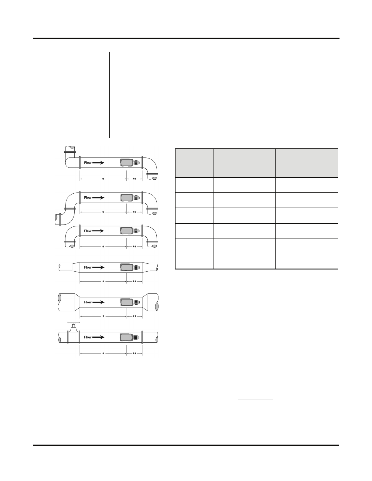
Select a transducer mounting location with adequate straight runs of
pipe, both upstream and downstream, to achieve stable readings1.
Examples of minimum upstream and downstream requirements are
included in Figure 2.2.
1
2
3
4
5
Example
1 24 5
2 14 5
3 10 5
4 10 5
5 10 5
6 24 5
* Upstream
Pipe Diameters
** Downstream
Pipe Diameters
6
Figure 2.2
Upstream/Downstream Pipe Requirements
1
The FD-400 system will provide repeatable measurements on
piping systems that do not meet these requirements, but the
accuracy
Rev. 11/09 -2.2- Series FD-400
may be influenced to various degrees.
Page 12

PART 2 - TRANSDUCER INSTALLATION
Pipe Preparation
Couplant
Before the transducer heads are mounted to the pipe surface, an
area slightly larger than the flat surface of the transducer face must
be prepared. If pipe insulation is present, it must be peeled back to
expose the pipe surface. Typical preparation involves wire brush
removal of loose paint, rust, scale or dirt. Paint, if bonded well to
the pipe surface, does not need to be removed. The bumps present
on ductile iron pipe do not need to be removed. Thoroughly dry the
mounting surfaces so that the couplant grease will properly bond to
the surface.
NOTE: Small pits in the piping surface typically do not significantly
impact ultrasonic transmission or signal reception.
To assure an acoustically conductive path between the transducer
face and the prepared piping surface, a coupling compound is
employed. Clamp-on ultrasonic meters will not operate without
coupling compound mounted between the pipe wall and the transducer face. Enclosed with the FD-400 system is a tube of coupling
compound that is adequate for general purpose applications.
Omega prefers silicone-based valve grease or RTV (Room Temperature Vulcanizing) products or grease for Doppler installations as
they operate over a very wide temperature range. In some installations, such as automotive, silicone is not permitted. Alternate petroleum-based products can be utilized, but verify that the grease is
rated not to flow at the maximum surface temperature anticipated on
the pipe.
In general, utilize the following couplants with these transducers:
FD-400C Dow 732 or Dow 111 (or equivalent)
FD-400C-HT Dow 112 or Pyrogel Grade 100
FD-400I Not applicable
FD-400C
Clamp-On
Transducer
Mounting
Rev. 11/09 -2.3- Series FD-400
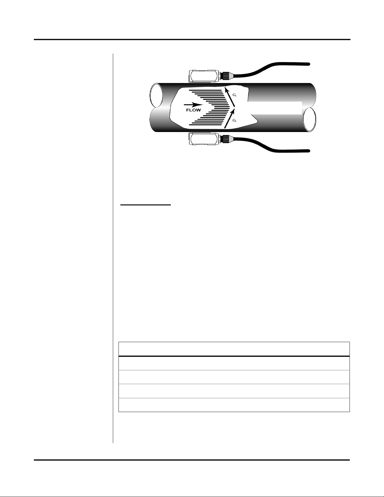
Clamp-on transducers should be mounted on the pipe 180° apart
and facing each other on the pipe, with the cables on the downstream side of the transducers. If the pipe is horizontal, the
preferred mounting orientation is 3 and 9 o’clock, with 12 o’clock
being the top of the pipe. See Figure 2.3 on page 2.4. Orientation
on vertical pipes does not matter. FD-400I insertion probe transducer installation starts on page 2.6.
Page 13
PART 2 - TRANSDUCER INSTALLATION
Top View of Pipe
Figure 2.3
Transducer Placement
PROCEDURE:
1. Large pipe installations utilize stainless steel straps to secure the
transducers to the outside of the pipe. The FD-400 system is
shipped with four 36 inch (900 mm) straps, which are suitable for
pipes up to 39 inches (1000 mm) diameter. Select the proper
number of transducer straps to allow a complete strap to go
around the circumference of the pipe. If a pipe is larger than 39
inches (1000 mm), it is recommended that a single strap/buckle
arrangement be utilized to reduce the number of strap connections. See Figure 2.4. The straps can be connected together to
make a continuous length. Small pipe installations do not utilize
straps, but use an integral clamping mechanism built into the
transducer.
2. Wrap the strap around the pipe in the area where the
Pipe Sizes Straps Required
1" to 9" 25 to 225 mm 1
10" to 19" 250 to 480 mm 2
20" to 29" 500 to 740 mm 3
30" to 39" 760 to 1000 mm 4
Figure 2.4
Straps Required vs. Pipe Size
Rev. 11/09 -2.4- Series FD-400
Page 14

PART 2 - TRANSDUCER INSTALLATION
transducers are to be mounted. Leave the strap loose enough to
allow the transducers to be placed underneath. If multiple straps
are being used, it can be beneficial to wrap electrical tape
around all but one
screws in place.
3. Spread an even layer of coupling compound, approximately
⅛ inch (3mm) thick, to the prepared transducer mounting areas
of the pipe.
4. Spread an even layer of coupling compound, approximately
⅛ inch (3mm) thick, to the flat face of the two transducers.
5. Place each transducer under the strap with the flat face – amber
plastic window – positioned towards the pipe. The notch on the
back of the transducer will provide a mounting surface for the
strap. The transducer cables must be facing in the same
direction and downstream of the transducers for proper
operation.
strap connection to secure the strap worm
NOTE: Large pipes may require two people for this procedure.
6. Tighten the strap strong enough to hold the transducers in place,
but not so tight that all of the couplant squeezes out of the gap
between the transducer face and pipe. Ensure that the
transducers are squarely aligned on the pipe and 180° apart. If
RTV is utilized, avoid moving the transducers during the curing
time – typically 24 hours – as bubbles may form between the
transducer and pipe that can reduce ultrasonic signal transmission to unsatisfactory levels.
7. Route the transducer cables back to the area where the
transmitter will be mounted, avoiding high voltage cable trays
and conduits. While transducer cable extension is not generally
recommended, if additional transducer cable is required, utilize
RG59 75 Ohm coaxial cable and 75 Ohm interconnections such
as BNC terminations. Failure to use proper cables can lead to
improper operation of the FD-400 flow meter. Excess cable may
be coiled to take up extra length or cutoff.
8. If the transducers are to be permanently mounted using Dow
732, the RTV must be completely cured before proceeding to
Instrument Start-up. Ensure that no relative motion between the
transducer and pipe occurs during the 24 hour curing process. If
Dow 111 grease was used for temporary operation of the FD400 system, proceed with the Instrument Start-up procedures.
Rev. 11/09 -2.5- Series FD-400
Page 15
PART 2 - TRANSDUCER INSTALLATION
A
FD-400I Probe
Transducer
Mounting
The FD-400I insertion transducer that is utilized by the FD-400
contains piezoelectric crystals for transmitting and receiving
ultrasonic sound energy. The black Ultem® plastic tip of the FD-400I
contains these crystals, which are designed to be inserted just into
the path of the flowing liquid.
Select a transducer mounting location that will be completely filled
with liquid when flow measurements are to be made – See Figure
2.1 on page 2.1 – and with adequate straight runs (without
disturbances) of pipe, both upstream and downstream, to achieve
stable and accurate readings. Examples of minimum upstream and
downstream requirements are included in Figure 2.2 on page 2.2.
Note that if adequate straight piping cannot be provided, the FD400 system will operate repeatably, but will probably not achieve
ideal accuracy.
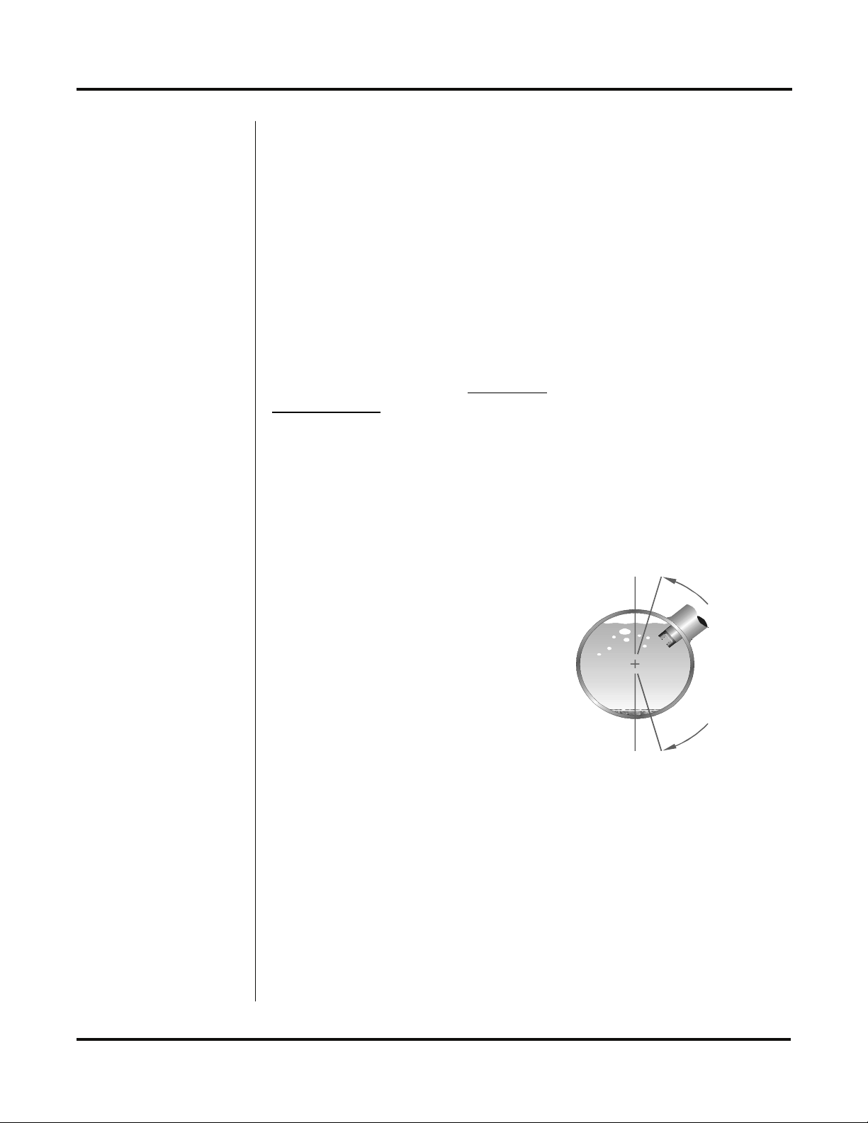
When installing the FD-400I transducer in a horizontal pipe, the
preferred orientation is at least 20 degrees from the top or bottom of
the pipe – See Figure 2.5. Ensure that the mounting location allows
for adequate clearance to install and retract the probe fully from the
pipe.
TOP V IEW
OF PIPE
20°
I
N
S
T
A
L
L
Figure 2.5
Acceptable
Installation Locations
20°
Install Doppler Probe between 1 o’clock
INSTALL MAGPROBE
BETWEEN 1 O’CLOC K
and 5 o’clock on the pipe
ND 5 O’CLOCK ON THE PIPE
A
T
I
O
N
R
A
N
G
E
The instructions cover hot tapped installations (installations where
it is required to install or remove the transducer probe without
shutting down the process pressure). If the product is being
installed without an isolation valve, ignore the steps that pertain to
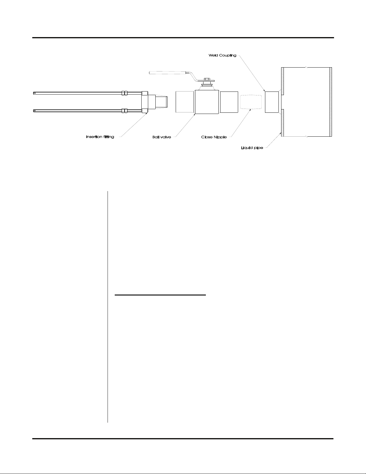
its installation. Figure 2.6 on page 2.7 illustrates an exploded view
of an isolation valve assembly and names the various components.
Rev. 11/09 -2.6- Series FD-400
Page 16
PART 2 - TRANSDUCER INSTALLATION
Figure 2.6
Hot Tap Installation
If FD-400I-BV or FD-400-SSV accessory kits were ordered with the
FD-400I probe, a hot tapped installation can be completed. The kits
include an isolation valve assembly and are designed for installation
in pipes under pressure, up to 700 psi (48 bar) at 70 F (21º C).
All items required for installation are provided with the kit, except for
the 1-½" NPT weld coupling or service saddle and the drilling and
welding equipment. These instructions call for the use of a drilling
machine designed for operations under pressure (for example,
Muller Co., Decatur, Illinois).
Procedures are as follows:
1. Verify that the pipe’s line pressure is within the rated limits of
the pressure drilling machine to be used.
2. Grind off paint or other coatings from the pipe in the area where
the FD-400I Probe Assembly is to be installed.
3. Tack weld a 1-½" NPT weld coupling to the pipe or install a
service saddle according to the supplier’s instructions. The
coupling or saddle must be aligned perpendicular to the pipe
axis and square to its plane.
Rev. 11/09 -2.7- Series FD-400
Page 17

PART 2 - TRANSDUCER INSTALLATION
4. Complete welding. A water tight, 0.25" minimum weld bead is
recommended.
5. Install the close nipple (supplied with assembly) into the weld
coupling. Use appropriate pipe sealants.
6. Install the isolating ball valve on the close nipple. Verify that the
valve is in fully open position.
7. Install drill bit and adapter into the pressure drilling machine.
Then attach the machine to the isolation valve.
8. Drill through the pipe wall in accordance with the instructions
supplied with the drilling machine.
9. Withdraw the drill bit through the isolating valve. Close the
valve and remove the drilling machine. Check for leakage at
valve and connections.
10. Place pipe sealant on the 1-½" NPT threads of the insertion
fitting assembly. Screw the assembly into the isolation valve
and tighten with a 2-½" pump wrench.
PROBE INSERTION
Before inserting the FD-400I probe into the piping system, it is
necessary to calculate the probe insertion depth that will place the
measuring electrodes at the proper position in the pipe. In order to
complete this calculation, some knowledge of the piping system
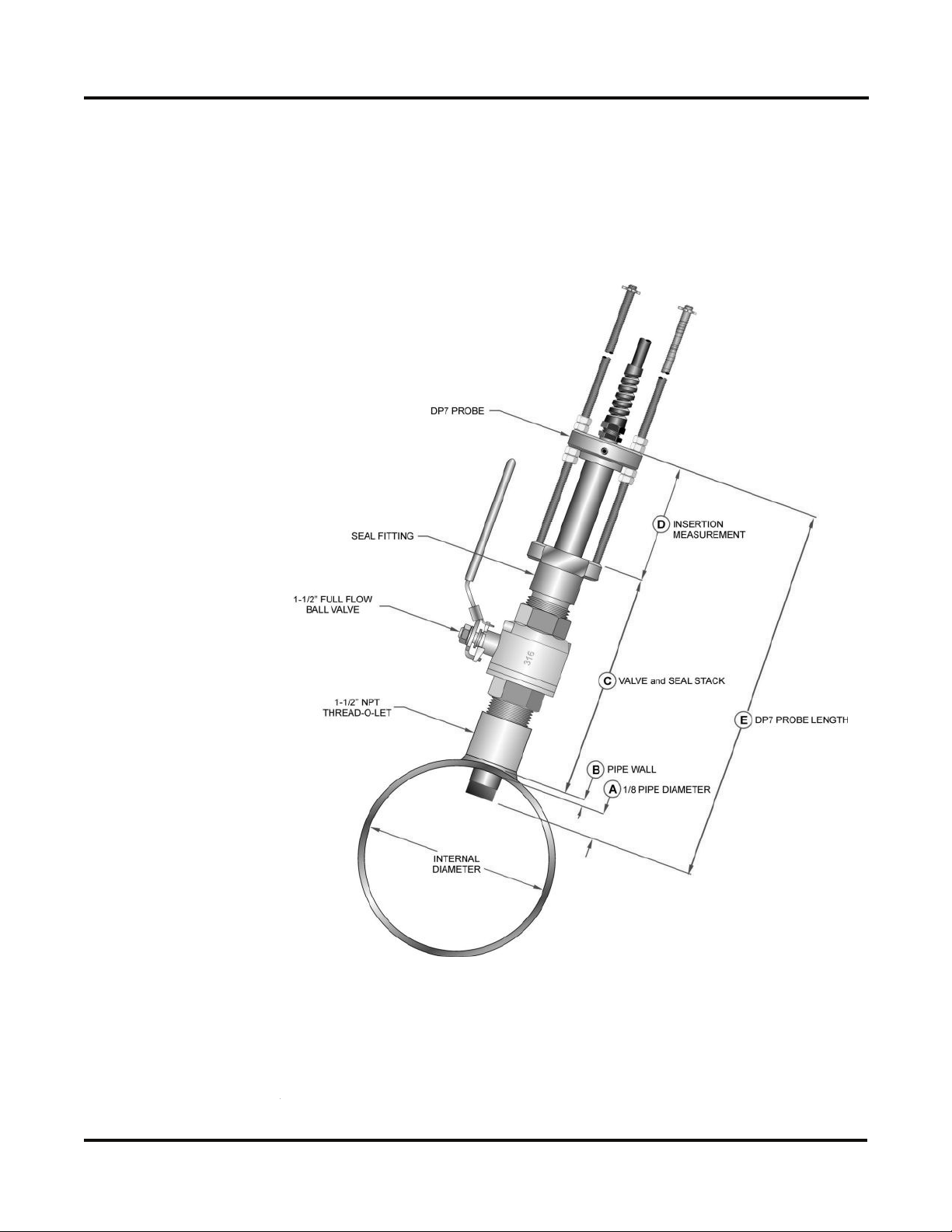
must be known. Refer to the paragraphs that follow and Figure 2.7
on page 2.10 for information regarding this process. The variables
required are:
The overall probe length
Pipe internal diameter (I.D.)
Pipe wall thickness
The length of the valve stack
Amount of straight pipe diameters in the system
Using this information and referring to Figure 2.7, proper insertion
depth can be determined.
Rev. 11/09 -2.8- Series FD-400
Page 18

PART 2 - TRANSDUCER INSTALLATION
Measurement A — The typical depth that the FD-400I probe tip is
inserted into the piping system is ⅛ (12.5%) of the pipe internal
diameter.
Measurement B — Pipe wall thickness. This information can be
obtained from standard pipe wall charts (See the Appendix of this
manual) or ideally can be measured using an ultrasonic wall thickness gauge.
Measurement C — Measure the distance that is going to be taken
up by the pipe tap, nipple, full-flow ball valve and the insertion fitting.
FD-400I probes utilize 1-½" NPT hardware and the insertion fitting is
approximately 2.5 inches in height.
Measurement E — This is the overall length of the probe measured
from the black measurement tip to the top flange on the probe.
Measurement D — This is the length of FD-400I probe that will be
protruding from the insertion fitting after it is inserted to the proper
depth in the fluid stream.
1. Lubricate the O-rings located within the FD-400I probe seal
fitting so that the seals are not damaged during probe insertion.
2. Run the lower jam nuts down to a point that approximates the
final insertion position or at least far enough to allow insertion
into the insertion fitting. Using the threaded rods as a guide,
position the probe in the insertion fitting. Continue to insert the
probe as far into the isolation assembly as possible. The probe
tip will come in contact with the closed “ball” in the isolation
valve.
CAUTION: Do Not Force the Probe Tip Against the “Ball”, as
damage to the probe tip may result.
3. Replace the upper jam nuts (2 on each rod) and the cotter pins.
The nuts should be run down to the top side of the retaining
collar and the cotter pins replaced. Orient the probe in the
direction of flow as indicated by the FLOW direction arrow
located on the top of the probe flange. See Figure 2.8 on page
2.12. Lock the probe in position with the enclosed allen wrench.
CAUTION: The nuts on both ends of the retaining rods must
always be in place as a safety measure to prevent possible probe
blow out. Inserting cotter pins is a further safety measure.
Rev. 11/09 -2.9- Series FD-400
Page 19
PART 2 - TRANSDUCER INSTALLATION
TO CALCULATE INSERTION DEPTH
Measure and record the following linear distances:
E = PROBE LENGTH = _______
C = SEAL FITTING TO PIPE WALL
= _______
B = PIPE WALL THICKNESS
= _______
A = 0.125 × PIPE ID = _______
D = INSERTION DEPTH = _______
D = E - C - B - A
Figure 2.7
Installation Measurements
Rev. 11/09 -2.10- Series FD-400
Page 20

PART 2 - TRANSDUCER INSTALLATION
4. Slowly open the isolation valve. When the valve is fully open,
use the proper size wrench on the insertion nuts, alternately
tightening each nut about two complete turns to avoid uneven
seal loading.
NOTE: For some low pressure/low temperature applications [less
than 30 PSI (2.1 Bar) and less than 100 oF (38 oC)], the probe may
be pushed in by hand to decrease the insertion time.
PROBE CABLES
Before inserting the probe into the pipe, the sensor cables should be
routed to the transmitter location. Verify that the supplied cable
length is sufficient to meet the installation requirements. While
transducer cable extension is not generally recommended, if additional transducer cable is required, utilize RG59 75 Ohm coaxial
cable and 75 Ohm interconnections such as BNC terminations.
CAUTION: The probe cables are designed to carry low level
signals that are developed by the sensor. Care should be taken in
routing the cables. Avoid running cables near sources of high
voltage or EMI/RFI. Also avoid routing the cables in cable tray
configurations, unless the trays are specifically used for other low
voltage, low level signal cables.
CAUTION: The internal FD-400I probe wiring is epoxy
encapsulated to seal it from moisture. The FD-400I probe is
provided with two coaxial cables to shield the low level signals and
must be continuous to the FD-400I probe transmitter. Excess wire
may be cutoff or simply coiled near the FD-400 instrument.
PROBE RETRACTION PROCEDURE
1. Retract the probe by loosening the upper jam nuts
counterclockwise as viewed from the top of the probe using the
proper size wrench. If the pipe is under pressure, the nuts must
be turned alternately about two turns at a time to prevent binding
as a result of non-equal seal loading. In many cases, the line
pressure will cause the probe to retract. Should the probe bind,
use the retraction nuts on the lower side of the probe flange to
assist in the probe retraction. Continue this procedure until the
probe is fully retracted into the isolation valve.
Rev. 11/09 -2.11- Series FD-400
Page 21

PART 2 - TRANSDUCER INSTALLATION
Figure 2.8
Flow Direction
Arrow
CAUTION: Do not run the drive nuts off the rods until the isolation
valve is fully closed.
2. After the probe is retracted past the “ball” in the isolation valve,
the isolation valve may be closed to isolate the probe from the
line and the probe can be removed entirely.
CAUTION: If the insertion probe is not above the “ball” of the
isolation valve, the valve cannot be closed. If the valve will not
close smoothly, the body or tip of the probe is most likely not above
the “ball”. Attempting to force the valve into the closed position may
result in damage to the probe.
Rev. 11/09 -2.12- Series FD-400
Page 22

Mounting
Location
PART 3 - TRANSMITTER INSTALLATION
After unpacking, it is recommended to save the shipping carton and
packing materials in case the instrument is stored or re-shipped.
Inspect the equipment and carton for damage. If there is evidence
of shipping damage, notify the carrier immediately.
The enclosure should be mounted in an area that is convenient for
servicing, calibration and for observation of the LCD readout.
1. Locate the transmitter within the length of transducer cable that
was supplied with the FD-400 system. If this is not possible, it is
recommended that the cable be exchanged for one that is of
proper length. While transducer cable extension is not generally
recommended, if additional transducer cable is required, utililize
RG59 75 Ohm coaxial cable and 75 Ohm interconnections such
as BNC terminations. Transducer cables that are up to 990 feet
(300 meters) may be accommodated.
2. Mount the FD-400 transmitter in a location that is:
Where little vibration exists
Protected from falling corrosive fluids
Within ambient temperature limits -40 to +185°F (-40 to +85°C)
Out of direct sunlight. Direct sunlight may increase transmitter
temperature to above the maximum limit
3. Mounting: Refer to Figure 3.1 on page 3.2 for enclosure and
mounting dimension details. Ensure that enough room is
available to allow for door swing, maintenance and conduit
entrances. Secure the enclosure to a flat surface with four
appropriate fasteners.
4. Conduit holes: Conduit hubs should be used where cables enter
the enclosure. Holes not used for cable entry should be sealed
with plugs.
NOTE: Use NEMA 4 (IP-65) rated fittings/plugs to maintain the
watertight integrity of the enclosure. Generally, the left conduit hole
(viewed from front) is used for line power, the center conduit hole for
transducer connections and the right hole is utilized for ISO-MOD
I/O wiring.
5. If additional holes are required, drill the appropriate size hole in
the enclosure’s bottom. Use extreme care not to run the drill bit
into the wiring or circuit cards.
Rev. 11/09 -3.1- Series FD-400
Page 23

PART 3 - TRANSMITTER INSTALLATION
Figure 3.1
FD-400 Transmitter Installation Dimensions
Rev. 11/09 -3.2- Series FD-400
Page 24

PART 3 - TRANSMITTER INSTALLATION
Transducer
Wiring
Connections
Power Supply
Wiring
Connections
To access terminal strips for electronic connectors, loosen the two
screws in the enclosure door and open the door.
1. Guide the transducer terminations through the transmitter
conduit hole located in the bottom-center of the enclosure.
Secure the transducer cable with the supplied conduit nut (if
flexible conduit was ordered with the transducer).
2. The terminals within the FD-400 are a pluggable type – they can
be removed, wired and then plugged back in. Connect the
appropriate wires to J4 at the corresponding screw terminals in
the transmitter. See Figure 3.2 on page 3.4 or the Wiring
Diagram located on the inner door of the transmitter.
NOTE: The transducer cable carries low level high frequency
signals. While transducer cable extension is not generally recommended, if additional transducer cable is required, utilize RG59 75
Ohm coaxial cable and 75 Ohm interconnections such as BNC
terminations. Cables to 990 feet (300 meters) are available.
Connect power to the screw terminal block marked J2 in the FD-400
transmitter. See Figure 3.3 on page 3.5 for AC power supplies and
Figure 3.4 on page 3.6 for DC power supplies. Utilize the conduit
hole on the left side of the enclosure for this purpose. Use wiring
practices that conform to local and national codes (e.g., The
National Electric Code Handbook in the U.S.).
CAUTION: Any other wiring method may be unsafe or cause
improper operation of the instrument.
NOTE: This instrument requires clean electrical line power. Do not
operate this unit on circuits with noisy components (i.e., fluorescent
lights, relays, compressors or variable frequency drives). It is
recommended not to run line power with other signal wires within
the same wiring tray or conduit.
Rev. 11/09 -3.3- Series FD-400
Page 25

PART 3 - TRANSMITTER INSTALLATION
WIRING DIAGRAM
CAUTION! To avoid serious injury or product damage,
!
disconnect electrical power before servicing this meter.
JP 3
Conn ectio ns
241
11 5 V A C
3
2
1
230 VA C
4
3
241
9-28 VDC
3
JP 1/J P2
Conn ectio ns
115/230
VAC
9-28 VDC
221
2
2
1
1
Fuse (5x20mm)
AC: 0.1A/250V Delay
DC: 0.5A/250V Delay
1
AC L1 L2 EARTH
DC +V GND EA RTH
JP3
4
JP1
J3
132
MODULE #2
1
2
JP2
2
1
J4
J2
MODULE #1
RED BLK BLK RED
Receive Transmit
EXT SYNC
GND
INT
EXT
SYNC SELECT
Figure 3.2
FD-400 Wiring Diagram
Rev. 11/09 -3.4- Series FD-400
Page 26

PART 3 - TRANSMITTER INSTALLATION
AC Power
Supply
NOTE: Jumpers
positioned for
115 VAC operation.
230 VAC operation
requires an
alternate position.
AC POWER CONNECTIONS
1. Verify that the jumpers at JP3 are properly oriented for the power
supply. See Figure 3.2 on page 3.4. Verify that the jumpers at
JP1 and JP2 are not present.
2. Connect L1, L2 and EARTH to the terminals referenced in
Figure 3.2. Phase and neutral connections to L1 and L2 are not
polarized. Do not operate without an earth ground connection.
3. See Figure 3.3 for AC connection schematic. Wire gauges up to
14 AWG can be accommodated in the FD-400 terminal blocks.
50/60 Hz
@ 5 W Max
Figure 3.3
AC Power Connection
Rev. 11/09 -3.5- Series FD-400
Page 27

PART 3 - TRANSMITTER INSTALLATION
DC Power
Supply
DC POWER CONNECTIONS
The FD-400 may be operated from a 12-28 VDC source, as long as
the source is capable of supplying a minimum of 2.5 Watts.
12 VDC Supply @ 208 mA minimum
24 VDC Supply @ 104 mA minimum
1. Verify that the jumpers are properly placed. See the Wiring
Diagram located on the inside door of the FD-400 enclosure or
see Figure 3.2 on page 3.4. The jumpers at JP3 should not be
present and the jumpers at JP1 and JP2 will be in place.
2. Connect the DC power source as illustrated in the schematic in
Figure 3.4. Wire up to 14 AWG can be accommodated in the
FD-400 terminal blocks.
+ -
12-28 VDC @ 2.5 W
Figure 3.4
DC Power Connection
Rev. 11/09 -3.6- Series FD-400
Page 28

PART 3 - TRANSMITTER INSTALLATION
Multiple Meter
Synchronization
Multiple Meter Installations
The FD-400 flow meter contains a provision for synchronizing
multiple FD-400 flow meters together. Synchronization is required
when more than one FD-400 flow meter is mounted on a common
pipe or header system. If meters are not synchronized, a phenomena called “cross-talk” can occur between meters, which can lead to
erroneous readings and inoperability. Cross-talk results from the
small differences in transmitted frequency generated from two or
more different ultrasonic flow meters. By synchronizing the transmitted ultrasonic energy, cross-talk caused by differences in transmitted
frequency is eliminated.
The FD-400 synchronization circuit is designed to interconnect up to
four FD-400 flow meters over a cable length of 100 feet (30 meters).
Utilize 20-22 AWG twisted-pair shielded interconnection wire for this
purpose. See Figure 3.5.
To synchronize multiple meters:
1. Remove power from the FD-400 flow meters.
2. Daisy-chain connect the EXT SYNC and GND terminal blocks
together between the meters to be synchronized, utilizing the
twisted-pair cable described previously. The terminal block is
located on the circuit board that is mounted on the door of the FD
-400 monitor. See Wiring Diagram on page 3.4, the decal on the
inner door of the FD-400 monitor or schematic below.
3. At a single point, connect the shield drain wire from the interconnection cable to earth ground.
4. Configure the SYNC SELECT jumpers on the FD-400 flow
meters. One FD-400 should be configured for INT and the
remaining units configured for EXT (see below).
5. Apply power to the FD-400 system.
Figure 3.5
FD-400 Synchronization Connections
Rev. 11/09 -3.7- Series FD-400
Page 29

PART 3 - TRANSMITTER INSTALLATION
ISO Modules
The FD-400 utilizes ISO-MODs for input and output functions. ISOMODs are epoxy encapsulated electronic input/output modules that
are simple to install and replace in the field. See Figure 3.6. All
modules are 2,500 V optically isolated from FD-400 power and earth
grounds. This eliminates the potential for ground loops and reduces
the chance of severe damage in the event of an electrical surge.
Three ISO-MOD options are available, including: 4-20 mA, dualrelay and rate pulse. The FD-400 supports any two ISO-MOD input/
output modules. All modules are field configurable by utilizing the
keyboard interface. Field wiring connections to ISO-MODs are
quick and easy using pluggable terminals. Configuration and
connection of the various ISO-MODs are described on the following
pages.
Figure 3.6
Two ISO-MOD I/O Modules Installed
ISO-MOD
Replacement
Rev. 11/09 -3.8- Series FD-400
To remove an ISO-MOD, remove the two machine screws that
secure the module in place and pull the module straight out of the
enclosure. A 10-pin connection is on the bottom of the module that
mates with the circuit board underneath. Installation of a module is
simply the reverse operation of removal. 4-20 mA modules will
require calibration parameters to be entered if the module is replaced. See Part 4 of this manual for instructions on entry of
calibration parameters.
Page 30

PART 3 - TRANSMITTER INSTALLATION
4-20 mA Output
Module
The 4-20 mA Output Module interfaces with most recording and
logging systems by transmitting an analog current signal that is
proportional to system flow rate. The 4-20 mA ISO-MOD may be
configured via jumper selections for either an internally powered
(Figure 3.7A) or externally powered (Figure 3.7B) mode.
Internal Power Configuration: Ensure that jumpers are in place at
JP1 and JP2 on the module – reference Figure 3.7A. In this
configuration, the 4-20 mA output is driven from a +24 VDC source
located within the FD-400 flow meter. The 24 VDC source is
isolated from DC ground and earth ground connections within the
FD-400 instrument. The module can accommodate loop loads up to
800 Ohms in this configuration.
NOTE: The +24 internal supply, if configured to power the 4-20 mA
output, shares a common ground with another ISO-MOD (if
installed). If another module is connected to earth ground, a ground
loop may occur. The solution to this problem is to configure the 420 mA module for external power and utilize an external isolated
supply to power the 4-20 mA loop.
External Power Configuration: Remove the two jumpers located at
JP1 and JP2 on the module – reference Figure 3.7B. In this
configuration the 4-20 mA module requires power from an external
DC power supply. The voltage of the external power source must
be sufficient to power the module and drive the loop load. The loop
loss attributed to the ISO-MOD is 7 VDC, so the minimum voltage
required to power a loop can be calculated using the following formula:
Loop voltage (min) = (loop load Ohms × 0.02) + 7
Figure 3.7A
Internally Powered
4-20mA
Figure 3.7B
Externally Powered
4-20mA
Rev. 11/09 -3.9- Series FD-400
Page 31

PART 3 - TRANSMITTER INSTALLATION
Control Relay
Output Module
Two independent SPDT (single-pole, double-throw, Form C) relays
are contained in this module. The relay operations are user
configured via the front panel to act in either a flow rate alarm, error
alarm or totalizing pulse. The relays are rated for 200 VAC
maximum and have a current rating of 0.5 A resistive load (175 VDC
@ 0.25 A resistive). It is highly recommended that a secondary relay
be utilized whenever the Control Relay ISO-MOD is used to control
inductive loads such as solenoids and motors.
Typical relay connections are illustrated in Figure 3.8A. The reed
relays located within the relay module can interface directly with
small pilot lights, PLCs, electronic counters and SCADA systems.
Figure 3.8B describes the connection of an external power relay to
the Relay ISO-MOD. It is recommended that external power relays
are utilized whenever the load to be switched exceeds the switch
rating of the reed relays, or if the load is inductive in nature.
Figure 3.8A
Typical Relay
Connections
Figure 3.8B
External Relay
Connections
Rev. 11/09 -3.10- Series FD-400
Page 32

PART 3 - TRANSMITTER INSTALLATION
Rate Pulse
Output Module
The Rate Pulse Output Module is utilized to transmit information to
external counters and PID systems via a frequency output that is
proportional to system flow rate. The frequency output range of the
Rate Pulse Module is 0-2,500 Hz. This module has two types of
outputs: one simulates the output of the coil of a turbine flow meter
and the other is an open-collector type that does not source voltage
at its output. Both outputs may be connected simultaneously.
The turbine meter output creates a 500 mV peak-to-peak saw-tooth
waveform that is not referenced to ground. This output can be run
to electronic monitors that are compatible with variable reluctance
outputs from coils, such as those found in turbine and paddle-wheel
flow meters. The input impedance of the receiving device should
not be smaller than 2,000 Ohms.
The standard pulse output does not output a voltage, but acts as an
“open-collector” output requiring an external power source and pullup resistor. See Figure 3.9. The MOSFET in the Rate Pulse
Module can support loads of 100 V @ 1 A. Resistor selection is
based on the input impedance of the receiving device. Select a
resistor that is a maximum of 10% of the input impedance of the
receiving device, but does not exceed 10k Ohms.
Figure 3.9
Rate Pulse Module
Rev. 11/09 -3.11- Series FD-400
Page 33

PART 4 - INSTRUMENT PROGRAMMING
General
Keypad
Operation
The FD-400 is configured through the keypad interface. All entries
are saved in non-volatile FLASH memory and will be retained
indefinitely in the event of power loss.
The FD-400 contains a four-key tactile feedback keypad interface
that allows the user to view and change configuration parameters
used by the FD-400 operating system.
V
V
Figure 4.1
Keypad Layout
The FD-400 allows two basic sets of programming procedures: list
item selection and numeric value entry.
NOTE: While in RUN mode, pressing both the UP and DOWN
arrow keys will display the current firmware version installed in the
meter.
List Item Selection Procedure
NOTE: If you are already in PROGRAM mode and the selection to
be viewed or changed is already displayed, proceed to step 3
below. If you are in PROGRAM mode and the selection to be
viewed or changed is not displayed, press the UP or DOWN arrow
keys and repeat pressing until the desired selection appears.
Proceed to step 3.
1. Press MENU. PROGRAM appears in the lower left-hand corner
and ID UNITS appears on the lower line of the display.
2. Press the DOWN arrow key to move to the desired selection.
3. Press ENTER to view the current selection.
4. If the current selection is desired, press ENTER to confirm. The
unit will automatically advance to the next selection.
5. If the current selection must change, press the UP arrow key and
repeat pressing to scroll through the available choices. Press
ENTER to confirm your selection. The unit will automatically
advance to the next selection.
Rev. 11/09 -4.1- Series FD-400
Page 34

PART 4 - INSTRUMENT PROGRAMMING
6. To exit programming mode, press the MENU key. Depending on
your position in the programming mode, up to three MENU key
presses may be required to exit. The display will change to RUN
mode.
NOTE: The FD-400 firmware revision can be displayed by pressing
both arrow keys simultaneously.
Numeric Value Entry Procedure
NOTE: If you are already in PROGRAM mode and the selection to
be viewed or changed is already displayed, proceed to step 3
below. If you are in PROGRAM mode and the selection to be
viewed or changed is not displayed, press the UP or DOWN arrow
keys and repeat pressing until the desired selection appears.
Proceed to step 3.
1. Press MENU. PROGRAM appears in the lower left-hand corner
and ID UNITS appears on the lower line of the display.
2. Press the DOWN arrow key until the desired selection displays.
The current numeric value for this selection appears on the
upper line of the display.
3. If the current value is desired, press ENTER. The left most
programmable number begins to flash. Press ENTER again to
confirm and keep the current numeric value. The unit will
automatically advance to the next menu selection.
4. If the current selection must be changed, press ENTER. The left
most programmable number begins to flash. Use the UP arrow
key to scroll through the digits 0-9 and change the flashing digit
to the desired value. Use the DOWN arrow key to move the
active digit to the right. Continue using the UP and DOWN arrow
keys until all digits are selected.
5. Press ENTER to confirm your selection. The unit will automatically
advance to the next selection.
6. To exit programming mode, press the MENU key. Depending on
your position in the programming mode, up to three MENU key
presses may be required to exit. The display will change to RUN
mode.
Rev. 11/09 -4.2- Series FD-400
Page 35

PART 4 - INSTRUMENT PROGRAMMING
Menu
Structure
Totalizer
Reset
Measurement
UNITS
Selection
The FD-400 software is structured using menus. A menu map of
the user interface is included in the Appendix of this manual. The
map provides a visual path to the configuration parameters that
users can access. This tool should be employed each time
configuration parameters are accessed or revised.
Press both the ENTER and the MENU keys when in the RUN mode
to reset the totalizer. The message TOTAL RST will be displayed
for a few seconds to indicate that the totalizer had been cleared. If
a password has been set, the user must enter the correct password
for the totalizer to be cleared.
The following sections define the configuration parameters
accessible in the program mode.
ID UNITS
INCH
MM
Selects unit of measure for pipe ID entry. The choices are either
inches (English) or millimeters (Metric) units.
Pipe Inside
Diameter
Flow Display
Mode
PIPE ID – Pipe Inside Diameter Entry
ENGLSH (Inches)
METRIC (Millimeters)
Enter the pipe inside diameter in inches if INCH was selected as ID
UNITS; in millimeters if MM was selected.
DISPLAY – Display Mode Selection
RATE
TOTAL
BOTH
DIAG
Rev. 11/09 -4.3- Series FD-400
Page 36

Engineering
Units
RATE
PART 4 - INSTRUMENT PROGRAMMING
To display only the Flow Rate, select RATE. To display only the
Flow Total, select TOTAL. To alternately display the Flow Rate and
the Total, select BOTH. By selecting BOTH, the display will switch
between RATE and TOTAL every 7 seconds.
The DIAG selection places the display in the diagnostics mode.
When selected, the display will show the measured frequency, the
gain setting and the signal strength.
RATE UNT – Engineering Units for Flow Rate
VEL FEET - Velocity in Linear Feet
VEL MTRS - Velocity in Linear Meters
GALLONS - U.S. Gallons
LITERS - Metric Liters
MGAL - Millions of U.S. Gallons
CUBIC FT - Cubic Feet
M CU FT - Millions of Cubic Feet
CUBIC ME - Cubic Meters
MEGLTRS - Millions of Metric Liters
ACRE FT - Acre Feet
OIL BARR - Oil Barrels (42 U.S. Gallons)
LIQ BARR - Liquid Barrels (31.5 U.S. Gallons)
LBS - Pounds
KGS - Kilograms
Select a desired engineering unit for flow rate measurements.
When Pounds (LBS) or Kilograms (KGS) is selected, the specific
gravity for the fluid type must be entered for the SP GRAV setup
parameter.
Engineering
Units
RATE
INTERVAL
Rev. 11/09 -4.4- Series FD-400
RATE INT – Time Interval for Flow Rate
MIN - Minutes
HOUR - Hours
DAY - Days
SEC - Seconds
Select a desired engineering unit for flow rate measurements.
Page 37

PART 4 - INSTRUMENT PROGRAMMING
Engineering
Units
TOTALIZER
Engineering
Units
TOTAL
Exponent
TOTL UNT – Engineering Units for Flow Totalizer
GALLONS - U.S. Gallons
LITERS - Metric Liters
MGAL - Millions of U.S. Gallons
CUBIC FT - Cubic Feet
M CU FT - Millions of Cubic Feet
CUBIC ME - Cubic Meters
MEGLTRS - Millions of Metric Liters
ACRE FT - Acre Feet
OIL BARR - Oil Barrels (42 U.S. Gallons)
LIQ BARR - Liquid Barrels (31.5 U.S. Gallons)
LBS - Pounds
KGS - Kilograms
Select a desired engineering unit for flow accumulator (totalizer)
measurements.
TOTL MUL – Flow Totalizer Multiplier
0.01 to 1,000,000
Utilized for setting the flow totalizer exponent. This feature is useful
for accommodating a very large accumulated flow. The exponent is
a ×10n multiplier, where “n” can be from –2 (×0.01) to +6
(×1,000,000). Table 4.1 should be referenced for valid entries and
their influence on the FD-400 display.
Exponent Display Multiplier
× PT 01
× PT 1
×1
×10
×100
×1000
×10000
×100000
×1000000
Table 4.1 — Totalizer Exponent Values
Rev. 11/09 -4.5- Series FD-400
× 0.01
× 0.1
× 1
× 10
× 100
× 1,000
× 10,000
× 100,000
× 1,000,000
Page 38

PART 4 - INSTRUMENT PROGRAMMING
Fluid Specific
Gravity
Low Flow
Cut-off
Scale
Factor
SP GRAV – Fluid Specific Gravity Entry
unitless
Allows adjustments to be made to the specific gravity (density) of
the liquid.
If Pounds (LBS) or Kilograms (KGS) is selected for either the RATE
UNT or the TOTL UNT, a specific gravity must be entered for the
correct mass flow to be calculated. A list of fluids and their
associated specific gravities is located in the Appendix of this
manual.
FL C-OFF – Low Flow Cut-off
A Low Flow Cut-off entry is provided to allow very low flow rates
(that can be present when pumps are off and valves are closed) to
be displayed as Zero flow. The value entered is in actual rate
units.
SCALE F – Scale Factor
This function can be used to make the FD-400 system agree with a
different or reference flow meter, or to compensate for an
installation where there is inadequate straight pipe to obtain a
laminar flow profile, by applying a correction factor/multiplier to the
readings and outputs. A factory calibrated system should be set to
1.000. The range of settings for this entry is 0.500 to 5.000. The
following example describes using the SCALE F entry.
The FD-400 meter is indicating a flow rate that is 4% higher than
another flow meter located in the same pipe line. To make the
FD-400 indicate the same flow rate as the other meter, enter a
COR FTR of 0.960, to lower the readings by 4%.
Rev. 11/09 -4.6- Series FD-400
Page 39

PART 4 - INSTRUMENT PROGRAMMING
System
Damping
Configure
I/O Module 1
Module Type
DAMPING – System Damping
Relative Percent Entry: 0-99%
Flow Filter Damping establishes a maximum adaptive filter value.
Under stable flow conditions (flow varies less than 10% of reading),
this adaptive filter will increase the number of successive flow
readings that are averaged together up to this maximum value. If
flow changes outside of the 10% window, the Flow Filter adapts by
decreasing and allows the meter to react faster. Increasing this
value tends to provide smoother steady-state flow readings and
outputs.
CFG MOD1 – Configure I/O Module 1
This prompt allows access to the setup parameters associated with
installation of the optional ISO-MOD interface modules. If NO is
selected, the unit will skip ahead to CFG MOD2. If YES is selected,
configuration and calibration of the module installed in the first
position is accessible.
MOD TYPE – Module Type
NONE - No Module Installed
4-20MA - 4-20mA Analog Output
RATE - Rate Pulse Output
RELAY - Relay Output
Select the type of module installed from the list.
4-20 mA
Programming
Rev. 11/09 -4.7- Series FD-400
ISO-MOD 4-20 mA
FLOW 4MA
FLOW 20MA
CAL 4MA
CAL 20MA
4-20 TEST
Page 40

PART 4 - INSTRUMENT PROGRAMMING
4-20 mA Span
Configured via jumper selections for either a passive (current
sinking) or active (current sourcing) transmission mode (see Part 3
for details), the 4-20 mA Output Module interfaces with virtually all
recording and logging systems by transmitting an analog current
signal that is proportional to system flow rate. Independent 4 mA
and 20 mA span settings are established in memory using the flow
measuring range entries. These entries can be set anywhere in the
measuring range of the instrument. Output resolution of the module
is 12-bits (4096 discrete points) and the module can drive up to 800
Ohms of load with its internal 24V isolated power source.
The FLOW 4MA and FLOW 20MA entries are used to set the span
of the 4-20 mA analog output. These entries are volumetric rate
units that are equal to the volumetric units configured as
Engineering Rate Units and Engineering Units Rate Interval.
4-20mA
Calibration
For example, to span the 4-20 mA output from 0 GPM to +100
GPM, with 12 mA being 50 GPM, set the FLOW 4MA and FLOW
20MA values as follows:
FLOW 4MA = 0.0
FLOW 20MA = 100.0
The 4-20 mA ISO-MOD is factory calibrated and should not require
adjustment unless it is replaced.
NOTE: The CAL 4MA and CAL 20MA entries should not be used
in an attempt to set the 4-20 mA range. Utilize FLOW 4MA and
FLOW 20MA, detailed above, for this purpose.
CAL 4MA
The 4-20CAL? entry allows fine adjustments to be made to the
“zero” and span of the 4-20 mA output. Select YES to access
adjustment. To adjust the 4 mA output, a milliammeter or reliable
reference must be connected to the 4-20 mA output.
Procedure:
1. Disconnect one side of the current loop and connect the
milliammeter in series (disconnect either wire at the terminals
labeled +/- on the ISO-MOD 4-20 mA module).
Rev. 11/09 -4.8- Series FD-400
Page 41

PART 4 - INSTRUMENT PROGRAMMING
2. Using the arrow keys, increase the numerical value to increase
the current in the loop to 4 mA. Decrease the value to decrease
the current in the loop to 4 mA. Typical values range between
40-80 counts.
3. Re-connect the 4-20 mA output circuitry as required.
CAL 20MA
Calibration of the 20 mA setting is conducted much the same way
as the 4 mA adjustments.
Procedure:
1. Disconnect one side of the current loop and connect the
milliammeter in series (disconnect either wire at the terminals
labeled +/- on the ISO-MOD 4-20 mA module).
2. Using the arrow keys, increase the numerical value to increase
the current in the loop to 20 mA. Decrease the value to
decrease the current in the loop to 20 mA. Typical values range
between 3700-3900 counts.
4-20mA Test
Rate Pulse
Programming
3. Re-connect the 4-20mA output circuitry as required.
4-20TEST – 4-20mA Output Test
Allows a simulated value to be output from the 4-20 mA output. By
incrementing this value, the 4-20 mA output will transmit the
indicated current value.
ISO-MOD RATE PULSE
FLOW 0HZ
FL MAXHZ
RATE TST
The Rate Pulse Output Module is utilized to transmit information to
external counters and PID systems via a frequency output that is
proportional to system flow rate. Independent Zero and Span
settings are established in memory using the flow measuring range
entries. Output resolution of the module is 12-bits (4096 discrete
points) and the maximum output frequency setting is 2,500 Hz. The
module has two output modes, turbine meter simulation and “open
Rev. 11/09 -4.9- Series FD-400
Page 42

Rate Pulse
Span
Rate Pulse
Test
PART 4 - INSTRUMENT PROGRAMMING
collector”. The turbine meter simulation sources a non-ground
referenced saw-tooth waveform with a maximum peak amplitude of
approximately 500 mV p-p. The open-collector output utilizes a
0.21 Ohm MOSFET output that is rated to operate at 100 V and 1 A
maximum. If the open-collector output type is utilized, an external
voltage source and limit resistor must be present. See Part 1 of this
manual for connection information.
The FLOW 0HZ and FL MAXHZ entries are used to set the span of
the 0-2.5 kHz frequency output. These entries are volumetric rate
units that are equal to the volumetric units configured as
Engineering Rate Units and Engineering Units Rate Interval.
For example, to span the 0-2.5 kHz output from 0 GPM to +100
GPM, with 1.25 kHz being 50 GPM, set the FLOW 0HZ and FL
MAXHZ values as follows:
FLOW 0HZ = 0
FL MAXHZ = 100.0
RATE TST – Rate Pulse Output Test
Allows a simulated value to be output from the rate pulse output. By
incrementing this value, the rate pulse output will transmit the
indicated frequency in terms of percentage of the maximum output
frequency.
For example, if the maximum output frequency is 2500 Hz,
increment the displayed value to 50 to output a test frequency of
1250 Hz.
Dual Relay
Configuration
Rev. 11/09 -4.10- Series FD-400
ISO-MOD Dual Relay
RELAY 1 AND RELAY 2
NONE
TOTAL
FLOW
OFF
ON
ERRORS
Page 43

PART 4 - INSTRUMENT PROGRAMMING
Totalizer Relay
Flow Rate
Relay
Two independent SPDT (single-pole, double-throw, Form C) relays
are contained in this module. The relay operations are user
configured via the keypad to act in either a total pulse output, flow
rate alarm or error alarm mode. The relays are rated for 200 VAC
maximum and a have current rating of 0.5A resistive load (175 VDC
@ 0.25A resistive). It is highly recommended that a secondary relay
be utilized whenever the Control Relay ISO-MOD is used to control
inductive loads such as solenoids and motors.
TOTAL mode configures the relay to output a 50 mSec pulse
(contact changeover) each time the display totalizer increments.
Flow Rate Relay configuration permits relay changeover at two
separate flow rates allowing operation with an adjustable switch
deadband. Figure 4.2 illustrates how the setting of the two set
points influences Rate Alarm operation.
Error Alarm
Relay
A single-point flow rate alarm would place the ON> setting slightly
higher than the OFF< setting – allowing a switch deadband to be
established. If a deadband is not established, switch chatter (rapid
switching) may result if the flow rate is very close to the switch point.
Minimum flow Maximum flow
Relay ON
Relay OFF
Set OFF <
Deadband
Set ON >
Figure 4.2
Single Point Alarm Operation
When a relay is set to ERROR mode, the relay will activate when
any error occurs in the flow meter that has caused the meter to stop
measuring reliably. See the Appendix of this manual for a list of
potential error codes.
Rev. 11/09 -4.11- Series FD-400
Page 44

PART 4 - INSTRUMENT PROGRAMMING
Configure
I/O Module 2
Change
Password
Advanced
Setup
AGC Mode
CFG MOD2 – Configure I/O Module 2
The I/O configurations for CFG MOD2 are identical to those detailed
in CFG MOD1.
PASSWORD – Change the Security Password
0-9999
By changing the Security Password from 0000 to some other value
(any value between 0001-9999), configuration parameters will not
be accessible without first entering that value when prompted. If the
value is left at 0000, no security is invoked and unauthorized
changes could be made. Access to resetting of the Totalizer is also
protected by this password.
AD SETUP – Advance Setup Mode
Advance setup mode allows access to the following parameters.
Select YES to access these parameters.
AGC MODE - Automatic Gain Control
GAIN POT - Digital Gain Control
FILTER - Hardware Filter Control
LINEAR - 10 Point Linearization
AGC MODE – Automatic Gain Control Mode of Operation
NORMAL - Standard Configuration
HIGH - Used for low signal strength
MANUAL - AGC disabled
GAIN POT - Digital Gain Control
FILTER - Hardware Filter Control
Select the desired mode of operation. A basic understanding of the
AGC logic is required in order to know when to use any selection
other than NORMAL.
Rev. 11/09 -4.12- Series FD-400
Page 45

Manual
Operations
PART 4 - INSTRUMENT PROGRAMMING
When the unit is powered up, there is a delay before the unit begins
transmitting sound into the pipe. During this time, the signal
strength is measured and a base signal level is obtained. Typically
this is a value of about 20. The unit measures flow by measuring
the Doppler frequency shift. The frequency shift is approximately
70Hz per foot per second. For every foot per second increase in
velocity, the signal strength should increase by 1. The unit
automatically adjusts the gain and selects the proper hardware filter
for the measured velocity. The control can be observed when the
DISPLAY mode is set to DIAG. See Figure 4.3.
When NORMAL is selected, the unit will automatically control the
gain and front end hardware filter for optimum measurement of the
Doppler signal.
Figure 4.3
Diagnostic Display
Select HIGH for applications where the unit reads flow rates
consistently, but much lower than the actual flow rate. This may be
required when sound is not getting through the pipe as well.
Selecting HIGH will cause the unit to look for the signal strength to
increase by 2 for every foot per second increase in flow rate.
Basically, the gain is doubled, but still automatically controlled.
For applications where the flow is constant, but you may need to
tune the unit to filter out extraneous noise, select the MANUAL
mode. Typically, this would only be required at very low flow rates.
When MANUAL mode is selected, the GAIN POT and FILTER
settings are manually set. Automatic control is disabled.
Rev. 11/09 -4.13- Series FD-400
Page 46

PART 4 - INSTRUMENT PROGRAMMING
Gain Control
Hardware
Filter
GAIN POT – Digital Gain Pot
0-64
Using the arrow keys, increase or decrease the numerical value to
set the signal gain level. Typically, optimum flow measurement is
made when this value is between 10 and 50. Use the lowest value
that provides an accurate and stable flow reading. This adjustment
must be made in conjunction with the FILTER setting, and may be
an iterative process.
FILTER – Hardware Filter Selection
NONE - No Filter
LOW - (1600Hz Cutoff)
MEDIUM - (350Hz Cutoff)
HIGH - (250Hz Cutoff)
Select the hardware filter with a cutoff frequency that is above the
Doppler shift frequency to be measured. The Doppler shift
frequency is found by multiplying the flow velocity (in FPS) by 80.
Transducer
Type
For example, if the flow velocity is 4 FPS then the cutoff frequency
is 4 × 80 or 320 Hz. The filter with the next highest frequency would
be 350 Hz.
XDCR TYPE – Transducer Type
DT9 - Clamp-on Transducers
PROBE - Insertion Probe Transducer
Select the appropriate transducer type to be connected to the FD400 transmitter. The selection invokes optimum hardware and
software settings unique to the transducer architecture.
Rev. 11/09 -4.14- Series FD-400
Page 47

PART 4 - INSTRUMENT PROGRAMMING
Linearization
LINEAR – Entry of Linearization Data
The Linearization feature allows for correction of flow readings
caused by non-linear flow measurement. This typically occurs when
there is insufficient straight piping before or after the location where
the transducers are mounted.
Up to 10 linearization points may be entered. The microprocessor
will perform a linear interpolation between data points entered in the
linearization table and apply the associated correction factor to the
measured flow rate.
Start by entering the number of linearization points to be entered at
the NUM PTS prompt. If a value of 00 is entered, linearization is
disabled.
The unit will then prompt for FREQ 1 to be entered. Enter the
measured frequency corresponding to the flow rate for the first
point. This can be obtained by running actual flow with the
DISPLAY mode set to DIAG and reading the measured frequency,
or by calculating the frequency if the flow rate in feet per second is
known using the following formulas:
FD-400C Clamp-On Transducer:
Freq = Velocity (FPS) × 80 Hz
FD-400I Insertion Probe Transducer:
Freq = Velocity (FPS) × 80 Hz
The unit will then prompt for COEFF 1 to be entered. This is the
value that the measured flow rate will be multiplied by at this point.
Enter the coefficient or correction factor to be applied. The value
entered must be between 0.5 and 1.5.
Repeat this procedure for all of the linearization points. When all of
the points have been entered, the unit will return to the NUM PTS
prompt. Press the Menu key to return to the main menu LINEAR
prompt. Then using the arrow keys, move to the next setup
parameter.
Rev. 11/09 -4.15- Series FD-400
Page 48

PART 5 - STARTUP AND TROUBLESHOOTING
FD-400 Startup
Requirements
NOTE: The FD-400 flow meter system requires a full pipe of
flowing liquid before a successful startup evaluation can be
completed. Do not attempt to make adjustments or make Manual
configuration changes until a full pipe of flowing liquid is verified.
NOTE: If an RTV sealant was utilized to couple the transducers to
the pipe, the sealant must fully cure before power is applied to the
instrument. Most RTVs require 24 hours to cure satisfactorily. It is
very important that the transducers are not moved during the curing
process – air bubbles can form between the transducer and the pipe
wall and influence performance. If silicone grease was utilized as a
couplant, the curing time is not required.
Procedure:
1. Verify that the FD-400C or FD-400I transducer has been
properly installed and wired – See Part 2.
2. Verify that the FD-400 power supply jumper settings are properly
configured for the power supply that will be utilized – See Part 3.
3. Verify that the FD-400 is properly programmed – See Part 4.
4. Apply power.
5. On initial power-up, the FD-400 microprocessor conducts a
series of self-diagnostic tests, base-line measurements and
begins to buffer liquid velocity data. During this start-up,
approximately 30 seconds, flow rate readings and outputs will be
inhibited.
6. After the start-up routine has completed running, the meter will
begin to display flow rate and/or total as configured.
7. If an ERROR appears on the FD-400 lower display, pleaser refer
to the following Troubleshooting pages for resolution.
Rev. 11/09 -5.1- Series FD-400
Page 49

PART 5 - STARTUP AND TROUBLESHOOTING
Troubleshooting
Symptom Resolution
Display does not light up
ERROR on the FD-400 Display
1. Insufficient power to FD-400 monitor – measure
voltage at J2
2. Power supply not properly wired to J2 – See Part 3
3. Fuse F1 is open or not installed
4. Power supply jumpers are not installed properly –
See Part 3
5. Ribbon cable between the door and enclosure back
is not fully engaged into the two sockets
1. Transducers not properly coupled to the pipe –
couplant not present or pipe not properly prepared
2. Transducer not properly wired to the J4 Terminal
block inside the FD-400 – review the Wiring
Diagram on the inside door of the FD-400
3. More than one FD-400 installed on the piping
system – See Part 3: Multiple Unit Installation
4. Insufficient particles over 35 microns – inject air
upstream of the transducers
5. Too many particles that are smaller than 35 micron
– ultrasonic meters likely will not operate
6. Transducer failure – unplug transducer cable from
J4, measure capacitance between red/black
Receive and Transmit. Verify that the capacitance
on each set is approximately 2 nF (nano Farads) –
and within 0.02 nF of each other
Unstable Flow Reading
Inaccurate Flow Reading
Rev. 11/09 -5.2- Series FD-400
1. Relocate transducer to a pipe position with less
hydraulic disturbance
2. Increase Damping value
1. Verify that pipe ID is entered correctly
2. Verify that an erroneous Scale Factor has not been
entered
3. Verify that erroneous Linearization values have not
been entered
4. Verify that AGC is set to Normal
5. Verify that the transducers are mounted square
and 180 degrees apart on the pipe
6. Relocate transducer to a pipe position with greater
straight run length
7. DP7 Probe not aligned in the pipe
Page 50

PART 5 - STARTUP AND TROUBLESHOOTING
Troubleshooting
Symptom Resolution
Analog output does not match
data collection system
Rate Pulse output does not match
data collection system
1. Verify 4-20 mA calibration
2. Verify 4 mA and 20 mA flow settings
3. Verify that the loop load is within the supply voltage
range
4. Run 4-20mA TEST feature – verify that mA outputs
coincide with expected data collection system
readings
1. Verify 0 Hz and MAX Hz flow settings
2. Place oscilloscope or frequency counter on the
Rate Pulse module outputs and verify frequency
output
3. Run output TEST feature – verify that the Hz output
coincides with expected data collection system
readings
4. Verify that “K-factor” has been calculated correctly:
K-factor = Hz/(flow/second)
Example:
Max Hz (2,500 Hz) = 10,000 Gallons/Minute
K-factor = 2,500 Hz / 166.7 Gallons/Second
K-factor = 15 pulses/gallon
5. Verify that the data collection system is accepting
the pulses from the FD-400 – connect to Turbine
out or OUT/IN as required
FD-400 does not capture short
flow pulses
Rev. 11/09 -5.3- Series FD-400
When run in AUTO mode, the FD-400 utilizes a series
of filters that optimize readings for a particular flow
range. The flow meter will take several seconds to
adjust to a step change in flow. To make the flow
meter respond quickly to changes in flow, decrease
DAMPING, place the meter into MANUAL AGC and
lock the FILTER at NONE.
Page 51

A P P E N D I X
Page 52

SERIES )' SOFTWARE MAP - General Operations VER 1.04-1.05
ID UNIT (Pipe Measurement Units)
INCH (Inches)
MM (Millimeters)
ID (Pipe Internal Diameter)
INCHES
MM
DISPLAY (Run Display Mode)
RATE (Flow Rate Only)
TOTAL (Totalizer Flow Only)
BOTH (Alternate between Rate and Total)
DIAG (Diagnostic Display)
RATE UNT (Flow Rate Units)
GALLONS
LITERS
MGAL (Million Gallons)
CUBIC FT (Cubic Feet)
M CU FT (Million Cubic Feet)
CUBIC ME (Cubic Meters)
MEGLTRS (Million Liters)
ACRE FT
OIL BARR (42 Gallons)
LIQ BARR (31.5 Gallons)
LBS (Pounds—Requires Specific Gravity)
KGS (Kilograms—Requires Specific Gravity)
VEL FEET (Velocity in Feet)
VEL MTRS (Velocity in Meters)
RATE INT (Flow Rate Interval)
SEC
MIN
HOUR
DAY
NOTE:
Shaded boxes indicate Numerical Entries
Unshaded boxes indicate List Entries
TOTL UNT (Flow Totalizer Units)
GALLONS
LITERS
MGAL (Million Gallons)
CUBIC FT (Cubic Feet)
M CU FT (Million Cubic Feet)
CUBIC ME (Cubic Meters)
MEGLTRS (Million Liters)
ACRE FT
OIL BARR (42 Gallons)
LIQ BARR (31.5 Gallons)
LBS (Pounds—Requires Specific Gravity)
KGS (Kilograms—Requires Specific Gravity)
TOTL MUL (Totalizer Exponent)
X PT 01 (Totalizer Resolution X.XX)
X PT 1 (Totalizer Resolution X.X)
X1 (Totalizer Resolution X)
X10 (Totalizer Resolution X x10)
X100 (Totalizer Resolution X x100)
X1000 (Totalizer Resolution X x1,000)
X10000 (Totalizer Resolution X x10,000)
X100000 (Totalizer Resolution X x100,000)
X1000000 (Totalizer Resolution X x1,000,000)
FL C-OFF (Low Flow Cut Off)
0.0+ (Entry in selected flow rate units)
SCALE F (Scale Factor)
0.1 - 2.0
DAMPING
0-99 (Higher values increase damping)
CFG MOD1 (Configure Output Module #1)
YES
NO
N
CFG MOD2 (Configure Output Module #2)
Y
YES
NO
Y
See “Output Configuration Map”
PASSWORD (Locks Keypad)
XXXX (Other than 0000—Locks Keypad)
0000 (Keypad Unlocked)
AD SETUP (Advanced Setup)
YES
NO
Y
AGC MODE
N
NORMAL
HIGH
MANUAL (GAIN and FILTER selection)
M
GAIN POT (Gain Potentiometer)
0-64 (Higher values=more Gain)
FILTER (Hardware Filter)
N or H
NONE (Filters Off)
LOW (1,600 Hz knee)
MEDIUM (350 Hz knee)
HIGH (250 Hz knee)
XDCR TYP (Transducer Type)
DT9
PROBE
LINEAR (Linearization Table)
YES
NO
N
NUM PTS (Quantity of Points)
0-10 (0=no linearization)
FREQ N (Frequency at N)
0-9999 (Doppler Frequency)
Y
N
COEFF N (Coefficient at N)
0.5-5.0
To Beginning of “General Operations” Entry List
Page 53

SERIES )' SOFTWARE - Output Configuration Map VER 1.04-1.05
From “General Operations” Software Map
Configuration of Output 1 and 2 are essentially identi cal, so
only Output 1 configuration is detailed.
CFG MOD1 (Configure Output Module #1)
YES
NO
N
CFG MOD2 (Configure Output Module #2)
Y
YES
NO (Returns to PASSWORD entry)
Y
MOD TYPE (Module Type)
NONE (No Module present in the position)
4-20MA (Analog Output)
RATE (0-2,500 Hz Rate Pulse)
RELAY (Dual Relay)
RELAY
4-20MA
FLOW 4MA (Flow Rate at 4 mA output)
FLOW20MA (Flow Rate at 20 mA output)
4-20CAL?
YES
NO
4-20MA
N
4MA OUT (~40 Counts typical)
20MA OUT (~3800 Counts typical)
4-20TEST (4-20 Integer values)
Y
NONE
RATE (0-2,500 Hz Output)
RATE
FLOW 0HZ (Flow Rate at 0 Hz output)
FL MAXHZ (Flow Rate at 2,500 Hz output)
RATE TST
RATE PCT (0-100 Percent in10% increments)
Return to “General Operations” Software Map
PASSWORD
NOTE:
Shaded boxes indicate Numerical Entries
Unshaded boxes indicate List Entries
RELAY N (MOD#1: N=1,2; MOD#2: N=3,4)
NONE (No function)
TOTAL (Pulse with Totalizer Increment)
FLOW (Flow Rate Alarm)
ERRORS (Alarm on Errors)
FLOW (ON/OFF Settings for Rate Relay)
N OFF < (Relay N OFF at Flow Rate less than)
N ON > (Relay N ON at Flow Rate greater than)
NONE or TOTAL or ERRORS
Page 54

Fluid Properties
Original Date: 7/30/1999
Revision: A
Revision Date: 9/10/2003
Fluid Specific Gravity Sound Speed delta-v/degree C Kinematic Viscosity Absolute Viscosity
20 degrees C m/s ft/s m/s/degree C Centistokes Centipoise
Acetate, Butyl 1270 4163.9
Acetate, Ethyl 0.901 1085 3559.7 4.4 0.489 0.441
Acetate, Methyl 0.934 1211 3973.1 0.407 0.380
Acetate, Propyl 1280 4196.7
Acetone 0.79 1174 3851.7 4.5 0.399 0.316
Alcohol 0.79 1207 3960.0 4.0 1.396 1.101
Alcohol, Butyl 0.83 1270 4163.9 3.3 3.239 2.688
Alcohol, Ethyl 0.83 1180 3868.9 4 1.396 1.159
Alcohol, Methyl 0.791 1120 3672.1 2.92 0.695 0.550
Alcohol, Propyl 1170 3836.1
Alcohol, Propyl 0.78 1222 4009.2 2.549 1.988
Ammonia 0.77 1729 5672.6 6.7 0.292 0.225
Anlline 1.02 1639 5377.3 4.0 3.630 3.710
Benzene 0.88 1306 4284.8 4.7 0.711 0.625
Benzol, Ethyl 0.867 1338 4389.8 0.797 0.691
Bromine 2.93 889 2916.7 3.0 0.323 0.946
n-Butane 0.60 1085 3559.7 5.8
Butyrate, Ethyl 1170 3836.1
Carbon dioxide 1.10 839 2752.6 7.7 0.137 0.151
Carbon tetrachloride 1.60 926 3038.1 2.5 0.607 0.968
Chloro-benezene 1.11 1273 4176.5 3.6 0.722 0.799
Chloroform 1.49 979 3211.9 3.4 0.550 0.819
Diethyl ether 0.71 985 3231.6 4.9 0.311 0.222
Diethyl Ketone 1310 4295.1
Diethylene glycol 1.12 1586 5203.4 2.4
Ethanol 0.79 1207 3960.0 4.0 1.390 1.097
Ethyl alcohol 0.79 1207 3960.0 4.0 1.396 1.101
Ether 0.71 985 3231.6 4.9 0.311 0.222
Ethyl ether 0.71 985 3231.6 4.9 0.311 0.222
Ethylene glycol 1.11 1658 5439.6 2.1 17.208 19.153
Freon R12 774.2 2540
Gasoline 0.7 1250 4098.4
Glycerin 1.26 1904 6246.7 2.2 757.100 953.946
Glycol 1.11 1658 5439.6 2.1
Isobutanol 0.81 1212 3976.4
Iso-Butane 1219.8 4002
Isopentane 0.62 980 3215.2 4.8 0.340 0.211
Isopropanol 0.79 1170 3838.6 2.718 2.134
Isopropyl alcohol 0.79 1170 3838.6 2.718 2.134
Kerosene 0.81 1324 4343.8 3.6
Linalool 1400 4590.2
Linseed Oil .925-.939 1770 5803.3
Methanol 0.79 1076 3530.2 2.92 0.695 0.550
Methyl alcohol 0.79 1076 3530.2 2.92 0.695 0.550
Methylene chloride 1.33 1070 3510.5 3.94 0.310 0.411
Methylethyl Ketone 1210 3967.2
Motor Oil (SAE 20/30) .88-.935 1487 4875.4
Octane 0.70 1172 3845.1 4.14 0.730 0.513
Page 55

Oil, Castor 0.97 1477 4845.8 3.6 0.670 0.649
Oil, Diesel 0.80 1250 4101
Oil (Lubricating X200) 1530 5019.9
Oil (Olive) 0.91 1431 4694.9 2.75 100.000 91.200
Oil (Peanut) 0.94 1458 4783.5
Paraffin Oil 1420 4655.7
Pentane 0.626 1020 3346.5 0.363 0.227
Petroleum 0.876 1290 4229.5
1-Propanol 0.78 1222 4009.2
Refrigerant 11 1.49 828.3 2717.5 3.56
Refrigerant 12 1.52 774.1 2539.7 4.24
Refrigerant 14 1.75 875.24 2871.5 6.61
Refrigerant 21 1.43 891 2923.2 3.97
Refrigerant 22 1.49 893.9 2932.7 4.79
Refrigerant 113 1.56 783.7 2571.2 3.44
Refrigerant 114 1.46 665.3 2182.7 3.73
Refrigerant 115 656.4 2153.5 4.42
Refrigerant C318 1.62 574 1883.2 3.88
Silicone (30 cp) 0.99 990 3248 30.000 29.790
Toluene 0.87 1328 4357 4.27 0.644 0.558
Transformer Oil 1390 4557.4
Trichlorethylene 1050 3442.6
1,1,1-Trichloro-ethane 1.33 985 3231.6 0.902 1.200
Turpentine 0.88 1255 4117.5 1.400 1.232
Water, distilled 0.996 1498 4914.7 -2.4 1.000 0.996
Water, heavy 1 1400 4593
Water, sea 1.025 1531 5023 -2.4 1.000 1.025
Wood Alcohol 0.791 1076 3530.2 2.92 0.695 0.550
m-Xylene 0.868 1343 4406.2 0.749 0.650
o-Xylene 0.897 1331.5 4368.4 4.1 0.903 0.810
p-Xylene 1334 4376.8 0.662
Page 56

Steel, Stainless Steel, P.V.C.
Standard Schedules
Nominal
Pipe Size
Inches
1.25 1.660 1.530 0.065 1.442 0.109 1.380 1.380 0.140 1.278 0.191 1.278 0.191 1.160 0.250
OUTSIDE
DIAMETER
1 1.315 1.185 0.065 1.097 0.109 1.049 1.049 0.133 0.957 0.179 0.957 0.179 0.815 0.250
1.5 1.900 1.770 0.065 1.682 0.109 1.610 1.610 0.145 1.500 0.200 1.500 0.200 1.338 0.281
2 2.375 2.245 0.065 2.157 0.109 2.067 2.067 0.154 1.939 0.218 1.939 0.218 1.687 0.344
2.5 2.875 2.709 0.083 2.635 0.120 2.469 2.469 0.203 2.323 0.276 2.323 0.276 2.125 0.375
3 3.500 3.334 0.083 3.260 0.120 3.068 3.068 0.216 2.900 0.300 2.900 0.300 2.624 0.438
3.5 4.000 3.834 0.083 3.760 0.120 3.548 3.548 0.226 3.364 0.318 3.364 0.318
4 4.500 4.334 0.083 4.260 0.120 4.026 0.237 4.026 0.237 3.826 0.337 3.826 0.337 3.624 0.438 3.624 0.438 3.438 0.531
5 5.563 5.345 0.109 5.295 0.134 5.047 0.258 5.047 0.258 4.813 0.375 4.813 0.375 4.563 0.500 4.563 0.500 4.313 0.625
6 6.625 6.407 0.109 6.357 0.134 6.065 0.280 6.065 0.280 5.761 0.432 5.761 0.432 5.501 0.562 5.501 0.562 5.187 0.719
8 8.625 8.407 0.109 8.329 0.148 8.125 0.250 8.071 0.277 7.981 0.322 7.981 0.322 7.813 0.406 7.625 0.500 7.625 0.500 7.437 0.594 7.187 0.719 7.187 0.719 6.183 1.221
10 10.750 10.482 0.134 10.42 0.165 10.25 0.250 10.13 0.310 10.02 0.365 10.020 0.365 9.750 0.500 9.750 0.500 9.562 0.594 9.312 0.719 9.062 0.844 9.062 0.844 8.500 1.125
12 12.750 12.420 0.165 12.39 0.180 12.25 0.250 12.09 0.330 12.00 0.375 11.938 0.406 11.626 0.562 11.750 0.500 11.370 0.690 11.060 0.845 10.750 1.000 10.750 1.000 10.120 1.315
14 14.000 13.50 0.250 13.37 0.315 13.25 0.375 13.25 0.375 13.124 0.438 12.814 0.593 13.000 0.500 12.500 0.750 12.310 0.845 11.810 1.095 11.810 1.095 11.180 1.410
16 16.000 15.50 0.250 15.37 0.315 15.25 0.375 15.25 0.375 15.000 0.500 14.688 0.656 15.000 0.500 14.310 0.845 13.930 1.035 13.560 1.220 13.560 1.220 12.810 1.595
18 18.000 17.50 0.250 17.37 0.315 17.12 0.440 17.25 0.375 16.876 0.562 16.564 0.718 17.000 0.500 16.120 0.940 15.680 1.160 15.250 1.375 15.250 1.375 14.430 1.785
20 20.000 19.50 0.250 19.25 0.375 19.25 0.375 19.25 0.375 18.814 0.593 18.376 0.812 19.000 0.500 17.930 1.035 17.430 1.285 17.000 1.500 17.000 1.500 16.060 1.970
24 24.000 23.50 0.250 23.25 0.375 23.25 0.375 23.25 0.375 22.626 0.687 22.126 0.937 23.000 0.500 21.560 1.220 20.930 1.535 20.930 1.535 20.930 1.535 19.310 2.345
30 30.000 29.37 0.315 29.00 0.500 29.00 0.500 29.25 0.375 29.250 0.375 29.000 0.500
36 36.000 35.37 0.315 35.00 0.500 35.00 0.500 35.25 0.375 35.250 0.375 35.000 0.500
42 42.000 41.25 0.375 41.250 0.375 41.000 0.500
48 48.000 47.25 0.375 47.250 0.375 47.000 0.500
SCH.
5
ID Wall ID Wall ID Wall ID Wall ID Wall ID Wall ID Wall ID Wall ID Wall ID Wall ID Wall ID Wall ID Wall
SCH. 10
(LTWALL)
SCH. 20 SCH. 30 STD. SCH. 40 SCH. 60
X STG. SCH. 80 SCH. 100 SCH. 120
SCH. 140 SCH. 180
March, 2000
Page 57

Cast Iron Pipe
Standard Classes
CLASS B CLASS C CLASS D CLASS E CLASS F
Size
(Inches)
10 11.10 10.10 0.50 11.10 9.96 0.57 11.40 10.16 0.62 11.40 10.04 0.68 11.60 10.12 0.74 11.60 10.00 0.80 11.84 10.12 0.86 11.84 10.00 0.92
12 13.20 12.12 0.54 13.20 11.96 0.62 13.50 12.14 0.68 13.50 12.00 0.75 13.78 12.14 0.82 13.78 12.00 0.89 14.08 12.14 0.97 14.08 12.00 1.04
14 15.30 14.16 0.57 15.30 13.98 0.66 15.65 14.17 0.74 15.65 14.01 0.82 15.98 14.18 0.90 15.98 14.00 0.99 16.32 14.18 1.07 16.32 14.00 1.16
16 17.40 16.20 0.60 17.40 16.00 0.70 17.80 16.20 0.80 17.80 16.02 0.89 18.16 16.20 0.98 18.16 16.00 1.08 18.54 16.18 1.18 18.54 16.00 1.27
18 19.50 18.22 0.64 19.50 18.00 0.75 19.92 18.18 0.87 19.92 18.00 0.96 20.34 18.20 1.07 20.34 18.00 1.17 20.78 18.22 1.28 20.78 18.00 1.39
20 21.60 20.26 0.67 21.60 20.00 0.80 22.06 20.22 0.92 22.06 20.00 1.03 22.54 20.24 1.15 22.54 20.00 1.27 23.02 20.24 1.39 23.02 20.00 1.51
24 25.80 24.28 0.76 25.80 24.02 0.89 26.32 24.22 1.05 26.32 24.00 1.16 26.90 24.28 1.31 26.90 24.00 1.45 27.76 24.26 1.75 27.76 24.00 1.88
30 31.74 29.98 0.88 32.00 29.94 1.03 32.40 30.00 1.20 32.74 30.00 1.37 33.10 30.00 1.55 33.46 30.00 1.73
36 37.96 35.98 0.99 38.30 36.00 1.15 38.70 35.98 1.36 39.16 36.00 1.58 39.60 36.00 1.80 40.04 36.00 2.02
42 44.20 42.00 1.10 44.50 41.94 1.28 45.10 42.02 1.54 45.58 42.02 1.78
48 50.50 47.98 1.26 50.80 47.96 1.42 51.40 47.98 1.71 51.98 48.00 1.99
O.D.
Inch
3 3.80 3.02 0.39 3.96 3.12 0.42 3.96 3.06 0.45 3.96 3.00 0.48
4 4.80 3.96 0.42 5.00 4.10 0.45 5.00 4.04 0.48 5.00 3.96 0.52
6 6.90 6.02 0.44 7.10 6.14 0.48 7.10 6.08 0.51 7.10 6.00 0.55 7.22 6.06 0.58 7.22 6.00 0.61 7.38 6.08 0.65 7.38 6.00 0.69
8 9.05 8.13 0.46 9.05 8.03 0.51 9.30 8.18 0.56 9.30 8.10 0.60 9.42 8.10 0.66 9.42 8.10 0.66 9.60 8.10 0.75 9.60 8.00 0.8
I.D.
Inch
Wall
O.D.
Inch
I.D.
Inch
Wall
O.D.
Inch
I.D.
Inch
Wall
O.D.
Inch
I.D.
Inch
Wall
O.D.
Inch
I.D.
Inch
Wall
O.D.
Inch
I.D.
Inch
Wall
CLASS G CLASS HCLASS A
O.D.
Inch
I.D.
Inch
Wall
O.D.
Inch
I.D.
Inch
Wall
54 56.66 53.96 1.35 57.10 54.00 1.55 57.80 54.00 1.90 58.40 53.94 2.23
60 62.80 60.02 1.39 63.40 60.06 1.67 64.20 60.20 2.00 64.82 60.06 2.38
72 75.34 72.10 1.62 76.00 72.10 1.95 76.88 72.10 2.39
84 87.54 84.10 1.72 88.54 84.10 2.22
March, 2000
Page 58

Ductile Iron Pipe
Standard Classes
Cement Lining
Pipe
Size
(inches)
3 3.96 3.46 0.25 3.40 0.28 3.34 0.31 3.28 0.34 3.22 0.37 3.14 0.41
4 4.80 4.28 0.26 4.22 0.29 4.16 0.32 4.10 0.35 4.04 0.38 3.93 0.44
6 6.90 6.40 0.25 6.34 0.28 6.28 0.31 6.22 0.34 6.16 0.37 6.10 0.40 6.04 0.43 .123/.250
8 9.05 8.51 0.27 8.45 0.30 8.39 0.33 8.33 0.36 8.27 0.39 8.21 0.42 8.15 0.45
10 11.10 10.32 0.39 10.46 0.32 10.40 0.35 10.34 0.38 10.28 0.41 10.22 0.44 10.16 0.47
12 13.20 12.58 0.31 12.52 0.34 12.46 0.37 12.40 0.40 12.34 0.43 12.28 0.46 12.22 0.49
14 15.30 14.64 0.33 14.58 0.36 14.52 0.39 14.46 0.42 14.40 0.45 14.34 0.48 14.28 0.51
16 17.40 16.72 0.34 16.66 0.37 16.60 0.40 16.54 0.43 16.48 0.46 16.42 0.49 16.36 0.52
18 19.50 18.80 0.35 18.74 0.38 18.68 0.41 18.62 0.44 18.56 0.47 18.50 0.50 18.44 0.53 .1875/.375
Outside
Diameter
(inches)
Class 54 Class 55 Class 56Class 50 Class 51 Class 52 Class 53
ID Wall ID Wall ID Wall ID Wall ID Wall ID Wall ID Wall
Std./Double
Thickness
20 21.60 20.88 0.36 20.82 0.39 20.76 0.42 20.70 0.45 20.64 0.48 20.58 0.51 20.52 0.54
24 25.80 25.04 0.38 24.98 0.41 24.92 0.44 24.86 0.47 24.80 0.50 24.74 0.53 24.68 0.56
30 32.00 31.22 0.39 31.14 0.43 31.06 0.47 30.98 0.51 30.90 0.55 30.82 0.59 30.74 0.63
36 38.30 37.44 0.43 37.34 0.48 37.06 0.62 37.14 0.58 37.40 0.45 36.94 0.68 36.84 0.73
42 44.50 43.56 0.47 43.44 0.53 43.32 0.59 43.20 0.65 43.08 0.71 42.96 0.77 42.84 0.83 .250/.500
48 50.80 49.78 0.51 49.64 0.58 49.50 0.65 49.36 0.72 49.22 0.79 49.08 0.86 48.94 0.93
54 57.10 55.96 0.57 55.80 0.65 55.64 0.73 55.48 0.81 55.32 0.89 55.16 0.97 55.00 1.05
March, 2000
Page 59

FPS TO GPM CROSS - REFERENCE (Schedule 40)
Nominal
Pipe
(Inches)
1 1.05 2.6989 4.0484 5.3978 6.7473 8.097 9.4462 10.796 12.145 13.490 14.844 16.190 17.540 18.890 20.240 21.590 22.941 24.290
1.25 1.38 4.6620 6.9929 9.3239 11.655 13.99 16.317 18.648 20.979 23.310 25.641 27.970 30.300 32.630 34.960 37.300 39.627 41.958
1.5 1.61 6.3454 9.5182 12.691 15.864 19.04 22.209 25.382 28.555 31.730 34.900 38.070 41.250 44.420 47.590 50.760 53.936 57.109
2 2.07 10.489 15.734 20.979 26.224 31.47 36.713 41.958 47.202 52.450 57.692 62.940 68.180 73.430 78.670 83.920 89.160 94.405
2.5 2.47 14.935 22.402 29.870 37.337 44.80 52.272 59.740 67.207 74.670 82.142 89.610 97.080 104.50 112.00 119.50 126.95 134.41
3 3.07 23.072 34.608 46.144 57.680 69.22 80.752 92.288 103.82 115.40 126.90 138.40 150.00 161.50 173.00 184.60 196.11 207.65
3.5 3.55 30.851 46.276 61.702 77.127 92.55 107.98 123.40 138.83 154.30 169.68 185.10 200.50 216.00 231.40 246.80 262.23 277.66
4 4.03 39.758 59.636 79.515 99.394 119.3 139.15 159.03 178.91 198.80 218.67 238.50 258.40 278.30 298.20 318.10 337.94 357.82
5 5.05 62.430 93.645 124.86 156.07 187.3 218.50 249.72 280.93 312.10 343.36 374.60 405.80 437.00 468.20 499.40 530.65 561.87
6 6.06 89.899 134.85 179.80 224.75 269.7 314.65 359.60 404.55 449.50 494.45 539.40 584.30 629.30 674.20 719.20 764.14 809.09
8 7.98 155.89 233.83 311.78 389.72 467.7 545.61 623.56 701.50 779.40 857.39 935.30 1013.0 1091.0 1169.0 1247.0 1325.1 1403.0
10 10.02 245.78 368.67 491.56 614.45 737.3 860.23 983.12 1106.0 1229.0 1351.8 1475.0 1598.0 1720.0 1843.0 1966.0 2089.1 2212.0
I.D.
INCH
1 1.5 2 2.5 3 3.5 4 4.5 5 5.5 6 6.5 7 7.5 8 8.5 9
12 11.94 348.99 523.49 697.99 872.49 1047.0 1221.5 1396.0 1570.5 1745.0 1919.5 2094.0 2268.0 2443.0 2617.0 2792.0 2966.5 3141.0
14 13.13 422.03 633.04 844.05 1055.1 1266.0 1477.1 1688.1 1899.1 2110.0 2321.1 2532.0 2743.0 2954.0 3165.0 3376.0 3587.2 3798.2
16 15.00 550.80 826.20 1101.6 1377.0 1652.0 1927.8 2203.2 2478.6 2754.0 3029.4 3305.0 3580.0 3856.0 4131.0 4406.0 4681.8 4957.2
FPS TO GPM: GPM = (PIPE ID)² X VELOCITY IN FPS X 2.45 FPS X .3048 = MPS
GPM TO FPS: FPS =
GPM
(ID)² X 2.45
GPM X .0007 = GPD
GPM X 3.7878 = LPM
Page 60

FPS TO GPM CROSS - REFERENCE (Schedule 40)
Nominal
Pipe
(Inches)
18 16.88 697.52 1046.3 1395.0 1743.8 2093.0 2441.3 2790.1 3138.8 3488.0 3836.3 4185.0 4534.0 4883.0 5231.0 5580.0 5928.9 6277.7
20 18.81 866.14 1299.0 1732.0 2165.3 2598.4 3031.5 3464.6 3897.6 4330.7 4763.8 5196.8 5629.9 6063.0 6496.0 6929.1 7362.2 7795.3
24 22.63 1253.7 1880.0 2507.0 3134.1 3761.0 4387.8 5014.6 5641.5 6268.3 6895.1 7522.0 8148.8 8775.6 9402.4 10029 10656 11283
26 25.25 1560.7 2341.0 3121.0 3901.9 4682.2 5462.6 6243.0 7023.4 7803.7 8584.1 9364.5 10145 10925 11706 12486 13266 14047
28 27.25 1817.8 2727.0 3636.0 4544.5 5453.4 6362.3 7271.2 8180.0 9088.9 9997.8 10907 11816 12725 13633 14542 15451 16360
30 29.25 2094.4 3142.0 4189.0 5236.0 6283.2 7330.4 8377.6 9424.9 10472 11519 12566 13614 14661 15708 16755 17803 18850
32 31.25 2390.6 3586.0 4781.0 5976.5 7171.9 8367.2 9562.5 10758 11953 13148 14344 15539 16734 17930 19125 20320 21516
34 33.25 2706.4 4060.0 5413.0 6766.0 8119.2 9472.4 10826 12179 13532 14885 16238 17592 18945 20298 21651 23004 24358
36 35.25 3041.8 4563.0 6084.0 7604.5 9125.4 10646 12167 13688 15209 16730 18251 19772 21292 22813 24334 25855 27376
42 41.25 4165.4 6248.0 8331.0 10414 12496 14579 16662 18744 20827 22910 24992 27075 29158 31241 33323 35406 37489
48 47.99 5637.8 8457.0 11276 14095 16913 19732 22551 25370 28189 31008 33827 36646 39465 42284 45103 47922 50740
54 53.98 7133.1 10700 14266 17833 21399 24966 28532 32099 35665 39232 42798 46365 49931 53498 57065 60631 64198
I.D.
INCH
1 1.5 2 2.5 3 3.5 4 4.5 5 5.5 6 6.5 7 7.5 8 8.5 9
60 60.09 8839.2 13259 17678 22098 26518 30937 35357 39777 44196 48616 53035 57455 61875 66294 70714 75134 79553
72 72.10 12726 19089 25451 31814 38177 44540 50903 57266 63628 69991 76354 82717 89080 95443 101805 108168 114531
84 84.10 17314 25971 34628 43285 51943 60600 69257 77914 86571 95228 103885 112542 121199 129856 138514 147171 155828
FPS TO GPM: GPM = (PIPE ID)² X VELOCITY IN FPS X 2.45 FPS X .3048 = MPS
GPM TO FPS: FPS =
GPM
(ID)² X 2.45
GPM X .0007 = GPD
GPM X 3.7878 = LPM
Page 61

Page 62

 Loading...