

Page 1
OMEGAFILM® Platinum
RTD Sensors
"F" SERIES
In Multiples
of 100 Pieces
U Available in Various
Sizes, Resistances,
and Accuracies
U Single and Dual Element
Configurations
U Flat or Cylindrical
Shapes
U Response Times
Equivalent or Better
Than Wire Wound
Elements
OMEGAFILM® platinum RTD
elements are manufactured using
materials and processes similar
to those employed in the
manufacture of integrated circuits.
This results in a rugged, reliable
sensing element that can be
produced in a wide range of sizes,
resistances, and accuracies to
meet even the most demanding of
applications.
The resistance vs. temperature
relationship of OMEGAFILM RTDs
conform to the internationally
accepted IEC60751 standard.
RTDs conforming to this standard
have a temperature coefficient
of resistance (also known as
Alpha) of 0.00385Ω/Ω/°C between
0 and 100°C.
As a result OMEGAFILM RTD
elements can be used worldwide
with a multitude of controllers and
instruments designed to function
within these requirements.
OMEGAFILM RTDs are available
in flat, round, and specialty shapes
for maximum flexibility. They are
also available in resistances at 0°C
that include 100, 500, and 1000 Ω
depending on the element style (the
resistances available for each style
will be shown on their individual
pages).
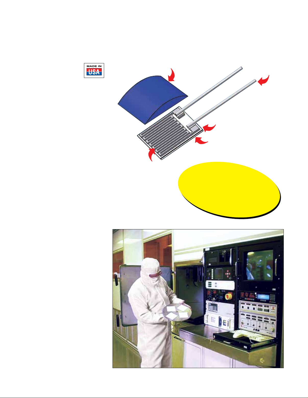
Glass coating over
wire bonds pattern
Platinum thin
film layer
Connection
wires
Connection pad
Ceramic base
OMEGAFILM
Can Be Used As-Is, or Packaged
in a Wide Variety of Sensor Styles. Custom
Packaging Options Are Also Available,
Contact Omega’s Applications
Engineering Department to Discuss
Your Specific Needs.
®
Sensing Elements
C-115
Page 2

Thin Film Interchangeability in °C
Temp °C Class B Class A 1⁄3 DIN (AA)
-50 0.55 — —
-30 0.45 0.21 —
OMEGAFILM
®
elements are manufactured to meet
the requirements of IEC Standard 60751. This
standard uses “Classes” to define the accuracy
and interchangeability for the elements, the
basic resistance vs. temperature characterisitcs,
temperature ranges and other technical
information relating to the OMEGAFILM RTD
elements. Key portions of these requirements
are summarized below.
0 0.30 0.15 0.10
100 0.80 0.35 0.27
150 1.05 0.45 0.36
200 1.30 0.55 —
300 1.80 0.75 —
400 2.30 — —
500 2.80 — —
Accuracy Classes
There are three accuracy “Classes” defined in IEC60751 for film type RTDs, they are: “Class A”, “Class B”,
1
⁄3 DIN (also known as AA).
and
These “Classes” are defined as follows:
Tolerance (°C)
Class A = ±(0.15 + 0.002t)
Class B = ±(0.30 + 0.005t)
Class AA (was
1
⁄3 DIN) = ±(0.1 + 0.0017t)
Temperature Range*
(-30 to 300°C)
(-50 to 500°C)
(0 to 150°C)
t = Temperature °C
C
Note: There is also an industry standard
* Note: The temperature ranges shown are not the temperature ratings for the sensors. Temperature ranges for each product have been
provided, please see the applicable page.
1
⁄10 DIN accuracy not available in film style RTDs.
Equations
Platinum RTD resistance can be calculated using the Callendar-Van Dusen Equation as follows:
For temperatures below 0°C:
Rt = R0 [1 + At + Bt2 + C(t-100)t3]
For temperatures above 0°C, this simplifies to:
Rt = R0 (1 + At + Bt
2
)
where: A = 3.9083 x10⁻³ (C-1)
B = -5.775 x10⁻⁷ (C-2)
C = -4.183 x10
-12
(C-4)
R0 = Resistance at 0°C
t = Temperature in degrees celsius
Maximum Operating Current
The maximum operating current is determined by the amount of electrical current that can be passed through
the element without significant self heating occuring. OMEGA recommends a maximum operating current of 1
milliamp for all of the 100 ohm elements and sensors we supply. Higher or lower currents may be suitable for other
resistances or sensor products, OMEGA recommends testing, for self heating effects before use.
Resistance vs. Temperature Values per IEC60751
Temp Resistance Temp Resistance Temp Resistance
(°C) (Ω) (°C) (Ω) (°C) (Ω)
-200 18.52 150 157.33 450 264.18
-150 39.72 200 175.86 500 280.98
-50 80.31 250 194.10 550 297.49
0 100.00 300 212.05 600 313.71
50 119.40 350 229.72 650 329.64
100 138.50 400 247.09 700 345.28
C-116
Page 3

OMEGAFILM® RTD Elements
(0.008)
Flat Profile Thin Film Platinum
Most
Economical!
for OEM Applications
“F” Series, Sold in Multiples of 100 Pieces
U Very Low Cost
U Flat, Small Profile
U Resistance Meets Requirements of IEC60751
U Temperature Range (See Tolerance Table)
Glass coating over
wire bonds pattern
Connection
wires
U Temperature Coefficient a = 0.00385 Ω/Ω/°C
U 100, 500, and 1000 Ω Configurations
1
U Class A, B, and AA (
⁄3 DIN) Tolerances
U Long-Term Stability—Max R0 Drift 0.4% after
1000 Hours at 500°C
U Vibration Resistance at Least 40 g Acceleration
at 10 to 2000 Hz
(932°F)
Platinum thin
film layer
Connection pad
Ceramic base
U Shock Resistance at 100 g Acceleration with
8 ms Half Sine Wave
Insulation Resistance >10 MΩ at 20°C, >1 MΩ at 500°C
U
U Self Heating 0.4 K/mW at 0°C
U Response Time Water Current (v = 0.4 m/s)
t0.5 = 0.2 s, t0.9 = 0.4 s; Air Stream
(v = 1 m/s) t0.5 = 3.0 s, t0.9 = 9.0 s
U Platinum Clad Nickel Wire Leads
10 L x 0.2 mm D (0.39 x 0.008")
Discount Schedule
1-4 packs .......... Net 10-24 packs .........10%
5-9 packs .......... 5% 25 or more packs .....15%
Tolerance
Tolerance of Temperature
Class Tolerance (°C) resistance at 0°C (V) Range
AA
(1⁄3 DIN)
± (0.1 + 0.0017t) ±0.04 0 to 150°C
A ±(0.15 + 0.002t) ±0.06 -30 to 300°C
B ±(0.3 + 0.005t) ±0.12 -50 to 500°C
To Order visit omega.com/f1500_f2000_f4000 for Pricing and Details
Dimensions in mm Size (mm) Nominal
Model Number (1 mm = 0.03937") W x L x H Resitance (Ω)
F2020-100-B 2.0 x 2.0 x 0.8 100
F2020-100-A 2.0 x 2.0 x 0.8 100
F2020-100-1/3B 2.0 x 2.0 x 0.8 100
F2020-1000-B 2.0 x 2.0 x 0.8 1000
F2020-1000-A 2.0 x 2.0 x 0.8 1000
F2020-1000-1/3B 2.0 x 2.0 x 0.8 1000
F2010-100-B 2.0 x 9.0 x 0.8 100
F2010-100-A 2.0 x 9.0 x 0.8 100
F2010-100-1/3B 2.0 x 9.0 x 0.8 100
F2010-500-B 2.0 x 9.0 x 0.8 500
F2010-1000-B 2.0 x 9.0 x 0.8 1000
F2010-1000-A 2.0 x 9.0 x 0.8 1000
F2010-1000-1/3B 2.0 x 9.0 x 0.8 1000
F4050-100-B 4.0 x 5.0 x 0.8 100
F4050-100-A 4.0 x 5.0 x 0.8 100
F4050-100-1/3B 4.0 x 5.0 x 0.8 100
F4050-500-B 4.0 x 5.0 x 0.8 500
F4050-500-A 4.0 x 5.0 x 0.8 500
F4050-1000-B 4.0 x 5.0 x 0.8 1000
F4050-1000-A 4.0 x 5.0 x 0.8 1000
F4050-1000-1/3B 4.0 x 5.0 x 0.8 100
F1540-100-B 1.5 x 4.0 x 0.8 100
F1540-100-A 1.5 x 4.0 x 0.8 100
F1540-100-1/3B 1.5 x 4.0 x 0.8 100
Sold in multiples of 100 pieces.
Due to the self heating error by the measuring conditions, the measuring current should be limited to a maximum value. We recommend 100 Ω max 1 mA;
500 Ω 0.7 mA; 1000 Ω max 0.3 mA.
Ordering Example: F2020-100-B-100, 100 pieces of 2 x 2 mm 100 Ω Class B tolerance thin film RTD element
(0.031
(0.078
(0.031
(0.078
(0.031
(0.157
(0.031
(0.059
±0.2
0.8
±0.007
)
±0.2
2.0
±0.007
)
(0.078
±0.2
0.8
±0.007
)
±0.2
2.0
±0.007
)
±0.2
0.8
±0.007
)
±0.2
4.0
±0.007
)
(0.196
ø = diameter
±0.2
0.8
±0.007
)
±0.2
1.5
±0.007
)
2.0
9.5
(0.374
5.0
4.0
±0.2
±0.007
±0.2
±0.2
±0.007
±0.2
10
±0.007
10
10
(0.157
±2
)
)
)
±2
10
±2
ø
(0.39
(0.39
ø
±2
(0.39
(0.39
0.2
±0.078
±0.007
C-117
0.2
(0.008)
±0.078
ø
(0.008)
±0.078
0.2
ø
(0.008)
±0.078
)
)
)
0.2
)
)
Page 4

Thin Film RTD Elements
“F” Series for OEM Applications
U Some as Small
as Thermistors
U Flat Packages (0.8 mm Thick)
U a = 0.00385, IEC60751 Curve
U Accuracy Equivalent to That
of Wire-Wound Units
U Better Response Than
Wire-Wound Units of
Equivalent Size
U 100, 500, and 1000 Ω
(See Table Below)
Actual size.
Sold in
Convenient Packs
of 100 Elements
F4050-100-B,
shown larger than actual size.
C
F4050
Actual Size
4.0 x 5.0 x 0.8 mm
F2020
Actual Size
2.0 x 2.0 x 0.8 mm
F4050-100-B, shown larger
than actual size.
F2020-100-B, shown larger
than actual size.
F2010
Actual Size
2.0 x 9.0 x0.8 mm
F1540
Actual Size
1.5 x 4.0 x 0.8 mm
Temp °C Class B Class A 1⁄3 DIN (AA)
-50 0.55 — —
-30 0.45 0.21 —
0 0.30 0.15 0.10
100 0.80 0.35 0.27
150 1.05 0.45 0.36
200 1.30 0.55 —
300 1.80 0.75 —
400 2.30 — —
500 2.80 — —
F2010-100-A, shown larger
than actual size.
F1540-100-1/3B, shown larger
than actual size.
Interchangeability in °C
C-118
 Loading...