

Page 1

Isolated DIN Rail Mount Loop-Powered
2-Wire Signal Conditioners
DRLP Series
U ±0.03% Accuracy (Typical)
U ±0.01% Linearity
U 1500Vrms Transformer Isolation
and 240Vrms Field-Side Protection
U ANSI/IEEE C37.90.1 Transient Protection
U Wide Loop Supply Voltage, 10.8V to 60V
U 5-Pole Low-Pass Filtering
U Up to 160 dB CMR
U 85dB NMR at 60Hz, 80dB at 50Hz
U Protected Against Reverse Connection of
Loop Voltage
U -40 to 80°C (-40 to 176°F) Operating Temperature
U Mounts on DIN Rail EN 50022, 35 x 7.5 or 35 x 15
U CSA C/US Certified (Class I, Division 2, Groups
A, B, C, D)
U CE Compliant
U Manufactured per RoHS Directive 2002/95/EC
The new DRLP Series of loop powered 2-wire
transmitters consists of seven family groups with a
total of 48 transmitter models that interface to a wide
variety of voltage, current, temperature and position
measuring devices. The DRLP Series provides
superior specifications such as ±0.03% accuracy, five
poles of filtering, 1500 Vrms continuous isolation, low
output noise, and much more.
The DRLP Series 2-wire transmitter conditions and
sends analog signals from sensors located in the
“field” to monitoring and control equipment, usually
computers, located thousands of feet away in central
control areas. The DRLP Series accepts a wide
range of inputs, including millivolt, volt, milliamp,
thermocouple, RTD, potentiometer, and slide wire.
It operates on power from a 2-wire signal loop and
modulates the supply current to represent the input
signal within a 4 to 20-milliamp range.
Two-wire transmission loops are very economical
methods for connecting sensors to distant control
rooms. Since the DRLP Series operates from the
signal loop current, no additional, expensive power
and wiring are required. Only low cost, twisted pair
wiring is needed.
DRLP wiring diagram
®
DRLP Series shown
smaller than actual size.
DRLP Loop Drive Capability
The DRLP Series transmitter’s wide range of loop
supply voltage (10.8V to 60V) makes it a versatile
device which can be used in most any current loop.
The maximum loop resistance is determined by
subtracting the transmitter’s minimum loop supply
voltage from the total loop supply voltage and dividing
the result by the maximum loop current (see graph).
The low loop supply voltage of 10.8V allows the DRLP
to be used in applications with low output power supplies
and the high Loop Supply Voltage of 60V allows use in
applications with long distance current loops.
Loop Supply (V)
COMMON SPECIFICATIONS
Input Protection
Continuous: 240 Vrms maximum
Transient: ANSI/IEEE C37.90.1
CMV, Input to Output
Continuous: 1500 Vrms maximum
Transient: ANSI/IEEE C37.90.1
Noise
Output: 100 kHz: 3μArms
Output Range: 4 to 20 mA
Output Protection
Reverse Polarity: Continuous
Over-Voltage: 240 Vrms continuous
Transient: ANSI/IEEE C37.90.1
Loop Supply Voltage: 10.8V to 60V
Loop Supply Sensitivity: ±0.0005%/V
To Order, Call or Shop Online at omega.com
SM
1
Page 2

Turn-On Delay: 400 ms
Environmental
Operating Temperature Range: -40 to 80°C
(-40 to 176°F)
Storage Temperature Range: -40 to 80°C
(-40 to 176°F)
Relative Humidity: 0 to 95% non-condensing
Emissions EN61000-6-4: ISM, Group 1
Radiated, Conducted: Class A
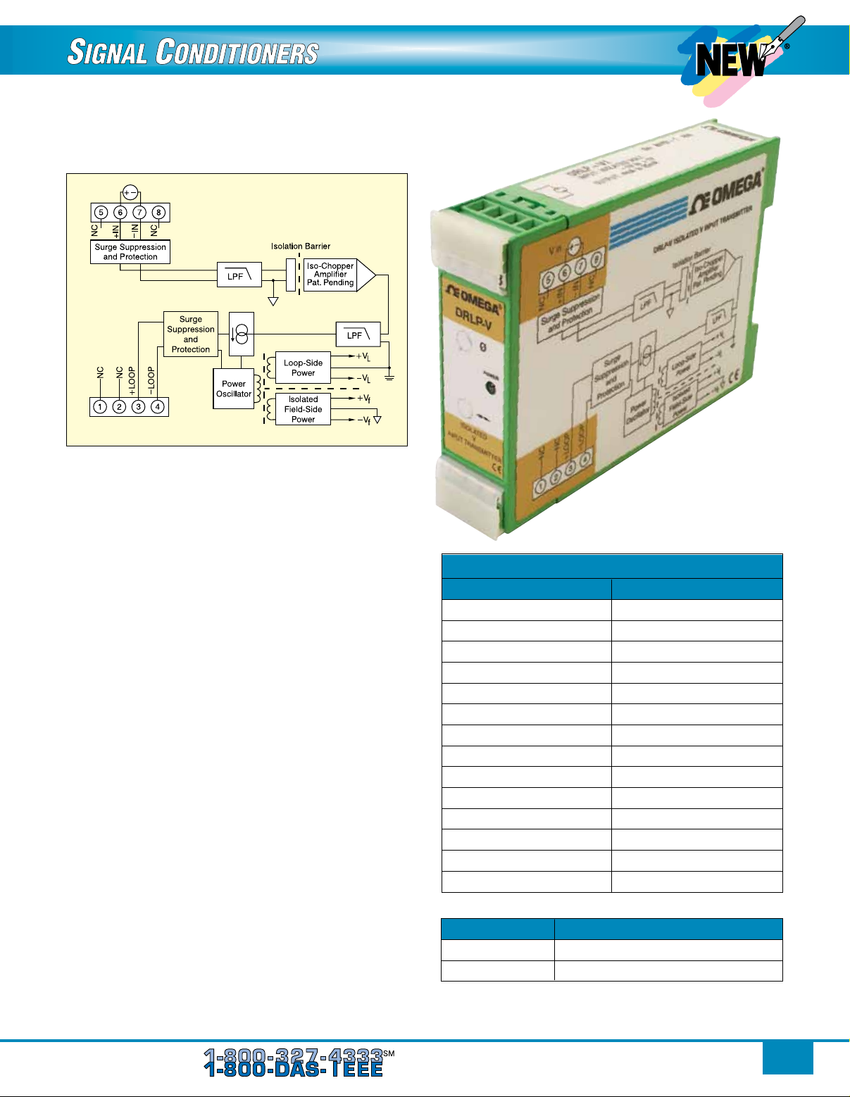
DRLP-MV/DRLP-V
DIN Rail Loop Powered
Analog Voltage Input Transmitters
U Accepts Millivolt and Voltage Level Signals
U Process Current Output
U 1500 Vrms Transformer Isolation
U ANSI/IEEE C37.90.1 Transient Protection
U Input and Output Protected to 240 Vac Continuous
U Up to 60V Loop Voltage
U 160 dB CMR
U 85 dB NMR at 60 Hz, 80 dB at 50 Hz
U ±0.03% Accuracy
U ±0.01% Linearity
U Easily Mounts on Standard DIN Rail
U CSA C/US Certified
U CE Compliant
Immunity EN61000-6-2: ISM, Group 1
RF: Performance A ±0.5% span error
ESD, EFT: Performance B
Mechanical Dimensions: 75 H x 22.5 W x 105 mm D
(2.95 x 0.89 x 4.13")
Mounting: DIN EN 50022 35 x 7.5 mm or
35 x 15 mm rail
Each DRLP-MV and DRLP-V voltage input transmitter
provides a single channel of analog input which
is filtered, isolated, amplified, and converted to a
process current output (Figure 1). Signal filtering is
accomplished with a five-pole filter, which provides
85 dB of normal-mode rejection at 60 Hz and 80 dB at
50 Hz. An anti-aliasing pole is located on the field side
of the isolation barrier, and the other four are on the
process loop side. After the initial field-side filtering,
the input signal is chopped by a proprietary chopper
circuit. Isolation is provided by transformer coupling,
again using a proprietary technique to suppress
transmission of common mode spikes or surges.
Dimensions: mm (inch)
75
(2.95)
22.5
(0.89)
105
(4.13)
DRLP-MV shown actual size.
Special input and output circuits on the DRLP-MV
and DRLP-V transmitters provide protection against
accidental connection of power-line voltages up to
240VAC and against transient events as defined by
ANSI/IEEE C37.90.1. Signal and loop power lines are
secured to the module using screw terminals, which
are in pluggable terminal blocks for ease of system
assembly and reconfiguration.
The modules have excellent stability over time and
do not require recalibration, however, zero and span
settings are adjustable up to ±10% to accommodate
situations where fine-tuning is desired. The
adjustments are made using potentiometers located
under the front panel label and are non-interactive for
ease of use.
2
To Order, Call or Shop Online at omega.com
SM
Page 3
V in
Figure 1: DRLP-MV/DRLP-V Block Diagram
Specifications
Typical at TA = +25°C and +24V Loop Voltage-V
Input Range:
DRLP-MV: ±10 mV to ±100 mV
DRLP-V: ±1V to ±20V
Input Bias Current:
DRLP-MV: ±0.5nA
DRLP-V: ±0.05nA
Input Resistance
Normal
DRLP-MV: 50 MΩ
DRLP-V: 2 MΩ
Power Off
DRLP-MV: 66 kΩ
DRLP-V: 2 MΩ
Overload
DRLP-MV: 66 kΩ
DRLP-V: 2 MΩ
CMR (50 or 60 Hz): 160 dB
NMR: 85 dB at 60 Hz, 80 dB at 50 Hz
Adjustability: ±10% zero and span
Accuracy*: ±0.03%
Conformity: ±0.01%
Stability
Offset: ±20 ppm/°C
Gain: ±80 ppm/°C
Bandwidth, -3dB: 3 Hz
Response Time, 90% Span: 165 ms
Output Limits
Under-Range: 2.8 mA
Over-Range: 29 mA
* Includes linearity, hysteresis and repeatability.
DRLP-V shown actual size.
To Order
Visit omega.com/drlp_series for Pricing and Details
MODEL NO. INPUT RANGE
DRLP-MV1 ±10 mV
DRLP-MV2 ±50 mV
DRLP-MV3 ±100 mV
DRLP-MV4 0 to 10 mV
DRLP-MV5 0 to 50 mV
DRLP-MV6 0 to 100 mV
DRLP-V1 ±1V
DRLP-V2 ±5V
DRLP-V3 ±10V
DRLP-V4 0 to 1V
DRLP-V5 0 to 5V
DRLP-V6 0 to 10V
DRLP-V7 ±20V
DRLP-V8 0 to 20V
Accessories
MODEL NO. DESCRIPTION
RAIL-35-1 35 mm DIN rail, 1 m (3.3') length
RAIL-35-2 35 mm DIN rail, 2 m (6.6') length
Ordering Example: DRLP-V5 isolated DIN rail mount looppowered 2-wire signal conditioner with 0 to 5 V input and 4 to
20 mA output and OCW-1 OMEGECARE 1-year extended warranty
(adds 1 year to standard 1 year warranty).
To Order, Call or Shop Online at omega.com
SM
3
Page 4

DRLP-C
DIN Rail Loop Powered
Analog Current Input Transmitters
U Accepts Milliamp Level Signals
U Process Current Output
U 1500Vrms Transformer Isolation
U ANSI/IEEE C37.90.1 Transient Protection
U Input and Output Protected to 240 Vac Continuous
U Up to 60V Loop Voltage
U 105 dB CMR
U ±0.03% Accuracy
U ±0.01% Linearity
U Easily Mounts on Standard DIN Rail
U CSA C/US Certified
U CE Compliant
Each DRLP-C current input transmitter provides
a single channel of analog input which is filtered,
isolated, amplified, and converted to a process current
output (Figure 1). Signal filtering is accomplished with
a five-pole filter, which provides 80dB per decade of
normal-mode rejection above 100Hz. An anti-aliasing
pole is located on the field side of the isolation barrier,
and the other four are on the process loop side. After
the initial field-side filtering, the input signal is chopped
by a proprietary chopper circuit. Isolation is provided
by transformer coupling, again using a proprietary
technique to suppress transmission of common mode
spikes or surges.
Special input and output circuits on the DRLP-C
transmitters provide protection against accidental
connection of power-line voltages up to 240 Vac and
against transient events as defined by ANSI/IEEE
C37.90.1. Signal and loop power lines are secured
to the module using screw terminals, which are in
pluggable terminal blocks for ease of system assembly
and reconfiguration.
The modules have excellent stability over time and
do not require recalibration, however, zero and span
settings are adjustable up to ±10% to accommodate
situations where fine-tuning is desired. The adjustments
are made using potentiometers located under the front
panel label and are non-interactive for ease of use.
I in
Figure 1: DRLP-C Block Diagram
DRLP-C shown actual size.
Specifications
Typical at TA=+25°C and +24V Loop Voltage
Input Range: 0 to 20 or 4 to 20 mA
Current Conversion Resistor: 50.00W
CMR (50 or 60 Hz): 105 dB
NMR (-3 dB at 100 Hz): 80 dB/decade above 100 Hz
Adjustability: ±10% zero and span
Accuracy*: ±0.03%
Conformity: ±0.01%
Stability
Offset: ±30 ppm/°C
Gain: ±90 ppm/°C
Bandwidth, -3 dB: 100 Hz
Response Time, 90% Span: 5 ms
Output Limits
Under-Range: 2.8 mA
Over-Range: 29 mA
* Includes linearity, hysteresis and repeatability.
To Order
Visit omega.com/drlp_series for Pricing and Details
MODEL NO. INPUT RANGE
DRLP-C1 4 to 20 mA
DRLP-C2 0 to 20 mA
Accessories
MODEL NO. DESCRIPTION
RAIL-35-1 35 mm DIN rail, 1 m (3.3') length
RAIL-35-2 35 mm DIN rail, 2 m (6.6') length
Ordering Example: DRLP-C1 isolated DIN rail mount loop-powered
2-wire signal conditioner with 4 to 20 mA input and 4 to 20 mA output
and OCW-1 OMEGACARE 1-year extended warranty (adds 1 year to
standard 1 year warranty).
4
To Order, Call or Shop Online at omega.com
SM
Page 5

DRLP-RTD
DIN Rail Loop Powered
Linearized 2- or 3-Wire
RTD Input Transmitters
U Interfaces to 100Ω Platinum or 120Ω Nickel RTDs
U Linearizes RTD Signal
U Process Current Output
U 1500Vrms Transformer Isolation
U ANSI/IEEE C37.90.1 Transient Protection
U Input and Output Protected to 240 Vac Continuous
U Up to 60V Loop Voltage
U 160 dB CMR
U 85 dB NMR at 60 Hz, 80 dB at 50 Hz
U ±0.1% Accuracy
U ±0.025% Conformity
U Easily Mounts on Standard DIN Rail
U CSA C/US Certified
U CE Compliant
Each DRLP-RTD RTD input transmitter provides
a single channel of RTD input which is filtered,
isolated, amplified, linearized, and converted to a
process current output (Figure 1). Signal filtering is
accomplished with a five-pole filter, which provides
85dB of normal-mode rejection at 60Hz and 80dB at
50Hz. An anti-aliasing pole is located on the field side
of the isolation barrier, and the other four are on the
process loop side. After the initial field-side filtering,
the input signal is chopped by a proprietary chopper
circuit. Isolation is provided by transformer coupling,
again using a proprietary technique to suppress
transmission of common mode spikes or surges.
RTD excitation is provided from the transmitter using
a precision current source. The excitation currents
are very small (0.26mA max for 100Ω Pt and 120Ω Ni)
which minimizes self-heating of the RTD. Linearization
is achieved by creating a non-linear transfer function
through the module itself. This non-linear transfer
function is configured at the factory and is designed
to be equal and opposite to the specific RTD nonlinearity. Lead compensation is achieved by matching
two current paths thus canceling the effects of lead
resistance.
The specifications listed are for a 3-wire connection.
A 2-wire connection of the RTD to the module is also
possible and is achieved by adding a jumper between
pin 5 (+EXC) and pin 6 (+IN) on the terminal block and
connecting the RTD leads between pin 6 (+IN) and
pin 7 (-IN). The 2-wire connection nullifies the lead
resistance compensation feature of the module.
Special input and output circuits on the DRLP-RTD
transmitters provide protection against accidental
connection of power-line voltages up to 240VAC and
against transient events as defined by ANSI/IEEE
C37.90.1. Signal and loop power lines are secured
to the module using screw terminals, which are in
pluggable terminal blocks for ease of system assembly
and reconfiguration.
DRLP-RTD shown actual size.
The modules have excellent stability over time and
do not require recalibration, however, zero and span
settings are adjustable up to ±3% to accommodate
situations where fine-tuning is desired. The
adjustments are made using potentiometers located
under the front panel label and are non-interactive for
ease of use.
Specifications
Typical at TA = 25°C and 24V Loop Voltage
DRLP-RTD
Input Range: -200 to 850°C (-328 to 1562°F)
(100Ω Pt); -80 to 320°C (-112 to 608°F) (120Ω Ni)
Input Resistance
Normal: 50 MΩ
Power Off: 66 kΩ
Overload: 66 kΩ
CMR (50 or 60 Hz): 160 dB
NMR: 85 dB at 60 Hz, 80 dB at 50 Hz
Adjustability: ±3% zero and span
Accuracy: See ordering information
Conformity: ±0.025%
Stability
Offset: ±50 ppm/°C
Gain: ±100 ppm/°C
Sensor Excitation Current: 0.260 mA
Lead Resistance Effect: ±0.02°C/Ω
Bandwidth, -3dB: 3 Hz
Response Time, 90% Span: 165 ms
Output Limits
Under-Range: 3 mA
Over-Range: 29 mA
To Order, Call or Shop Online at omega.com
SM
5
Page 6

Figure 1: DRLP-RTD Block Diagram
**RTD Standards
Alpha
Type Coefficient DIN JIS IEC
100 Ω Pt 0.00385 DIN 43760 JIS C 1604-1989 IEC 751
120 Ω Ni 0.00672 – – –
To Order
MODEL NO.
100 Ω Pt ** INPUT RANGE ACCURACY*
DRLP-RTD1 -100 to 100°C ±0.1% span
(-148 to 212°F) ±0.2°C
DRLP-RTD2 0 to 100°C ±0.1% span
(32 to 212°F) ±0.1°C
DRLP-RTD3 0 to 200°C ±0.1% span
(32 to 392°F) ±0.2°C
DRLP-RTD4 0 to 600°C ±0.1% span
(32 to 1112°F) ±0.6°C
DRLP-RTD5 0 to 400°C ±0.1% span
(32 to 752°F) ±0.4°C
120 Ω Ni **
DRLP-RTD6 0 to 300°C ±0.1% span
(32 to 572°F) ±0.3°C
* Includes conformity, hysteresis and repeatability.
Visit omega.com/drlp_series for Pricing and Details
Accessories
MODEL NO. DESCRIPTION
RAIL-35-1 35 mm DIN rail, 1 m (3.3') length
RAIL-35-2 35 mm DIN rail, 2 m (6.6') length
Ordering Example: DRLP-RTD5 isolated DIN rail mount looppowered 2-wire signal conditioner with 100 Ω Pt RTD input and 4 to
20 mA output and OCW-1 OMEGACARE 1 year extended warranty
(adds 1 year to standard 1 year warranty).
DRLP-P
DIN Rail Loop Powered
Potentiometer Input Transmitters
U Interfaces to Potentiometers up to 10 kΩ
U Process Current Output
U 1500 Vrms Transformer Isolation
U ANSI/IEEE C37.90.1 Transient Protection
U Input and Output Protected to 240 Vac Continuous
U Up to 60V Loop Voltage
U 160 dB CMR
U 85 dB NMR at 60 Hz, 80 dB at 50 Hz
U ±0.03% Accuracy
U ±0.01% Linearity
U Easily Mounts on Standard DIN Rail
U CSA C/US Certified
U CE Compliant
Each DRLP-P potentiometer input transmitter
provides a single channel of potentiometer input
which is filtered, isolated, amplified, and converted to
a process current output (Figure 1). Signal filtering is
accomplished with a five-pole filter, which provides
85dB of normal-mode rejection at 60Hz and 80dB at
50Hz. An anti-aliasing pole is located on the field side
of the isolation barrier, and the other four are on the
process loop side. After the initial field-side filtering,
the input signal is chopped by a proprietary chopper
circuit. Isolation is provided by transformer coupling,
again using a proprietary technique to suppress
transmission of common mode spikes or surges.
DRLP-P shown actual size.
Potentiometer excitation is provided from the
transmitter using a precision current source. The
excitation current is small (less than 0.26mA) which
minimizes self-heating of the potentiometer. Lead
compensation is achieved by matching two current
paths which cancels the effects of lead resistance.
6
To Order, Call or Shop Online at omega.com
SM
Page 7

Special input and output circuits on the DRLP-P
transmitters provide protection against accidental
connection of power-line voltages up to 240 Vac and
against transient events as defined by ANSI/IEEE
C37.90.1. Signal and loop power lines are secured
to the module using screw terminals, which are in
pluggable terminal blocks for ease of system assembly
and reconfiguration.
The modules have excellent stability over time and
do not require recalibration, however, zero and span
settings are adjustable up to ±10% to accommodate
situations where fine-tuning is desired. The adjustments
are made using potentiometers located under the front
panel label and are non-interactive for ease of use.
Figure 1: DRLP-P Block Diagram
CMR (50 or 60 Hz): 160 dB
NMR: 85 dB at 60 Hz, 80 dB at 50 Hz
Adjustability: ±10% Zero and Span
Accuracy*: ±0.03%
Conformity: ±0.01%
Stability
Offset: ±50 ppm/°C
Gain: ±100 ppm/°C
Sensor Excitation Current: 0.26 mA; 100Ω, 500Ω
sensor;
0.13 mA; 1 kΩ Sensor; 0.065 mA; 10 kΩ sensor
Lead Resistance Effect: ±0.01Ω/Ω; 100Ω, 500Ω,
1 kΩ sensor: ±0.02Ω/Ω; 10 kΩ sensor
Bandwidth, -3dB: 3Hz
Response Time, 90% Span: 165ms
Output Limits
Under-Range: 3 mA
Over-Range: 29 mA
* Includes linearity, hysteresis and repeatability.
Specifications
Typical at TA=+25°C and +24V Loop Voltage
Input Range: 0Ω to 10 kΩ
Input Resistance
Normal: 50M Ω
Power Off: 66 kΩ
Overload: 66 kΩ
DRLP-ITC
DIN Rail Loop Powered Non-Linearized
Thermocouple Input Transmitters
U Interfaces to Types J, K, T, E, R, S, B, and
N Thermocouples
U Process Current Output
U 1500Vrms Transformer Isolation
U ANSI/IEEE C37.90.1 Transient Protection
U Input and Output Protected to 240 Vac Continuous
U Up to 60V Loop Voltage
U 160 dB CMR
U 85 dB NMR at 60 Hz, 80 dB at 50 Hz
U ±0.05% Accuracy
U ±0.01% Linearity
U Easily Mounts on Standard DIN Rail
U CSA C/US Certified
U CE Compliant
To Order
MODEL NO. INPUT RANGE
DRLP-P1 0 to 100Ω
DRLP-P2 0 to 500Ω
DRLP-P3 0 to 1 kΩ
DRLP-P4 0 to 10 kΩ
Visit omega.com/drlp_series for Pricing and Details
Accessories
MODEL NO. DESCRIPTION
RAIL-35-1 35 mm DIN rail, 1 m (3.3') length
RAIL-35-2 35 mm DIN rail, 2 m (6.6') length
Ordering Example: DRLP-P3 isolated DIN rail mount
loop-powered 2-wire signal conditioner with
0 to 1 kΩ input and 4 to 20 mA output
and OCW-1 OMEGACARE 1-year
extended warranty (adds 1
year to standard 1-year
warranty).
DRLP-ITC shown actual size.
To Order, Call or Shop Online at omega.com
SM
7
Page 8

Each DRLP-ITC non-linearized thermocouple input
transmitter provides a single channel of thermocouple
input which is filtered, isolated, amplified, and
converted to a process current output (Figure 1).
Signal filtering is accomplished with a five-pole filter,
which provides 85dB of normal-mode rejection at
60Hz and 80dB at 50Hz.An anti-aliasing pole is
located on the field side of the isolation barrier, and
the other four are on the process loop side. After the
initial field-side filtering, the input signal is chopped
by a proprietary chopper circuit. Isolation is provided
by transformer coupling, again using a proprietary
technique to suppress transmission of common mode
spikes or surges.
The DRLP-ITC can interface to eight industry standard
thermocouple types: J, K, T, E, R, S, B and N. Each
transmitter is cold-junction compensated to correct for
parasitic thermocouples formed by the thermocouple
wire and screw terminals on the transmitter. Upscale
open thermocouple detection is provided by circuitry.
Downscale indication can be implemented by installing
a 47M Ω, ±20% resistor between screw terminals
6 (+IN) and 8 (-EXC) on the input terminal block.
Special input and output circuits on the DRLP-ITC
transmitters provide protection against accidental
connection of power-line voltages up to 240VAC
and against transient events as defined by ANSI/
IEEE C37.90.1. Loop power lines are secured to the
module using screw terminals, which are in pluggable
terminal blocks for ease of system assembly and
reconfiguration. Transmitter zero and span settings
are adjustable up to ±10%. The adjustments are made
using potentiometers located under the front panel
label and are non-interactive for ease of use.
Specifications
Typical at TA=+25°C and +24V Loop Voltage
Input Range: Standard thermocouple temperature
limits as per NIST monograph 175, ITS-90
Input Bias Current: -25nA
Input Resistance
Normal: 50M Ω
Power Off: 66 kΩ
Overload: 66 kΩ
CMR (50 or 60 Hz): 160 dB
NMR: 85 dB at 60 Hz, 80 dB at 50 Hz
Adjustability: ±10% zero and span
Accuracy: See ordering information
Stability
Offset: ±40 ppm/°C
Gain: ±60 ppm/°C
Cold Junction Compensation
Accuracy, 25°C: ±0.25°C
Accuracy, 0 to 50°C: ±0.50°C
Accuracy, -40 to 80°C: ±1.25°C
Open Input Response: Upscale
Open Input Detection Time: < 5s
Bandwidth, -3dB: 3Hz
Response Time, 90% Span: 165 ms
Output Limits
Under-Range: 2.8 mA
Over-Range: 29 mA
Figure 1: DRLP-ITC Block Diagram
To Order
MODEL NO. TYPE RANGE ACCURACY*
DRLP-ITC-J J -100 to 760°C ±0.05% span
(-148 to 1400°F) ±0.43°C
DRLP-ITC-K K -100 to 1350°C ±0.05% span
(-148 to 2462°F) ±0.73°C
DRLP-ITC--T T -100 to 400°C ±0.05% span
(-148 to 752°F) ±0.25°C
DRLP-ITC-E E 0 to 900°C ±0.05% span
(32 to 1652°F) ±0.45°C
DRLP-ITC-R R 0 to 1750°C ±0.05% span
(32 to 3182°F) ±0.88°C
DRLP-ITC-S S 0 to 1750°C ±0.05% span
(32 to 3182°F) ±0.88°C
DRLP-ITC--B B 0 to 1800°C ±0.05% span
(32 to 3272°F) ±0.90°C
DRLP-ITC-N N -100 to 1300°C ±0.05% span
(-148 to 2372°F) ±0.70°C
* Includes conformity, hysteresis, repeatability and CJC error.
Visit omega.com/drlp_series for Pricing and Details
TC INPUT
Accessories
MODEL NO. DESCRIPTION
RAIL-35-1 35 mm DIN rail, 1 m (3.3') length
RAIL-35-2 35 mm DIN rail, 2 m (6.6') length
Ordering Example: DRLP-ITC-K non-linearized solated DIN
rail mount loop-powered 2-wire signal conditioner with type K
thermocouple input and 4 to 20 mA output and OCW-1 OMEGACARE
1-year extended warranty (adds 1 year to standard 1-year warranty).
8
To Order, Call or Shop Online at omega.com
SM
Page 9

DRLP-LTC
DIN Rail Loop Powered
Linearized Thermocouple
Input Transmitters
U Interfaces to Types J, K, T, E, R, S, B,
and N Thermocouples
U Linearizes Thermocouple Signal
U Process Current Output
U 1500Vrms Transformer Isolation
U ANSI/IEEE C37.90.1 Transient Protection
U Input and Output Protected to 240 Vac Continuous
U Up to 60V Loop Voltage
U 160 dB CMR
U 85 dB NMR at 60 Hz, 80 dB at 50 Hz
U ±0.10% Accuracy
U Easily Mounts on Standard DIN Rail
U CSA C/US Certified
U CE Compliant
Each DRLP-LTC thermocouple input transmitter
provides a single channel of thermocouple input which
is filtered, isolated, amplified, linearized, and converted
to a process current output (Figure 1). Signal filtering
is accomplished with a five-pole filter, which provides
85dB of normal-mode rejection at 60Hz and 80dB at
50Hz. An anti-aliasing pole is located on the field side
of the isolation barrier, and the other four are on the
process loop side. After the initial field-side filtering,
the input signal is chopped by a proprietary chopper
circuit. Isolation is provided by transformer coupling,
again using a proprietary technique to suppress
transmission of common mode spikes or surges.
Figure 1: DRLP-LTC Block Diagram
DRLP-LTC shown actual size.
Linearization is achieved by creating a non-linear
transfer function through the module itself. This nonlinear transfer function is configured at the factory
and is designed to be equal and opposite to the
thermocouple non-linearity.
The DRLP-LTC can interface to eight industry standard
thermocouple types: J, K, T, E, R, S, B and N. Each
transmitter is cold-junction compensated to correct for
parasitic thermocouples formed by the thermocouple
wire and screw terminals on the transmitter. Upscale
open thermocouple detection is provided by circuitry.
Downscale indication can be implemented by installing
a 47MΩ, ±20% resistor between screw terminals 6
(+IN) and 8 (-EXC) on the input terminal block.
Special input and output circuits on the DRLP-LTC
transmitters provide protection against accidental
connection of power-line voltages up to 240VAC
and against transient events as defined by ANSI/
IEEE C37.90.1. Loop power lines are secured to the
module using screw terminals, which are in pluggable
terminal blocks for ease of system assembly and
reconfiguration. Transmitter zero and span settings
are adjustable up to ±3%. The adjustments are made
using potentiometers located under the front panel
label and are non-interactive for ease of use.
To Order, Call or Shop Online at omega.com
SM
9
Page 10

Specifications
Typical at TA=+25°C and +24V Loop Voltage
Input Range: Standard thermocouple temperature
limits as per NIST monograph 175, ITS-90
Input Bias Current: -25 nA
Input Resistance
Normal: 50 MΩ
Power Off: 66 kΩ
Overload: 66 kΩ
CMR (50Hz or 60Hz): 160 dB
NMR: 85 dB at 60 Hz, 80 dB at 50 Hz
Adjustability: ±3% zero and span
Accuracy: See ordering information
Stability
Offset: ±60 ppm/°C
Gain: ±80 ppm/°C
Cold Junction Compensation
Accuracy, 25°C: ±0.25°C
Accuracy, 0 to 50°C: ±0.50°C
Accuracy, -40 to 80°C: ±1.25°C
Open Input Response: Upscale
Open Input Detection Time: < 5s
Bandwidth, -3 dB: 3Hz
Response Time, 90% Span: 165 ms
Output Limits
Under-Range: 2.8 mA
Over-Range: 29 mA
Accessories
MODEL DESCRIPTION
RAIL-35-1 35 mm DIN rail, 1 m (3.3') length
RAIL-35-2 35 mm DIN rail, 2 m (6.6') length
Ordering Example: DRLP-LTC-K1 linearized isolated DIN
rail mount loop-powered 2-wire signal conditioner with type K
thermocouple input [0 to 1000°C (32 to 1832°F) temperature range]
and 4 to 20 mA output and OCW-1 OMEGACARE 1 year extended
warranty.
DRLP Series shown
smaller than actual size.
To Order
TC INPUT
MODEL NO. TYPE RANGE ACCURACY*
DRLP-LTC-J1 0 to 760°C ±0.1% span
(32 to 1400°F) ±0.76°C
DRLP-LTC-J2 J -100 to 300°C ±0.1% span
(-148 to 572°F) ±0.40°C
DRLP-LTC-J3 0 to 500°C ±0.1% span
(32 to 932°F) ±0.50°C
DRLP-LTC-K1 0 to 1000°C ±0.1% span
(32 to 1832°F) ±1.00°C
DRLP-LTC-K2 0 to 500°C ±0.1% span
(32 to 932°F) ±0.50°C
DRLP-LTC-K3 K -100 to 1350°C ±0.1% span
(-148 to 2462°F) ±1.45°C
DRLP-LTC-K4 0 to 1200°C ±0.1% span
(32 to 2192°F) ±1.20°C
DRLP-LTC-T1 -100 to 400°C ±0.1% span
(-148 to 752°F) ±0.50°C
DRLP-LTC-T2 0 to 200°C ±0.1% span
(32 to 392°F) ±0.20°C
DRLP-LTC-E E 0 to 1000°C ±0.1% span
(32 to 1832°F) ±1.00°C
DRLP-LTC-R R 500 to 1750°C ±0.1% span
(932 to 3182°F) ±1.25°C
DRLP-LTC-S S 500 to 1750°C ±0.1% span
(932 to 3182°F) ±1.25°C
DRLP-LTC-B B 500 to 1800°C ±0.1% span
(932 to 3272°F) ±1.30°C
DRLP-LTC-N N -100 to 1300°C ±0.1% span
(-148 to 2372°F) ±1.40°C
* Includes conformity, hysteresis, repeatability and CJC error.
Visit omega.com/drlp_series for Pricing and Details
10
To Order, Call or Shop Online at omega.com
SM
 Loading...