

Page 1
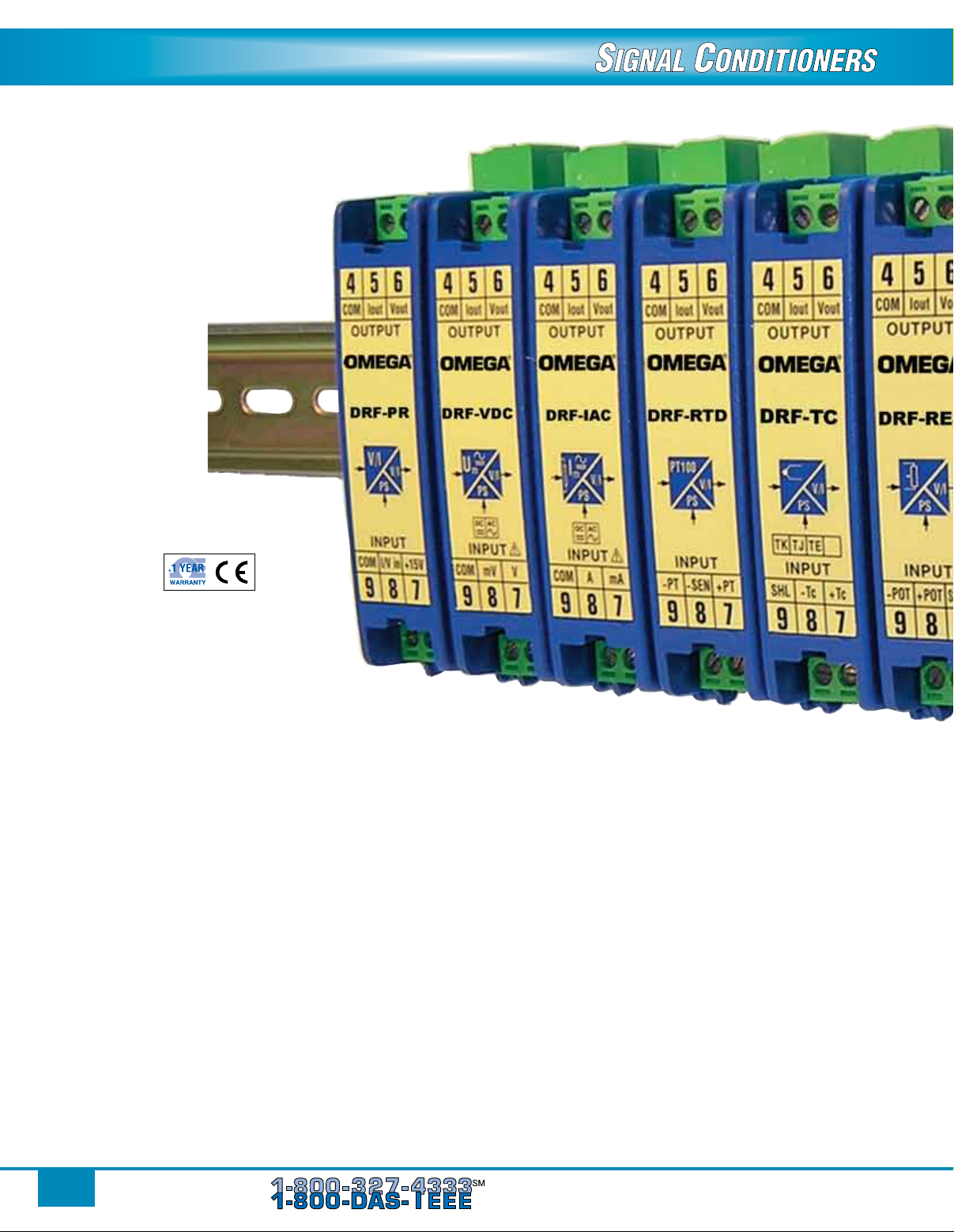
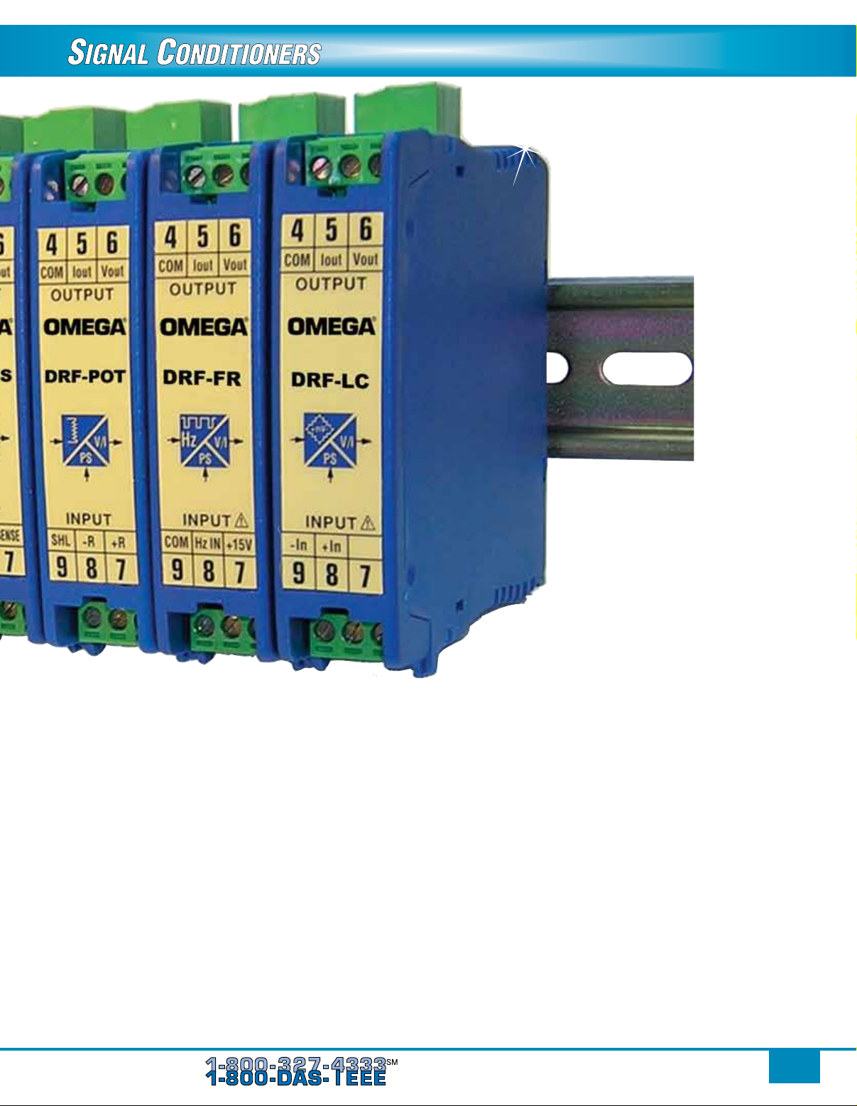
DIN Rail Mount Configurable Signal Conditioners
DRF Series
U Voltage, Current, Frequency, Resistance,
Potentiometer, Thermocouple, RTD
and Load Cell Input Modules
U Field Configurable Signal Ranges
U Provides up to 3500 Veff Isolation Between
Input and Output and Power (Isolation
is Model Specific)
U Compatible with Standard 35 mm DIN Rail
The DRF series DIN rail signal conditioners are
designed to accept a broad range of input signals,
such as ac and dc voltage and current, frequency,
temperature (thermocouple and RTD), and process
transducers, and provide standard process outputs
of either 4 to 20 mA, or 0 to 10 Vdc. The DRF series
feature a modern housing design, that is easily
mounted on standard 35 mm DIN rails. Connections
are safely and securely made through pluggable screw
terminal connectors, with input and output connections
on the opposite sides of the module.
Functionality
The DRF series are designed to maximize
functionality. The front door of the housing provides
easy access to span and offset potentiometers
which may be used to field adjust the input and
output signal range.
Isolation
The input, output and power circuits are isolated by
3500 volts of galvanic isolation. The isolation protects
against potentially damaging voltages from passing
through the signal conditioners into connected
systems. The isolation also provides improved
measurement accuracy by minimizing the effects of
ground loops and electrical noise.
Outputs
Each DRF series signal conditioner is available with
current and voltage output (only one may be used at
a time). Available output types include 4 to 20 mA or
0 to 10 Vdc. Although pre-configured before shipping
from the factory, the output may be changed through
an internal jumper change.
Standard outputs are linear and proportional to the
signal input. Thermocouple input modules feature
special circuitry to linearize the output to the actual
temperature rather than the non-linear signal produced
by thermocouple sensors.
1
To Order, Call or Shop Online at omega.com
SM
Page 2
SPECIFICATIONS
(Common to all Models)
Power: 24 Vdc ±10%, 230 Vac ±10% 50/60 Hz,
115 Vac ±10% 50/60 Hz
Power Consumption: <3.8 VA
Output: 4 to 20 mA and 0 to 10 Vdc
Maximum Voltage Output: 11 Vdc approx.
Minimum Voltage Output: -1 Vdc approx.
Minimum Load Resistance (Voltage): ≥1 KΩ
Maximum Current Output: 22 mA approx.
Maximum Current Output: -1.5 mA approx.
Maximum Load Resistance (current): ≤400Ω
Accuracy: <0.2% or <0.3% depending on model
Linearity: <0.1% or <0.2% depending on model
Thermal Drift: <150 ppm/°C or 250 ppm/°C typical
depending on model
Response Time: 70 mS (Process and DC input
models); 250 mS (Temperature and AC input models)
Isolation*:
Input to Output: 3500 Veff
Power to Input: 3500 Veff
Power to Output: 3500 Veff (for AC powered
models), 1K Veff (for dc powered models)
Electrical Connections: Plug-in screw terminals
Protection: IP-30
MECHANICAL DIMENSIONS
Weight:
(DC Powered): 120 g (4.2 oz)
(AC Powered): 200 g (7 oz)
Dimensions:
(DC Powered Models): 110 H x 22.5 W x 93 mm D
(4.3 x 0.9 x 3.7")
(AC Powered Models):
110 H x 37 W x 93 mm D (4.3 x 1.46 x 3.7")
Operating Temperature: 0 to 60°C (32 to 140°F)
Storage Temperature: -20 to 70°C (-4 to 158°F)
*Tested True RMS, 60 sec. leak <1 mA
To Order, Call or Shop Online at omega.com
SM
2
Page 3
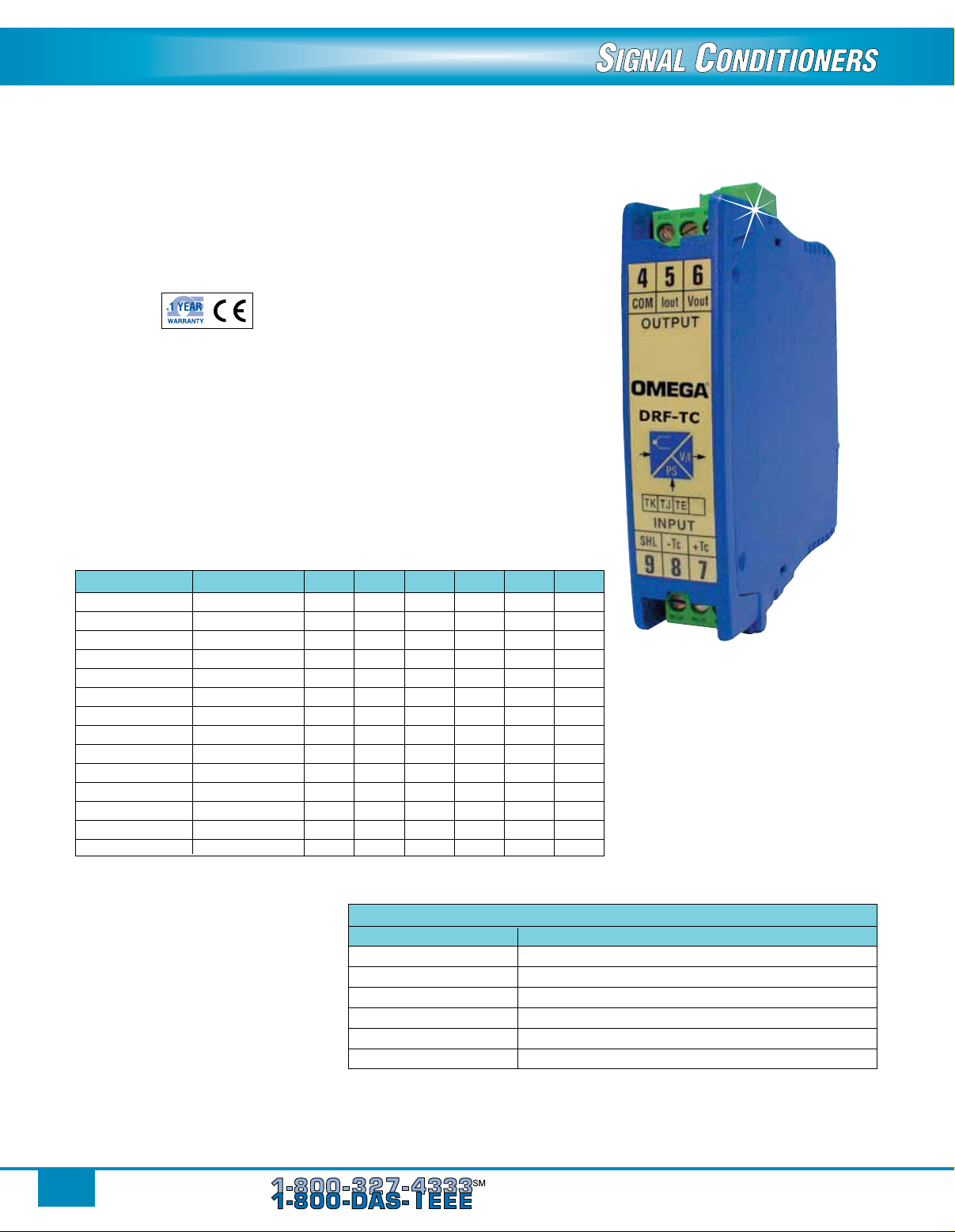
Thermocouple Input Signal Conditioner
The DRF-TC thermocouple signal
conditioners accept thermocouple
input and provide a linearized and
isolated 0 to 10 Vdc or 4 to 20 mA
output. Models are available with
DRF-TC
U Models for J, K, E, T, R
and S Thermocouples
U Accuracy 0.3%
U 250 ms Response Time
U Upscale Break Protection
U Linearized Output
U Galvanic Isolation Between
Input, Output and Power
Input Range Table
Range Code Range J K T E R S
0/100C 0 to 100°C X
0/150C 0 to 150°C X X
0/175C 0 to 175°C X
0/200C 0 to 200°C X
0/250C 0 to 250°C X X
0/300C 0 to 300°C X X
0/400C 0 to 400°C X X X
0/500C 0 to 500°C X
0/700C 0 to 700°C X X
0/800C 0 to 800°C X
0/1200C 0 to 1200°C X
0/1600C 0 to 1600°C X
850/1700C 850 to 1700°C X
Minimum Span* 85°C 85°C 100°C 85°C 100°C 100°C
* Custom ranges may be obtained by adjusting on-board zero and span potentiometers.
The minimum range is limited by the minimum span specification.
three different power options, 24Vdc,
120 Vac and 240 Vac.
The DRF-TC are ideally suited for
industrial applications. All models
mount on a standard 35 mm DIN
rail and provide galvanic isolation
between input, output and power
up to 3500 Veff (model specific).
To insure maximum measurement
accuracy the units feature cold
junction compensation, 0.2% linearity
and less than 0.1˚C/1˚C thermal
drift due to compensation. Module
response time is 250 ms or less.
DRF-TCJ-115VAC-0/400C-4/20,
shown larger than actual size
Specifications
Accuracy: <0.3% full scale
Linearity: <0.2% full scale
Thermal Drift: <250 ppm/°C typical
Thermocouple CJC Drift: 0.1°C/°C
Response Time: <250mS
(90% of signal)
Input Impedance: 1 MΩ
Over Voltage Protection: 10 V
Thermocouple Input
3
To Order, Call or Shop Online at omega.com
Thermocouple
probe types:
J, K, E, T, R, S
(one model
for each
thermocouple
type
To Order Visit omega.com/drf_series for Pricing and Details
Model No. Description
DRF-TCJ-(*)-(**)-(***) Signal conditioner for J type thermocouple
DRF-TCK-(*)-(**)-(***) Signal conditioner for K type thermocouple
DRF-TCT-(*)-(**)-(***) Signal conditioner for T type thermocouple
DRF-TCE-(*)-(**)-(***) Signal conditioner for E type thermocouple
DRF-TCR-(*)-(**)-(***) Signal conditioner for R type thermocouple
DRF-TCS-(*)-(**)-(***) Signal conditioner for S type thermocouple
* Specify power, “24Vdc” for 24 Vdc power, “115 Vac” for 115Vac power or “230Vac”
for 230 Vac power
** Specify range code from the Input Range Table
*** Specify output, “4/20” for 4 to 20 mA output or “0/10” for 0 to 10 Vdc output
Ordering Example: DRF-TCJ-115VAC-0/400C-4/20, signal conditioner for
a J thermocouple with a 0 to 400°C input range, 4 to 20 mA output and 115 Vac power.
SM
Page 4

RTD Input Signal Conditioner
DRF-RTD
U 100 Ω Platinum (Pt) RTD
Element, 0.00385 Curve
U 2 or 3 Wire Configuration
U 0.2% Accuracy
U Cable Resistance
Compensation up to 10Ω
U Upscale Break Protection
U Response Time <250 mS
U Galvanic Isolation Between
Input, Output and Power
The DRF-RTD RTD signal
conditioners accept 2 or 3 wire
100 platinum RTDs as input and
provide an isolated 0 to 10 Vdc
or 4 to 20 mA output. Models are
available with three different power
options, 24 Vdc, 120 Vac and
240 Vac.
The DRF-RTD are ideally suited for
industrial applications. All models
mount on a standard 35 mm DIN
rail and provide galvanic isolation
between input, output and power up
to 3500 Veff (model specific). Module
response time is 250 mS or less.
Specifications
RTD: 2 or 3 wire 100Ω platinum
RTD, Ω=0.00385
Accuracy: <0.2% full scale
Linearity: <0.1% full scale
Thermal Drift: 250 ppm/°C typical
Response Time: <250mS
(90% of signal)
RTD Excitation: 1 Vdc
Input Impedance: Measured
with a “Wheatstone” bridge.
Bridge to positive through a 100Ω
resistance, Bridge to negative
through a 10 KΩ resistance
DRF-RTD-24VDC-0/100C-0/10,
shown larger than actual size.
Input Range Table
Range Code Range
-25/75C -25 to 75°C
-50/150C -50 to 150°C
0/100C 0 to 100°C
0/200C 0 to 200°C
0/300C 0 to 300°C
0/450C 0 to 450°C
0/600C 0 to 600°C
* Custom ranges may be obtained by adjusting
on-board zero and span potentiometers. The
minimum range is 0 to 50°C, maximum range
is 0 to 600°C (32 to 1112°F).
To Order
Visit omega.com/drf_series for Pricing and Details
2-Wire
RTD Input
Model No. Description
DRF-RTD-(*)-(**)-(***) Signal conditioner for 100Ω Pt RTD
* Specify power, “24Vdc” for 24 Vdc power, “115Vac” for 115 Vac power or “230Vac” for 230 Vac power
** Specify range code from the Input Range Table
*** Specify output, “4/20” for 4 to 20 mA output or “0/10” for 0 to 10 Vdc output
Ordering Example: DRF-RTD-24VDC-0/100C-0/10, signal conditioner for an RTD with a
0 to 100°C input range, 0 to 10 Vdc output and 24 Vdc power.
3-Wire
RTD Input
To Order, Call or Shop Online at omega.com
SM
4
Page 5

DC and AC Voltage Input Signal Conditioners
DRF-VDC,
DRF-VAC
U AC/DC Voltage Input Ranges
from 60 mV to 650 V
U Accuracy 0.3%
U Response Time for
DC Signals, 70 mS
U Response Time for
AC Signals, 250 mS
U Over Range Protection
for Voltage Inputs
U High Impedance
Voltage Inputs
U Galvanic Isolation Between
Input, Output and Power
The DRF-VDC and the DRF-VAC
voltage signal conditioners accept
dc and ac voltages respectively and
provide an isolated 0 to 10 Vdc or
4 to 20 mA output. Models are
available with three different
power options, 24 Vdc, 120 Vac
and 240 Vac.
DRF-VDC-230VAC-300V-4/20,
shown larger than actual size.
The DRF-VDC and DRF-VAC
are ideally suited for industrial
applications. All models mount on a
standard 35mm DIN rail and provide
galvanic isolation between input,
output and power up to 3500 Veff
(model specific).
Specifications
Accuracy: <0.2% full scale
Linearity: <0.1% full scale
Thermal Drift: 150 ppm/°C typical
(max <200 ppm/°C)
Response Time
(dcV Signal Input Models):
< 70 mS (90% of signal)
at 20 Hz -3 dB
Response Time (acV signal input
models): <250 mS (90% of signal)
Input Impedance: 1 MΩ
for ranges < 1 V, 10 MΩ
for ranges > 1 V
Over Range Protection:
1000 V for ranges greater than
100 V, 500 V for ranges less
than or equal to 100 V
Input Range Table
Range Code DRF Vdc Range DRF Vac Range
75MV 0 to 75 mVdc 0 to 75 mVac
150MV 0 to 150 mVdc 0 to 150 mVac
300MV 0 to 300 mVdc 0 to 300 mVac
650MV 0 to 650 mVdc 0 to 650 mVac
1V 0 to 1 Vdc 0 to 1 Vac
7.5V 0 to 7.5 Vdc 0 to 7.5 Vac
15V 0 to 15 Vdc 0 to 15 Vac
65V 0 to 65 Vdc 0 to 65 Vac
300V 0 to 300 Vdc 0 to 300 Vac
650V 0 to 650 Vdc 0 to 650 Vac
To Order
Visit omega.com/drf_series for Pricing and Details
Model No. Description
DRF-VDC-(*)-(**)-(***) Signal conditioner for DC voltage input
DRF-VAC-(*)-(**)-(***) Signal conditioner for AC voltage input
* Specify power, “24Vdc” for 24 Vdc power, “115Vac” for 115 Vac power or “230Vac” for 230 Vac power
** Specify range code from the Input Range Table
*** Specify output, “4/20” for 4 to 20 mA output or “0/10” for 0 to 10 Vdc output
Ordering Example: DRF-VDC-230VAC-300V-4/20, signal conditioner for a dc voltage input with
a 0 to 300 Vdc input range, 4 to 20 mA output and 230 Vac power.
Voltage Input
5
To Order, Call or Shop Online at omega.com
SM
Page 6

DC and AC Current Input Signal Conditioners
DRF-IDC,
DRF-IAC
U AC/DC Current Input Ranges
from 0 to 100 mA to 0 to 5 A
U Accuracy 0.3%
U Response Time for DC
Signals, 70 ms
U Response Time for AC Signals,
250 ms
U Ranges for x5 and x1 Current
Transformers
U Low Impedance Current Inputs
U Galvanic Isolation between
Input, Output and Power
The DRF-IDC and the DRF-IAC
current signal conditioners accept
dc and ac currents respectively
and provide an isolated 0 to 10 Vdc
or 4 to 20 mA output. Models are
available with three different power
options, 24 Vdc, 120 Vac and
240 Vac.
DRF-IAC-115VAC-5A-0/10,
shown smaller than actual size.
The DRF-IDC and DRF-IAC
are ideally suited for industrial
applications. All models mount
on a standard 35 mm DIN rail
and provide galvanic isolation
between input, output and power
up to 3500 Veff (model specific).
Specifications
Accuracy: <0.3% full scale
Linearity: <0.2% full scale
Thermal Drift: 250 ppm/°C
typical (max <200ppm/°C)
Response Time (DC Signal
Input Models):
< 70mS (90% of signal)
at 20Hz -3dB
Response Time (AC Signal
Input Models):
<250mS (90% of signal)
Maximum AC Frequency: 1 KHz
Input Impedance: 1Ω for ranges
<1 A, 0.02Ω for ranges <5 A
Over Range Protection: 7.5 A for
ranges greater than 500 mA and
less than or equal to 5 A, 750 mA
for ranges less than and equal to
500 mA
Input Range Table
Range Code DRF IDC Range DRF IAC Range
100MA 0 to 100 mAdc 0 to 100 mAac
200MA 0 to 200 mAdc 0 to 200 mAac
300MA 0 to 300 mAdc 0 to 300 mAac
1A 0 to 1 Adc 0 to 1 Aac
2A 0 to 2 Adc 0 to 2 Aac
3A 0 to 3 Adc 0 to 3 Aac
5A 0 to 5 Adc 0 to 5 Aac
Current
Input
To Order Visit omega.com/drf_series for Pricing and Details
Model No. Description
DRF-IDC-(*)-(**)-(***) Signal conditioner for DC current input
DRF-IAC-(*)-(**)-(***) Signal conditioner for AC current onput
* Specify power, “24Vdc” for 24 Vdc power, “115Vac” for 115 Vac power or “230Vac” for
230 Vac power
** Specify range code from the Input Range Table
*** Specify output, “4/20” for 4 to 20 mA output or “0/10” for 0 to 10 Vdc output
Ordering Example: DRF-IAC-115VAC-5A-0/10, signal conditioner for ac current input
with a 0 to 5 A ac input range, 0 to 10 Vdc output and 115 Vac power.
To Order, Call or Shop Online at omega.com
SM
6
Page 7

Process Input Signal Conditioner
DRF-PR
U Process Signals up to
10 Vdc and up to 50 mA
U Accuracy 0.2%
U Response Time <70 mS
U Excitation Voltage for
Transducers +15 Vdc (20 mA)
U Galvanic Isolation between
Input, Output and Power
The DRF-PR signal conditioner
accepts a dc process signal input
and provides an isolated 0 to
10 Vdc or 4 to 20 mA output. Models
are available with three different
power options, 24 Vdc,
120 Vac and 240 Vac.
The DRF-PR are ideally suited for
industrial applications. All models
mount on a standard 35 mm DIN
rail and provide galvanic isolation
between input, output and power
up to 3500 Veff (model specific).
Module response time is 70 ms
or less.
Specifications
Accuracy: <0.2% full scale
Linearity: <0.1% full scale
Thermal Drift: 150 ppm/°C typical
(max <200ppm/°C)
Response Time (DC Signal Input
Models): < 70mS (90% of signal)
at 20 Hz -3 dB
Input Impedance: 50Ω for 4 to 20
mA and 0 to 20 mA ranges, 20Ω for
0 to 5 mA and 0 to 50 mA ranges,
5 MΩ for ranges ≤ 1V, 1 M Ω for
ranges ≥ 10 V
Over Range Protection: 3.5 Vdc
for 4 to 20 mA and 0 to 20 mA
ranges, 2.5 Vdc for 0 to 5 mA and
0 to 50 mA ranges, 15 V for ranges
≥ 1 V, 150 V for ranges ≥ 10V
Vexc Output for Transducers:
+15 Vdc ±10% (22 mA max.)
DRF-PR-24VDC-0/10C-4/20,
shown larger than actual size.
Input Range Table
Range Code Range
0/5MA 0 to 5 mA
0/50MA 0 to 50 mA
0/20MA 0 to 20 mA
4/20MA 4 to 20 mA
0/1VDC 0 to 1 Vdc
0/10VDC 0 to 10 Vdc
To Order Visit omega.com/drf_series for Pricing and Details
Model No. Description
DRF-PR-(*)-(**)-(***) Signal conditioner for DC process input
* Specify power, “24Vdc” for 24 Vdc power, “115Vac” for 115 Vac power or “230Vac” for
230 Vac power
** Specify range code from the Input Range Table
*** Specify output, “4/20” for 4 to 20 mA output or “0/10” for 0 to 10 Vdc output
Ordering Example: DRF-PR-24VDC-0/10VDC-4/20, signal conditioner for process input
with a 0 to 10 Vdc input range, 4 to 20 mA output and 24 Vdc power.
Voltage
or Current
Generator
3 Wire Input
2 Wire Input
7
To Order, Call or Shop Online at omega.com
SM
Page 8

Load Cell Input Signal Conditioner
DRF-LC
U For Load Cells with 1 mV/V, 2 mV/V and
3 mV/V Output
U Full Scale at 10 mV, 20 mV and 30 mV
U Pre-tare Jumpers at 50%, 25% and 0%
U Accuracy 0.2%
U Response Time < 75 ms
U Galvanic Isolation between Input, Output
and Power
The DRF-LC signal conditioner accepts a load cell
input and provides an isolated 0 to 10 Vdc or 4 to 20
mA output. Models are available with three different
power options, 24 Vdc, 120 Vac and 240 Vac.
The DRF-LC are ideally suited for industrial
applications. All models mount on a standard 35
mm DIN rail and provide galvanic isolation between
input, output and power up to 3500 Veff (model
specific). Module response time is 75 ms or less.
Specifications
Accuracy: <0.2% full scale
Linearity: <0.1% full scale
Thermal Drift: 250 ppm/°C typical
(max <200ppm/°C)
Response Time: <75 mS
(90% of signal)
Bandwith: 20 Hz (-3dB)
Pretare: 50%, 25% and
0% by jumpers
Impedance: 5 MΩ
Over Range Protection: 15 V max
differential input
DRF-LC-230VAC-30MV-0/10,
shown larger than actual size.
FAR-1, 10 Vdc
power supply,
shown smaller than
actual size
The FAR-1 is a 10 Vdc power supply
for load cells. It can power for up to
4 standard load cells. It accepts 4 wire
load cells and 6 wire load cells. It may
be mounted on a standard DIN rail.
Load Cell Input
To Order Visit omega.com/drf_series for Pricing and Details
FAR-1 Power Supply with Load Cell
Input Range Table
Range Code Range
10MV 0 to 10 mV
20MV 0 to 20 mV
30MV 0 to 30 mV
To Order, Call or Shop Online at omega.com
Model No. Description
DRF-LC-(*)-(**)-(***) Signal conditioner for load cell input
FAR-1 10 Vdc power supply
* Specify power, “24Vdc” for 24 Vdc power, “115Vac” for 115 Vac power or
“230Vac” for 230 Vac power
** Specify range code from the Input Range Table
*** Specify output, “4/20” for 4 to 20 mA output or “0/10” for 0 to 10 Vdc output
Ordering Example: DRF-LC-230VAC-30MV-0/10, signal conditioner for load
cell input with a 0 to 30 mV input range, 0 to 10 Vdc output and 230 Vac power.
SM
8
Page 9

Frequency Input Signal Conditioner
DRF-FR
U NPN, PNP, NAMUR,
Voltage Pulse, Voltage AC
(up to 200 Vac)
U Frequency Signals
from 10 Hz up to 50 KHz
U Accuracy 0.2%
U Excitation Voltage 15 Vdc
(20 mA) or 9V2 for NAMUR
U Galvanic Isolation between
Input, Output and Power
The DRF-FR signal conditioner
accepts a frequency input and
provides an isolated 0 to 10 Vdc
or 4 to 20 mA output. Models are
available with three different
power options, 24 Vdc, 120 Vac
and 240 Vac.
The DRF-FR are ideally suited for
industrial applications. All models
mount on a standard 35mm DIN
rail and provide galvanic isolation
between input, output and power
up to 3500 Veff (model specific).
Module response time is 250 ms
or less.
Specifications
Signal Type: NPN, PNP, NAMUR,
Voltage Pulse, AC up to 200 Vac
(2 ranges < 24 Vac and < 200 Vac)
Accuracy: <0.2% full scale
Linearity: <0.1% full scale
Thermal Drift: 250 ppm/°C
typical (max <200ppm/°C)
RESPONSE TIME
0 to 100 Hz: <300 mS
(90% of signal)
0 to 500 Hz: <250 mS
(90% of signal)
0 to 5 KHz: <200 mS
(90% of signal)
0 to 50 KHz: <150 mS
(90% of signal)
IMPEDANCE
Voltage Input:
(<24 Vac Range): 100 K
(<200 Vac Range): 1 M
PNP and NPN Input: 10 K Ω
NAMUR Input: 1 K Ω
DRF-FR-115VAC-1KHZ-4/20,
shown larger than
actual size.
Externally
Powered
Sensor
NAMUR or PNP
Sensor Powered
from the DRF-FR
Signal Conditoner
Input Range Table
Range Code Range
20HZ 0 to 20 Hz
40HZ 0 to 40 Hz
60HZ 0 to 60 Hz
100HZ 0 to 100 Hz
200HZ 0 to 200 Hz
300HZ 0 to 300 Hz
500HZ 0 to 500 Hz
1KHZ 0 to 1 KHz
2KHZ 0 to 2 KHz
3KHZ 0 to 3 KHz
5KHZ 0 to 5 KHz
10KHZ 0 to 10 KHz
20KHZ 0 to 20 KHz
30KHZ 0 to 30 KHz
50KHZ 0 to 50 KHz
OVER RANGE PROTECTION
Voltage Input;
(<24 Vac Range): 75 V
(<200V ac Range): 300 V
PNP and NPN Input: 35 V
NAMUR Input: Always powered
by 9V2
* Custom ranges may be obtained
by adjusting on-board zero and span
potentiometers. The minimum span is 10 Hz.
To Order Visit omega.com/drf_series for Pricing and Details
Model No. Description
DRF-FR-(*)-(**)-(***) Signal conditioner for frequency input
* Specify power, “24Vdc” for 24 Vdc power, “115Vac” for 115 Vac power or “230Vac”
for 230 Vac power
** Specify range code from the Input Range Table
*** Specify output, “4/20” for 4 to 20 mA output or “0/10” for 0 to 10 Vdc output
Ordering Example: DRF-FR-115VAC-1KHZ-4/20, signal conditioner for frequency
input with a 0 to 1000 Hz input range, 4 to 20 mA output and 115 Vac power.
9
To Order, Call or Shop Online at omega.com
SM
Page 10

Resistance Input and DRF-PT Potentionmeter Input Signal Conditioners
DRF-RES
U Resistances between
1 KΩ and 10 KΩ
U Excitation Current 0.2 mA
U Potentiometers between
100 Ω min and 1 MΩ max
U Response Time < 70 mS
U Accuracy 0.2%
U Galvanic Isolation Between
Input, Output and Power
The DRF-RES and DRF-PT signal
conditioners accept resistance and
potentiometer input respectively and
provide an isolated 0 to 10 Vdc or
4 to 20 mA output.
The DRF-RES is available with
four standard ranges from 0 to
1500 Ω to 0 to 10,000 Ω. The
DRF-PT can work with a variety
of potentiometers from 100 Ω up
to 1 MΩ.
Models are available with three
different power options, 24 Vdc,
120 Vac and 240 Vac.
The DRF-RES and DRF-POT
are ideally suited for industrial
applications. All models mount on
a standard 35 mm DIN rail and
provide galvanic isolation between
input, output and power up to
3500 Veff (model specific). Module
response time is 70 ms or less.
Resistance Input
Potentionmeter
Input
DRF-RES-24VDC-0/10K-0/10,
and DRF-POT-24VDC-0/100P-0/10, shown larger than actual size.
Specifications
Signal:
DRF-RES: 2 wire
DRF-PT: 3 wire
Excitation: for
DRF-RES: 0.2 mA
DRF-PT: 1 Vdc
Accuracy: <0.2% full scale
Linearity: <0.1% full scale
Thermal Drift: 250 ppm/°C
typical (max <200ppm/°C)
Response Time: 70 mS
Input Range Table
Range Code Range
0/1.5K 0 to 1500 Ω
0/3K 0 to 3000 Ω
0/5K 0 to 5000 Ω
0/10K 0 to 10000 Ω
* Custom ranges may be obtained by
adjusting on-board zero and span
potentiometers. The minimum range
is 0 to 750 Ω
(90% of signal)
To Order Visit omega.com/drf_series for Pricing and Details
Model No. Description
DRF-RES-(*)-(**)-(***) Signal conditioner for resistance input
DRF-POT-(*)-0/100P-(***) Signal conditioner for resistance input
* Specify power, “24Vdc” for 24 Vdc power, “115Vac” for 115 Vac power or “230Vac” for
230 Vac power
** Specify range code from the Input Range Table for the DRF-RES (the DRF-PT works
with potentiometers from 100 Ω to 1 M Ω)
*** Specify output, “4/20” for 4 to 20 mA output or “0/10” for 0 to 10 Vdc output
Ordering Example: DRF-RES-24VDC-0/10K-0/10, signal conditioner for resistance
input with a 0 to 10 K Ω input range, 0 to 10 Vdc output and 24 Vdc power.
To Order, Call or Shop Online at omega.com
SM
10
 Loading...