

Page 1

DPA1200, DPA1232, DPA1485,
DPA7485-I, DPA7485-N
DPA8008, DPA8232-N,
DPA8485-I, & DP8485-N
Serial Communication
Converters & Adapters
Page 2
Serial Communication Converters & Adapters Instruction Manual
2
Page 3

Serial Communication Converters & Adapters Instruction Manual
W
OMEGA ENGINEERING, INC. warrants this unit to be free of defects in materials and workmanship for a
period of 13 months from date of purchase. OMEGA’s WARRANTY adds an additional one (1) month grace
period to the normal one (1) year product warranty to cover handling and shipping time. This ensures that
OMEGA’s customers receive maximum coverage on each product. If the unit malfunctions, it must be
returned to the factory for evaluation. OMEGA’s Customer Service Department will issue an Authorized
Return (AR) number immediately upon phone or written request. Upon examination by OMEGA, if the unit is
found to be defective, it will be repaired or replaced at no charge. OMEGA’s WARRANTY does not apply to
defects resulting from any action of the purchaser, including but not limited to mishandling, improper interfacing, operation outside of design limits, improper repair, or unauthorized modification. This WARRANTY is
VOID if the unit shows evidence of having been tampered with or shows evidence of having been damaged
as a result of excessive corrosion; or current, heat, moisture or vibration; improper specification; misapplication; misuse or other operating conditions outside of OMEGA’s control. Components in which wear is not
warranted, include but are not limited to contact points, fuses, and triacs.
OMEGA is pleased to offer suggestions on the use of its various products. However,
OMEGA neither assumes responsibility for any omissions or errors nor assumes liability for any
damages that result from the use of its products in accordance with information provided by OMEGA, either verbal or written. OMEGA warrants only that the parts manufactured by the company will
be as specified and free of defects. OMEGA MAKES NO OTHER WARRANTIES OR REPRESENTATIONS OF ANY KIND WHATSOEVER, EXPRESSED OR IMPLIED, EXCEPT THAT OF TITLE, AND ALL
IMPLIED WARRANTIES INCLUDING ANY WARRANTY OF MERCHANTABILITY AND FITNESS FOR A
PARTICULAR PURPOSE ARE HEREBY DISCLAIMED. LIMITATION OF LIABILITY: The remedies of
purchaser set forth herein are exclusive, and the total liability of OMEGA with respect to this order,
whether based on contract, warranty, negligence, indemnification, strict liability or otherwise, shall
not exceed the purchase price of the component upon which liability is based. In no event shall
OMEGA be liable for consequential, incidental or special damages.
CONDITIONS: Equipment sold by OMEGA is not intended to be used, nor shall it be used: (1) as a “Basic
Component” under 10 CFR 21 (NRC), used in or with any nuclear installation or activity; or (2) in medical
applications or used on humans. Should any Product(s) be used in or with any nuclear installation or activity, medical application, used on humans, or misused in any way, OMEGA assumes no responsibility as set
forth in our basic WARRANTY/DISCLAIMER language, and, additionally, purchaser will indemnify OMEGA
and hold OMEGA harmless from any liability or damage whatsoever arising out of the use of the Product(s)
in such a manner.
RETURN REQUEST/INQUIRIES
Direct all warranty and repair requests/inquiries to the OMEGA Customer Service Department. BEFORE
RETURNING ANY PRODUCT(S) TO OMEGA, PURCHASER MUST OBTAIN AN AUTHORIZED RETURN
(AR) NUMBER FROM OMEGA’S CUSTOMER SERVICE DEPARTMENT (IN ORDER TO AVOID PROCESSING DELAYS). The assigned AR number should then be marked on the outside of the return package
and on any correspondence. The purchaser is responsible for shipping charges, freight, insurance and
proper packaging to prevent breakage in transit.
FOR WARRANTY RETURNS, please have the
following information available BEFORE
contacting OMEGA:
1. Purchase Order number under which the product was PURCHASED,
2. Model and serial number of the product under
warranty, and
3. Repair instructions and/or specific problems
relative to the product.
OMEGA’s policy is to make running changes, not model changes, whenever an improvement is possible.
This affords our customers the latest in technology and engineering.
OMEGA is a registered trademark of OMEGA ENGINEERING, INC.
© Copyright 2012 OMEGA ENGINEERING, INC. All rights reserved. This document may not be copied,
photocopied, reproduced, translated, or reduced to any electronic medium or machine-readable form, in
whole or in part, without the prior written consent of OMEGA ENGINEERING, INC.
ARRANTY/DISCLAIMER
FOR NON-WARRANTY REPAIRS, consult OMEGA for current repair charges. Have the following
information available BEFORE contacting OMEGA:
1. Purchase Order number to cover the COST of
the repair,
2. Model and serial number of the product, and
3. Repair instructions and/or specific problems
relative to the product.
3
Page 4
Serial Communication Converters & Adapters Instruction Manual
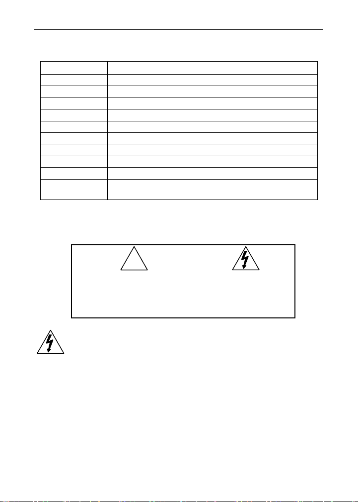
ORDERING INFORMATION
Model Description
DPA1200 Meter Copy Cable, 3' (0.9 m)
DPA1232 RS-232 Serial Adapter
DPA1485 RS-485 Serial Adapter
DPA7485-I RS-232 to RS-422/485 Isolated Converter
DPA7485-N RS-232 to RS-422/485 Non-Isolated Converter
DPA8008 USB Serial Adapter
DPA8232-N USB to RS-232 Non-Isolated Converter
DPA8485-I USB to RS-422/485 Isolated Converter
DPA8485-N USB to RS-422/485 Non-Isolated Converter
DP6000-SOFT
DP6000-SOFT Software for Meters
FREE Download available at www.omega.com
SAFETY INFORMATION
!
CAUTION: Read complete
instructions prior to installation and operation of the
equipment.
WARNING
WARNING: Risk of
electric shock.
Hazardous voltages could exist on serial communication wiring
networks. Installation and service should be performed only by
trained service personnel.
4
Page 5

Serial Communication Converters & Adapters Instruction Manual
Table of Contents
ORDERING INFORMATION --------------------------------------------- 4
SAFETY INFORMATION ------------------------------------------------- 4
SPECIFICATIONS ---------------------------------------------------------- 7
DPA1232 RS-232 Serial Adapter --------------------------------------------- 7
DPA1485 RS-485 Serial Adapter --------------------------------------------- 7
DPA7485 RS-232 to RS-422/485 Converter ------------------------------ 7
DPA8008 USB Serial Adapter ------------------------------------------------- 8
DPA8232 USB to RS-232 Converter ---------------------------------------- 8
DPA8485 USB to RS-422/485 Converter ---------------------------------- 8
SERIAL COMMUNICATIONS OVERVIEW -------------------------- 9
DPA1232 RS-232 SERIAL ADAPTER ------------------------------- 11
Description ----------------------------------------------------------------------- 11
Installation ------------------------------------------------------------------------ 12
Connections -------------------------------------------------------------------- 13
Serial Communication Address (serial) ------------------------------ 13
DPA1485 RS-485 SERIAL ADAPTER ------------------------------- 14
Description ----------------------------------------------------------------------- 14
Installation ------------------------------------------------------------------------ 15
Serial Communication Address (serIAl) ------------------------------ 15
Connections -------------------------------------------------------------------- 18
DPA7485 RS-232 TO RS-422/485 CONVERTER ----------------- 19
Description ----------------------------------------------------------------------- 19
Installation ------------------------------------------------------------------------ 20
Connections -------------------------------------------------------------------- 21
DPA8008 TO USB SERIAL ADAPTER ------------------------------ 22
Description ----------------------------------------------------------------------- 22
Installation ------------------------------------------------------------------------ 22
DPA8232 USB TO RS-232 CONVERTER -------------------------- 23
Description ----------------------------------------------------------------------- 23
DPA8485 USB TO RS-422/485 CONVERTER --------------------- 24
Description ----------------------------------------------------------------------- 24
Installation ------------------------------------------------------------------------ 25
Connections -------------------------------------------------------------------- 26
TROUBLESHOOTING ---------------------------------------------------- 27
5
Page 6

Serial Communication Converters & Adapters Instruction Manual
Table of Figures
Figure 1. General Four-Wire Network Connection .......................... 10
Figure 2. General Two-Wire Network Connection ........................... 10
Figure 3. RS-232 Adapter Connections ............................................ 12
Figure 4. RS-422 or RS-485 Wiring ................................................... 16
Figure 5. RS-485 Two-Wire Multi-Drop Wiring ................................. 17
Figure 6. Connections for DPA1485 to Serial Converter ................. 18
Figure 13. DPA7485 Terminal Connectors and DIP Switch ............ 20
Figure 14. DPA7485 DIP Switch Settings ......................................... 20
Figure 16. Connections for DPA7485 in a Four-Wire Network ....... 21
Figure 17. Connections for DPA7485 in a Two-Wire Network ........ 21
6
Page 7

Serial Communication Converters & Adapters Instruction Manual
SPECIFICATIONS
DPA1232 RS-232 Serial Adapter
COMPATIBILITY EIA-232
CONNECTORS PC compatible 9-pin D subminiature connector (DB9) and
CABLE 6' (1.8 m) standard Cat5e cable provided with adapter
DISTANCE Adapter to meter: 6' (1.8 m) max; Adapter to computer: 50'
POWER Powered by meter M-Link connection
STATUS
INDICATION
DPA1485 RS-485 Serial Adapter
COMPATIBILITY EIA-485
CONNECTORS Removable screw terminal connector and RJ11 (adapter to
CABLE 6' (1.8 m) standard Cat5e cable provided with adapter
DISTANCE Adapter to meter: 6' (1.8 m) max; Adapter to computer:
POWER Powered by meter M-Link connection
STATUS
INDICATION
RJ45 (adapter to meter)
(15 m) max; serial interface cable not provided
Separate LEDs for Power (P), Transmit (TX), and
Receive (RX)
meter)
3,937' (1,200 m) max
Separate LEDs for Power (P), Transmit (TX), and
Receive (RX)
DPA7485 RS-232 to RS-422/485 Converter
COMPATIBILITY EIA-232, EIA-422, and EIA-485
CONNECTORS Screw terminal connector and DB9
DISTANCE RS-232 connection: 50' (15 m) max; RS-422/485 connec-
NUMBER OF
UNITS
POWER 9-12 VDC; 115 VAC/12 VDC adapter included
STATUS
INDICATION
ISOLATION DPA7485-I: 1500 VAC between data lines; 700 VDC
DPA7485-N: 1500 VAC between data lines only
tion: 3,937' (1,200 m) max
Up to 31 RS-485 compatible devices
Separate LEDs for Power (P), Transmit (TX), and
Receive (RX)
input/output-to-power
7
Page 8

Serial Communication Converters & Adapters Instruction Manual
DPA8008 USB Serial Adapter
COMPATIBILITY USB 1.1, USB 2.0
CONNECTORS RJ45, and USB Type B
CABLE One 6' (1.8 m) standard Cat5e cable and one 3.28’ (1.0 m)
DISTANCE Adapter to meter: 6' (1.8 m) max. USB connection: 10' (3
DRIVER Windows 98/SE, ME, 2000, Server 2003/2008, XP 32/64-
POWER USB Port
STATUS
INDICATION
USB A-B Male cable provided with adapter
m) max
Bit, Vista 32/64-Bit, Windows 7 32/64-Bit
Separate LEDs for Power (P), Transmit (TX), and Receive
(RX)
DPA8232 USB to RS-232 Converter
COMPATIBILITY USB 1.1, USB 2.0, EIA-232
CONNECTORS PC compatible 9-pin D subminiature connector (DB9) and
DRIVERS Windows® 98/2000/ME/XP
DISTANCE USB connection: 10' (3 m) max; RS-232 connection: 50'
POWER USB port
USB Type A
(15m) max
DPA8485 USB to RS-422/485 Converter
COMPATIBILITY USB 1.1, USB 2.0, EIA-422, and EIA-485
CONNECTORS Screw terminal connector and USB Type B
DRIVERS Windows® 98/2000/ME/XP, Linux 2.4 & greater
DISTANCE USB connection: 10' (3 m) max; RS-422/485 connection:
NUMBER OF
UNITS
POWER USB port
STATUS
INDICATION
ISOLATION DPA8485-I: 1500 VAC between data lines; 700 VDC
DPA8485-N: 1500 VAC between data lines only
3,937' (1,200 m) max
Up to 31 RS-485 compatible devices
Separate LEDs for Power (P), Transmit (TX), and
Receive (RX)
input/output-to-power
8
Page 9

Serial Communication Converters & Adapters Instruction Manual
SERIAL COMMUNICATIONS OVERVIEW
RS-232, RS-422, and RS-485 are standard interfaces approved by the
Electronic Industries Alliance (EIA) for connecting serial devices. In EIA
terms, the device (e.g. meter) that connects to the interface is called a
Data Communications Equipment (DCE) and the device to which it connects (e.g. the computer) is called a Data Terminal Equipment (DTE).
The RS-422 standard was designed to replace the older RS-232 standard because it supports higher data rates and greater immunity to electrical interference. RS-485 is similar to RS-422 but can support multipoint connections per line because it uses lower-impedance drivers and
receivers.
Line drivers and receivers are used to exchange data between two or
more points (nodes) on a serial communications network. Reliable data
communications can be difficult in the presence of induced noise,
ground level differences, and other hazards associated with installation
of a network. When communicating at high data rates, or over long distances in real world environments, RS-232 is often inadequate. The
differential data transmission of RS-422 and RS-485 offers superior
performance in most applications. Differential signals can help nullify the
effects of ground shifts and induced noise signals that can appear as
common mode voltages on a network.
RS-422 was designed for greater distances and higher baud rates than
RS-232. In its simplest form, a pair of converters from RS-232 to
RS-422 (and back again) can be used to form an "RS-232 extension
cord". Data rates of up to 100 kbits/second and distances of 3,937'
(1,200 m) can be accommodated with RS-422.
RS-422 devices however cannot be used to construct a true multi-point
network. A multi-point network consists of multiple drivers and receivers
connected on a single bus, where any point (node) can transmit and/or
receive data. RS-485 is an enhanced version of the RS-422 standard,
which allows multiple drivers and receivers on the same two-wire or
four-wire system. The RS-485 standard specifies up to 32 drivers and
32 receivers on a single bus, but with the introduction of "automatic"
repeaters and high-impedance drivers/receivers, this number can be
extended to hundreds of points (nodes) on a network.
The cabling used for an RS-422 or RS-485 serial communications
network should always be a high quality cable such as Belden 8162 or
9
Page 10

Serial Communication Converters & Adapters Instruction Manual
Alpha 6203C. A two-wire system requires two twisted pairs, and a fourwire system requires three twisted pairs (the extra twisted pair is
needed for the signal ground).
Figure 1 illustrates how to connect a general four-wire network (a fourwire network actually contains 5 wires).
Figure 1. General Four-Wire Network Connection
Figure 2 illustrates how to connect a general two-wire network (a twowire network actually contains 3 wires). Note that the DPA7485 and
DPA8485 have DIP switches that allow for two-wire connections without
the need to externally wire the DO to the DI and the /DO to the /DI (see
the converter section for complete details).
Figure 2. General Two-Wire Network Connection
10
Page 11

Serial Communication Converters & Adapters Instruction Manual
DPA1232 RS-232 SERIAL ADAPTER
Description
The DPA1232 converts the serial output of the meter to an unbalanced,
full-duplex RS-232 signal.
The RS-232 port has a female DB9 connector with pins 2 (RX output),
3 (TX input), and 5 (Signal Ground). Pins 7 (RTS) and 8 (CTS) are tied
together, and pins 1 (CD), 4 (DTR), and 6 (DSR) are tied together. The
adapter is powered by the meter M-Link connection.
Baud rates are adjustable and handled by the (see the meter Instruction
Manual for more details).
The DPA1232 has three diagnostic LEDs: a Power (P) LED to show
when the adapter is powered properly, a Transmit Data (TX) LED to
show when the adapter is sending data out from the PC side, and a
Receive Data (RX) LED to show when the adapter is receiving data
from the meter.
11
Page 12

Serial Communication Converters & Adapters Instruction Manual
Installation
Figure 3 shows the connection of a meter to a PC using the DPA1232
serial adapter. The DPA1232 has an RJ45 connector to connect the
Cat5e cable and a PC compatible 9-pin D subminiature connector
(DB9). The DB9 can be connected directly to the PC or by using a
standard serial extension cable.
RS-232 Adapter
Serial
Cable
(Not Provided)
Cat5e Cable
(Provided)
Figure 3. RS-232 Adapter Connections
12
Page 13

Serial Communication Converters & Adapters Instruction Manual
Connections
A Cat5e cable is provided to connect the meter to the DPA1232 serial
adapter.
Serial Communication Address (serial)
For the meter, the address may be programmed from 001 to 247. The
meter is factory set to address 001.
To change the meter address:
1. Press and hold the Menu button for three seconds to access Advanced Features menu of the meter.
2. Press Up arrow until Serial (SEriaL) menu is displayed and press
Enter, Addres is displayed.
3. Press Enter to change meter address using Right and Up arrow
buttons. Press Enter to accept.
4. Press Menu button to exit and return to Run Mode.
13
Page 14

Serial Communication Converters & Adapters Instruction Manual
DPA1485 RS-485 SERIAL ADAPTER
Description
The DPA1485 converts the serial output of the meter to balanced, full or
half-duplex RS-485 signals.
The DPA1485 has a removable screw terminal connector for the
RS-485 terminals which includes Transmit Data (DO) and (/DO), Receive Data (DI) and (/DI), and Signal Ground. The adapter is provided
by the meter's M-Link connection.
Baud rates are adjustable and handled by the (see the meter Instruction
Manual for more details).
The DPA1485 has three diagnostic LEDs: a Power (P) LED to show
when the adapter is powered properly, a Transmit Data (TX) LED to
show when the adapter is sending data out from the PC side, and a
Receive Data (RX) LED to show when the adapter is receiving data
from the meter.
14
Page 15

Serial Communication Converters & Adapters Instruction Manual
Installation
Figure 4 shows the connection of a meter to a PC using the DPA1485
serial adapter and a DPA7485 RS-232 to RS-422/485 converter in an
RS-422 network. The DPA1485 has an RJ45 connector to connect the
Cat5e cable and a screw terminal connector to connect to the RS-422
network. Figure 5 shows the connection of several meters with
DPA1485 serial adapters to a PC using a DPA7485 RS-232 to RS422/485 converter in an RS-485 network.
Serial Communication Address (serIAl)
When using more than one meter in a multi-drop or multi-point mode,
each meter must be provided with its own unique address. For the meter the address may be programmed from 001 to 247. The meter is factory set to address 001.
To change the meter address:
1. Press and hold the Menu button for three seconds to access Advanced Features menu of the meter.
2. Press Up arrow until Serial (SEriaL) menu is displayed and press
Enter, Addres is displayed.
3. Press Enter to change meter address using Right and Up arrow
buttons. Press Enter to accept.
4. Press Menu button to exit and return to Run Mode.
15
Page 16

Serial Communication Converters & Adapters Instruction Manual
r
r
r
A
r
RS-232 Serial
Connections
to PC
RS-232 to RS-485
Converte
DO
DO
Shield
DI
DI
R
Twisted-Pai
RS-485
dapte
Cat5e Cable to
Mete
(Provided)
DI DO DO
DI
R
Figure 4. RS-422 or RS-485 Wiring
Notes:
1. Termination resistors are optional and values depend on the cable
length and characteristic impedance. Consult the cable manufacturer
for recommendations.
2. Refer to RS-232 to RS-422/485 Converter documentation for further
details.
3. Use shielded cable, twisted-pairs plus ground. Connect ground shield
only at one location.
16
Page 17

Serial Communication Converters & Adapters Instruction Manual
r
r
r
A
r
RS-232 Serial
Connections
RS-232 to RS-485
Shield
Twisted-Pai
YPPA7485
Converte
DO
DO
to PC
DI
R
DI
dapter #1
DI DO DO
DI
Cat5e Cable to
(Provided)
Mete
YPPA1485
RS-485
Adapte
Last Adapter
DI DO DO
DI
R
Figure 5. RS-485 Two-Wire Multi-Drop Wiring
Notes:
1. Termination resistors are optional and values depend on the cable
length and characteristic impedance. Consult the cable manufacturer
for recommendations.
2. Refer to RS-232 to RS-485 Converter documentation for further de-
tails.
3. Use shielded cable, twisted-pair plus ground. Connect ground shield
only at one location.
17
Page 18

Serial Communication Converters & Adapters Instruction Manual
Connections
A Cat5e cable is provided to connect the meter to the DPA1485 adapter.
Figure 6 details the wiring connections from the DPA1485 to an
RS-422/485 serial converter (such as the DPA7485 or DPA8485) for a
four-wire network.
DPA1485 to RS-422/485 Serial
Converter Connections
RS-422/485
Serial Converter
DO DI
DO DI
DI DO
DI DO
DPA1485
RS-485 Adapter
Figure 6. Connections for DPA1485 to Serial Converter
If the serial converter is configured for a two-wire network then the requirement to externally wire the DO to the DI and the /DO to the /DI on
the DPA1485 screw terminal connector is needed.
18
Page 19

Serial Communication Converters & Adapters Instruction Manual
DPA7485 RS-232 TO RS-422/485 CONVERTER
Description
The DPA7485 converts unbalanced, full-duplex RS-232 signals to balanced, full or half-duplex RS-422 or RS-485 signals.
The RS-232 port, configured as a DTE port, has a female DB9 connector with pins 2 (RX output), 3 (TX input), and 5 (Signal Ground). Pins 7
(RTS) and 8 (CTS) are tied together, and pins 1 (CD), 4 (DTR), and 6
(DSR) are tied together. The RS-485 terminal blocks support Transmit
Data (DO) and (/DO), Receive Data (DI) and (/DI), and Signal Ground.
A separate terminal block supports the power input (+12VDC) and power ground (GND).
Baud rates are automatic and handled by the DPA7485.
The DPA7485 has three diagnostic LEDs: a Power (P) LED to show
when the converter is powered properly, a Transmit Data (TX) LED to
show when the converter is sending data out from the PC side, and a
Receive Data (RX) LED to show when the converter is receiving data
from the network side.
The DIP switch SW1 is located between the screw terminal connectors
and allows for system configurations.
19
Page 20

Serial Communication Converters & Adapters Instruction Manual
Installation
The DIP switch SW1 allows for several different options. Factory settings for the switch are shown in Figure 7.
1234 5
Figure 7. DPA7485 Terminal Connectors and DIP Switch
The TERM switch position adds an internal 120 ohm termination resistor
when ON (up). Termination should be used on both ends of the network
with high data rates and long wiring runs.
To configure a two-wire network set both of the 2 WIRE switch positions
to ON (up). For a four-wire network set both of the 2 WIRE switches to
OFF (down).
When the RS422 switch position is ON (up) it is configured for an
RS-422 network. For RS-485 networks set the RS422 switch to OFF
(down).
The ECHO switch position allows the data being sent from the RS-232
port to be echoed back into the RS-232 port. In most networks, this is
an undesired effect and the ECHO switch would be OFF (down).
DPA7485 DIP Switch Settings
SW1 Switch Position ON Setting Function
1
2
3
4 RS-422 Mode
5 ECHO Mode
Figure 8. DPA7485 DIP Switch Settings
Network Termination Included
(120 ohm)
2-Wire Network Mode Connection
(factory setting)
2-Wire Network Mode Connection
(factory setting)
20
Page 21

Serial Communication Converters & Adapters Instruction Manual
Connections
To power the DPA7485, connect 12 VDC to the +12VDC and ground to
the GND screw terminals from the supplied 115 VAC/12 VDC adapter.
The DPA7485 may be configured for either a four-wire or two-wire network. Figure 9 details the wiring connections from the DPA7485 to an
RS-422/485 serial device in a four-wire network.
DPA7485 to RS-422/485 Serial Device Four-Wire Connections
DPA7485 Serial Converter RS-422/485 Serial Device
DO
DO
DI
DI
DI
DI
DO
DO
Figure 9. Connections for DPA7485 in a Four-Wire Network
Figure 10 details the wiring connections from the DPA7485 to an
RS-422/485 serial device in a two-wire network when the DIP switches on
the DPA7485 have been set to the “2-Wire Mode”.
DPA7485 to RS-422/485 Serial Device Two-Wire Connections
DPA7485 Serial Converter RS-422/485 Serial Device
DO
DATA
DO DATA
Figure 10. Connections for DPA7485 in a Two-Wire Network
The DPA7485 internally connects the /DI to the /DO and the DI to the DO
when the DIP switches are set to “2-Wire Mode”. Either the /DI or /DO
could be used to connect to /DATA and either the DI or DO could be used
to connect to DATA.
Two DPA7485 RS-232 to RS-422/485 Serial Converters could be used
as a serial extender to allow RS-232 serial devices to communicate over
long distances. This would allow an RS-232 device to operate up to
3,937’ (1,200 m).
21
Page 22

Serial Communication Converters & Adapters Instruction Manual
DPA8008 TO USB SERIAL ADAPTER
Description
The DPA8008 to USB Serial Adapter allows for direct connection of a
meter to the USB port of a PC.
Installation
Figure 22 shows the connection of a meter to a PC using a DPA8008 to
USB Serial Adapter.
Figure 22. USB Adapter Connections
22
Page 23

Serial Communication Converters & Adapters Instruction Manual
DPA8232 USB TO RS-232 CONVERTER
Description
The DPA8232 USB to RS-232 Converter allows for direct connection of
a serial device to the USB port of a PC.
23
Page 24

Serial Communication Converters & Adapters Instruction Manual
DPA8485 USB TO RS-422/485 CONVERTER
Description
The DPA8485 converts USB to balanced, full or half-duplex RS-422 or
RS-485 signals.
The DPA8485 has a removable screw terminal connector for the
RS-422/485 terminals which includes Transmit Data (DO) and (/DO),
Receive Data (DI) and (/DI), and Signal Ground.
Baud rates are automatic and handled by the DPA8485.
The DPA8485 has three diagnostic LEDs: a Power (P) LED to show
when the converter is powered properly, a Transmit Data (TX) LED to
show when the converter is sending data out from the PC side, and a
Receive Data (RX) LED to show when the converter is receiving data
from the network side.
The DIP switch SW1 is located inside the case and allows for system
configurations.
24
Page 25

Serial Communication Converters & Adapters Instruction Manual
Installation
The DIP switch SW1 allows for several different options. Factory settings for the switch are shown in Figure 24.
12345
The termination switch position adds an internal 120 ohm termination
resistor when ON (up). Termination should be used on both ends of the
network with high data rates and long wiring runs.
To configure a two-wire network set both of the 2-wire switch positions
to ON (up). For a four-wire network set both of the 2-wire switches to
OFF (down).
When the RS-422 switch position is ON (up) and the RS-485 switch
position is OFF (down) it is configured for an RS-422 network.
RS-422 switch position is OFF (down) and the RS-485 switch position is
ON (up) it is configured for an RS-485 network.
Figure 24. DPA8485 DIP Switch Location
DPA8485 DIP Switch Settings
SW1 Switch Position ON Setting Function
1
2
3
Network Termination Included
(120 ohm)
2-Wire Network Mode Connection
(factory setting)
2-Wire Network Mode Connection
(factory setting)
4 RS-422 Mode
5 RS-485 Mode (factory setting)
Figure 25. DPA8485 DIP Switch Settings
25
When the
Page 26

Serial Communication Converters & Adapters Instruction Manual
Connections
The DPA8485 is powered by the USB port.
The DPA8485 can be configured for either a four-wire or two-wire network. Figure 26 details the wiring connections from the DPA8485 to an
RS-422/485 serial device in a four-wire network.
DPA8485 to RS-422/485 Serial
Device Four-Wire Connections
DPA8485 Serial
Converter
DO DI
DO DI
DI DO
DI DO
RS-422/485 Serial
Device
Figure 26. Connections for DPA8485 in a Four-Wire Network
Figure 27 details the wiring connections from the DPA8485 to an
RS-422/485 serial device in a two-wire network when the DIP switches on
the DPA8485 have been set to the “2-Wire Mode”.
DPA8485 to RS-422/485 Serial
Device Two-Wire Connections
DPA8485 Serial
Converter
DO
DO
RS-422/485 Serial
Device
DATA
DATA
Figure 27. Connections for DPA8485 in a Two-Wire Network
The DPA8485 internally connects the /DI to the /DO and the DI to the DO
when the DIP switches are set to “2-Wire Mode”. Either the /DI or /DO
could be used to connect to /DATA and either the DI or DO could be used
to connect to DATA.
26
Page 27

Serial Communication Converters & Adapters Instruction Manual
TROUBLESHOOTING
Symptom Check/Action
Power LED is off DPA1232 or DPA1485:
Meter not communicating with
MeterView
If only the TX (or DATA IN) data
status LED is flashing when serial
communications attempted
If both data status LEDs (TX and
RX) are off when trying to communicate
Communications slow Increase the baud rate
Random communication errors 1. Increase the TX delay time
Other symptoms not described
above
®
or other programs
1. Check modular cable connection
2. Check power to meter
DPA7485:
1. Check wall plug adapter output
2. Check power connection polarity
DPA8485, or DPA8008:
1. Check USB connections
2. Try different USB port
3. Check USB port with other device
Check:
1. Serial adapter and cable
2. Serial protocol selected
3. Meter address and baud rate
4. MeterView address and baud rate
5. Check DIP switch setting on the
DPA7485 or DPA8485
Check:
1. Serial adapter and cable
2. Serial protocol selected
3. Meter address and baud rate
4. MeterView address and baud rate
5. Check DIP switch setting on the
DPA7485 or DPA8485
Remove all unnecessary cables and
meters. Try getting the system to work
with only one meter (to ease troubleshooting) and then expand the system
one device at a time.
DPA1232 or DPA7485:
1. Check serial cable
2. Connect the DB9 directly to the PC
3. Try a different serial port
2. Decrease the baud rate
Call Technical Support for
assistance.
27
Page 28

M-5195
LIM7232OM_A
07/12
 Loading...