

Page 1
ANGULAR PNEUMATIC
GRIPPERS 180° SERIES
TM
DIRECTCONNECT
wITh SPRING ASSIST
DCT-RE Series
l Highly Configurable Modular Construction,
Exclusive DIRECTCONNECTTM Technology
l Full Jaw Opening (180°) Allows Part to be
Direct Fed into Gripper, Eliminating One
Additional Motion
l Fail Safe Operation-Internal Spring
to Maintain Gripper Force if Gripper
Loses Air Pressure
l Compact Design for Use in Confined Spaces
l Shielding to Repel Chips for Use in
Harsh Environments
l Repeatability ±0.05 mm (0.002") and
Accuracy of ±0.07 mm (0.0028")
l
Up to 5 Million Cycles in Typical Applications
and 10 Million with Maintenance
l Temperature Rating from -35 to 80°C
(-30 to 180°F)
l System Requires 4 to 7 bar (60 to 100 psi)
Dry Filtered (40 Microns or Better)
Air Supply
l Accessory Equipment Required—
4-Way 2-Position Pneumatic Control Valve
Shown
smaller
than
actual
size.
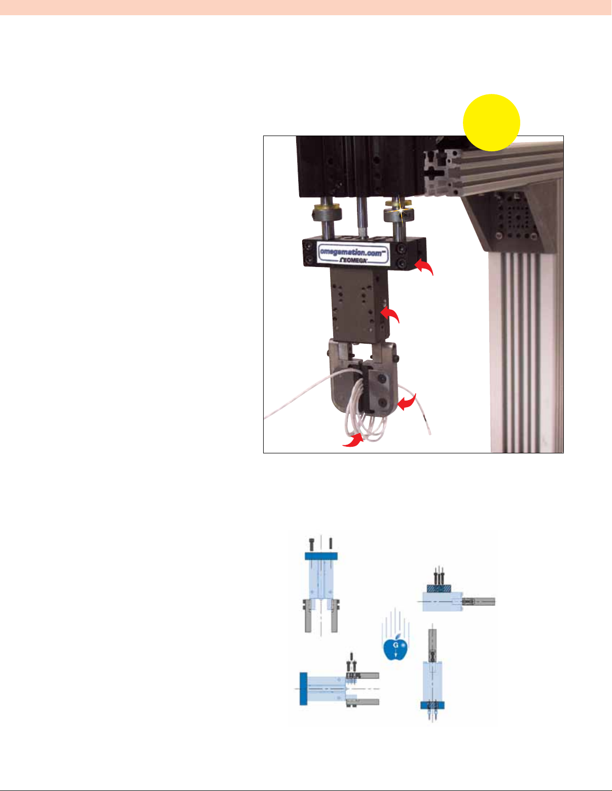
EXTT-3CU-26S
thermistor and
RTD extension wire,
visit omega.com
DLT-10M-E-C-50
linear thruster
slide visit omega.com
DCT-RE-16M
angular gripper
with spring assist
Note: Gripper
fingers shown
for reference only,
tooling is customers
responsibility.
No
Adaptor
Plates
Required
PNEUMATIC SPECIFICATIONS
IMPERIAL METRIC
Pressure Operating Range: 4 to 7 bar
(60 to 100 psi)
Cylinder Type: Double acting
Dynamic Seals: Internally lubricated Buna-N
Valve Required to Operate: 4-way, 2-position
AIR QUALITY REQUIREMENTS
Air Filtration: 40 Micron or better
Air Lubrication: Not necessary*
Air Humidity: Low moisture content (dry)
TEMPERATURE OPERATING RANGE
Buna-N Seals (Standard): -35 to 80°C (-30 to 180°F)
FKM Seals (Optional): -30 to 150°C (-20 to 300°F)
MAINTENANCE SPECIFICATIONS
Expected Life Normal Application:
5 million cycles w/preventative maintenance
10+ million cycles*
Field Repairable: Yes
Seal Repair Kits Available: Yes
* Addition of lubrication will greatly increase service life.
MOUNTING INfORMATION
Grippers Can be Mounted and Operated in Any Orientation
Gripper is located from the
top with 2 dowel pins and
assembled with 2 screws.
Fingers are centered over the
jaws, located with 1 dowel pin
and assembled with 2 screws.
C-31
DIRECTCONNECT mounting pattern:
Gripper is located with 2 dowel
pins and assembled with 4 screws.
Alternative pattern: Gripper is
located with 2 dowel pins and
assembled with 2 screws.
The gripper
is protected
from falling
debris when
it is mounted
and operated
upside down.
Gripper can be
operated utilizing top
manifold air ports.
Page 2
Gripper Attachment
Gripper mounting from
side or bottom
FKM Seals
FKM seals for high temperatures
-30 to 150°C (-20 to 300°F) are optional
Quality Components
Made from aluminum
alloy anodized with
PTFE impregnation.
The gripper’s main
components are made
of heat treated steel.
Inductive Sensor
Mounting Kit
Accessory (SD) in order to
sense jaw position. Comes
with 2 holders for tubular
sensors and 2 adjustable
flags (except size -12).
Magneto Resistive
Sensor Mounting Kit
The gripper comes with adjustable
slots for the 2 magnetic sensors
(to control jaw position)
Accessory (BR) in order to
adjust the opening of jaws,
the gripper to hold onto
Multiple
Air Ports
Side or top air
ports (top ports
require O-ring)
Adjustable Stop
between 0° to 180°
Shielded Plate and
Wiper Covers
Gripper body is shielded
to repel chips and other
particulate from internal
drive mechanism
Fail Safe Spring
Internal spring allows
part with loss of air
pressure
Mounting Patterns
DIRECTCONNECT™
mounting surface on back
of body (sizes 12-25)
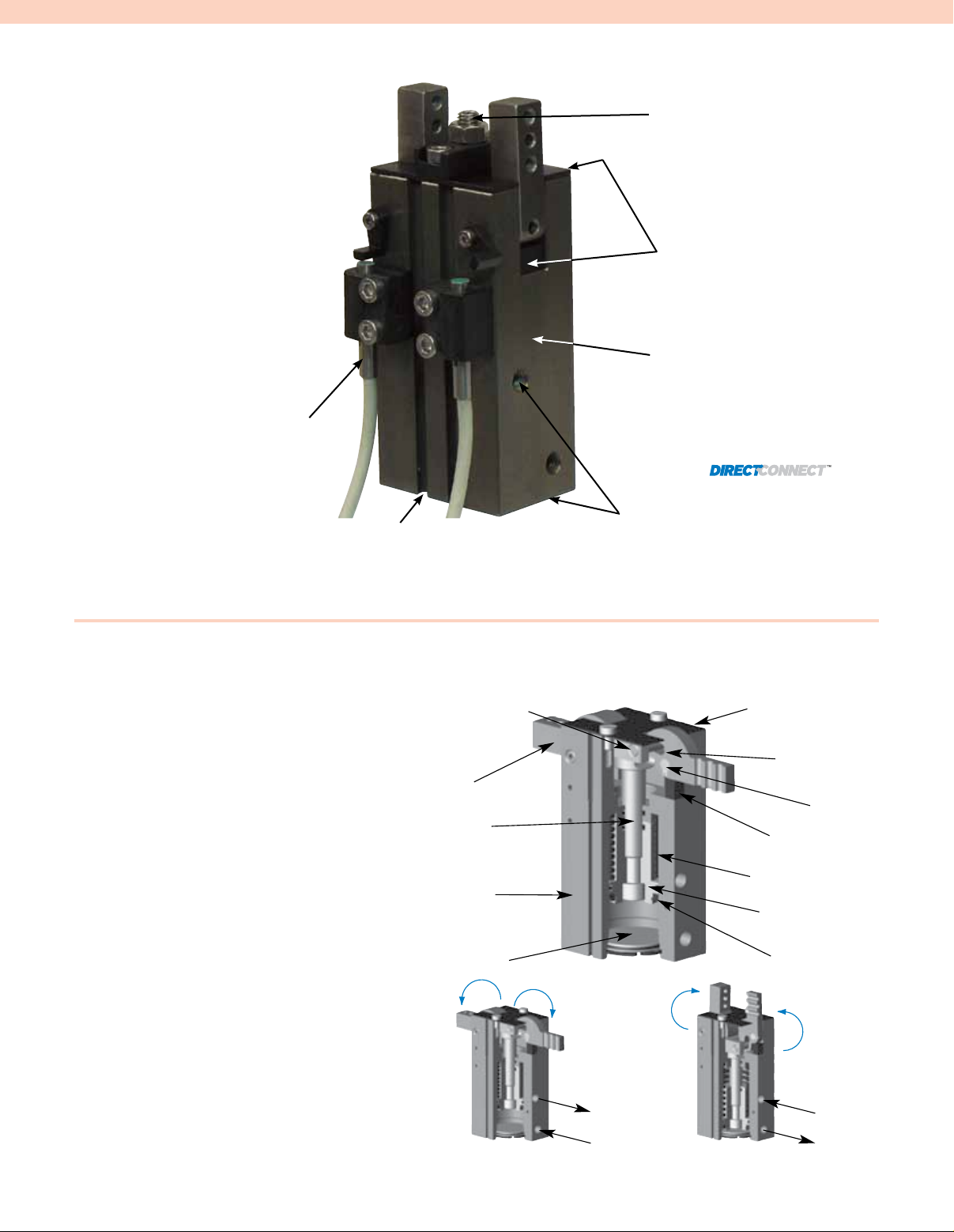
OPERATING PRINCIPLE
l A Double Acting Piston, with a Ring
Magnet for Magneto Resistive Sensing,
is Connected to a Fork Driver on Which
2 Drive Pins are Fixed
l Jaw Rotation is Synchronized with the
Drive Pin-Jaw Assembly
l Sliding in These Slots, Drive Pins Convert
Vertical Motion of the Piston into Rotating
Opposite Synchronous Motion of Both Jaws
l Each Jaw Has a Useful Rotation Stroke of
90°, Between the 90° Open Position and
the 0° Gripping Position, Plus a Gripping
Over-Stroke of Approximately 1.5° Before
Reaching the Fully Gripped Position; Jaws
Have to be Designed for a 0° Gripping
Position (Parallel Jaws)
l The Fail Safe Spring Allow the Gripper
to Retain the Component Should the Air
Supply Fail or for the Gripper to be Used
in Single Acting Mode
Jaw
Driver
Body
Drive Pin
Cap
Exhaust
Pressure
Shielded Plate
Drive Pin Slot
Pivot Pin
Wiper Cover
Fail Safe Spring
Piston
Magnet
Pressure
Exhaust
C-32
Page 3

90°90°
(1.437)
36.5
0.35
9
2Slots to mount
magnetic sensors
(2.028)
51.5
C
L
C
L
(1.18)
30
[M
OPEN
3x5.5DP]
(0.9646)
24.50
CLOSE
(supplied plugged)
x5.5 DP]
Top air port
(supplied plugged)
Top air port
9
(0.35)
20
(0.79)
8.6
(0.339)
x7DP]32x[M
(0.5709)
14.50
[M3
2x[
2.5H9x4.5DP]
C
L
C
L
x6DP]
OPEN
Sideair port
0.0002
1.6
(2.8346)
(0.650)
9
2x[M
-
0.0005-
0.2362
] THRU3
(0.39)
72.00
16.5
(0.31)
8
(0.35)
Side air port
CLOSE
x6DP]
10
(0.063)
(2.52)
64
[6g6]
[
2.5E7] THRU
C
L
Shielded plate
Jaws in
gripping
position
at 0°
C
L
14.50
(0.5709)
3x7DP]
25
(0.9646)
24.50
(0.236)
18
2x[M
80
(3.15)
6.0
(0.98)
35.00
(1.3780)
(0.71)
(0.4921)
12.50
2x[
2.5H7x4.5DP]
4x[M3
2x[
9.5
(0.375)
3H7x6DP]
19.05
(0.7500)
x7DP
]
O-Ring [1x3]
Gripper's
topair port
Our grippers are supplied with
open side air ports and top air
ports plugged. When operating
top air ports, produce manifold
sealing as shown.
[5M
[5M
ø3
(0.12)
ø5
(0.2)
0.8
(0.03)
5
4
3
2
1
0
20
16
12
8
4
0
lbs.
N
EFFECTIVE FINGER LENGTH FROM ROTATION AXIS - L
- ECROF REGNIF 2/F
GRIP FORCE PER FINGER @ 0°
1
25
1.5
35
3 in.
76mm
WARNING!
DO NOT EXCEED
MAXIMUM EFFECTIVE
FINGER LENGTHS
2.0
50
2.5
64
ISP 001 ]rab 7[
ISP 08 ]rab 5.5[
ISP 06 ]rab 1.4[
ISP 04 2[ ]rab 7.
ISP 02 ]rab 3.1[
ISP 0 ]rab 0[
SPECIFICATIONS DCT-12M-RE
Total Rated Grip Force, F @ 7 bar (100 psi)
L = 25 mm (1") @ 0°: 40 N (9 lb)
Stroke: 90° of stroke for each finger
Weight: 0.12 Kg (0.26 lb)
Pressure Range: 4 to 7 bar (60 to 100 psi)
Cylinder Bore Ø: 12 mm (0.472")
Displacement: 1.92 cm3 (0.117 in3)
TEMPERATURE RANGE
Standard Seals: -35 to 80°C (-30 to 180°F)
FKM Seals: -30 to 150°C (-20 to 300°F)
Actuation Open/Close: 0.08/0.05 sec
Accuracy: ±0.07 mm (±0.0028")
Repeatability: ±0.05 mm (±0.002")
Valve Required to Actuate Single Acting:
3-way, 2-position
Valve Required to Actuate Double Acting:
4-way, 2-position
UNLESS OTHERWISE NOTED ALL TOLERANCES ARE AS SHOWN BELOW
Dimensions are
symmetrical about
centerline
LOADING INfORMATION
lbs.
N
16
12
- ECROF REGNIF 2/F
8
4
0
Third Angle
Projection
Metric Threads
Course Pitch
GRIP FORCE PER FINGER @ 0°
4
ISP 001 ]rab 7[
ISP 08 ]rab 5.5[
ISP 06 ]rab 1.4[
ISP 04 ]rab 7.2[
3
2
1
0
1
25
EFFECTIVE FINGER LENGTH FROM ROTATION AXIS - L
1.5
35
WARNING!
DO NOT EXCEED
MAXIMUM EFFECTIVE
FINGER LENGTHS
2.0
50
Imperial inch
0.00 = ±0.0 0.0 = ±0.25
0.000 = ±0.005 0.0 = ±0.13
0.0000 = ±0.0005 0.00 = ±0.013
2.5 in.
65mm
Dimensions: mm (inch)
Notes: DirectconnectTM dimensions are shown in blue.
Jaws have to be designed for a 0° gripping position
(parallel jaws).
Metric mm
Jaws will close 1.5° past parallel. To limit shocks at
the end of an opening or closing stroke, it is highly
recommended to design jaws with minimal inertia
(as light and short as possible).
Flow Controls make it possible to reduce the rotation
LOADING CAPACITY† STATIC DYNAMIC
DCT-12M-RE
Maximum Tensile T 47 N (11 lb) 9.4 N (2 lb)
Maximum Compressive C 47 N (11 lb) 9.4 N (2 lb)
Maximum Moment Mx 1.1 Nm (10 in-lb) 0.3 Nm (3 in-lb)
Maximum Moment My 1.1 Nm (10 in-lb) 0.3 Nm (3 in-lb)
speed and are highly recommended.
Z
L
T
C
Mx
Y
Z
F/2
Maximum Moment Mz 1.1 Nm (10 in-lb) 0.3 Nm (3 in-lb)
†
Capacities are per set of jaws and are not simultaneous.
C-33
Mz
My
F/2
X
Page 4

(0.453)
11.5
17
(1.594)
(0.67)
90°
40.5
90°
(0.35)
9
C
L
C
L
x5.5 DP]
OPEN
CLOSE
(supplied plugged)
x5.5 DP]
Top air port
[M3
[M3
(1.42)
36
(1.1417)
29.00
9
(0.35)
x9DP]42x[M
10
(0.39)
25
(0.98)
Top air port
(supplied plugged)
(0.7087)
18.00
2x[
3H9 x5.5 DP]
C
L
C
L
C
L
x6DP][M
0.3150 -
Side air port
5
(0.31)
20.5
0.0002
2
(0.807)
E7]THRU
[ 2.5
10
79.00
10
] THRU32x[M
-
0.0006
(0.39)
(0.39)
(3.1102)
8
Side air port
CLOSE
x6DP]
OPEN
(0.08)
(2.80)
71
[8g6]
2Slots to mount
magnetic sensors
56.5
(2.224)
(1.516)
38.5
4x[M3x5.5DP]
C
L
Shielded plate
Jaws in
gripping
position
at 0°
C
L
2x[M4x9DP]
18.00
(0.7087)
(3.43)
87
8.0
(0.315)
20
(0.79)
29.00
(1.1417)
(1.043)
26.5
35.00
(1.3780)
(0.5512)
14.00
2x[
3H9 x5.5 DP]
4x[M x7DP]
H7 x6DP]
(0.7500)
19.05
32x[
(0.375)
9.5
3
O-Ring [1x3]
Gripper's
topair port
Our grippers are supplied with
open side air ports and top air
ports plugged. When operating
top air ports, produce manifold
sealing as shown.
[M5
ø3
(0.12)
ø5
(0.2)
0.8
(0.03)
DCT-16M-RE DIRECTCONNECTTM
9
7
4
2
0
40
30
20
10
0
lbs.
N
EFFECTIVE FINGER LENGTH FROM ROTATION AXIS - L
- ECROF REGNIF 2/F
GRIP FORCE PER FINGER @ 0°
1
25
1.25
32
1.75
44
2.25
57
2.5
64
1.5
38
2.75 in.
70mm
WARNING!
DO NOT EXCEED
MAXIMUM EFFECTIVE
FINGER LENGTHS
2.0
51
ISP 001 ]rab 7[
ISP 08 ]rab 5.5[
ISP 06 ]rab 1.4[
ISP 04 ]rab 7.2[
SPECIFICATIONS DCT-16M-RE
Total Rated Grip Force, F @ 7 bar (100 psi)
L = 25 mm (1") @ 0°: 87 N (19 lb)
Stroke: 90° of stroke for each finger
Weight: 0.20 Kg (0.44 lb)
Pressure Range: 4 to 7 bar (60 to 100 psi)
Cylinder Bore Ø: 16 mm (0.630")
Displacement: 4.12 cm3 (0.251 in3)
TEMPERATURE RANGE
Standard Seals: -35 to 80°C (-30 to 180°F)
FKM Seals: -30 to 150°C (-20 to 300°F)
Actuation Open/Close: 0.15/0.12 sec
Accuracy: ±0.07 mm (±0.0028")
Repeatability: ±0.05 mm (±0.002")
Valve Required to Actuate Single Acting:
3-way, 2-position
Valve Required to Actuate Double Acting:
4-way, 2-position
LOADING INfORMATION
- ECROF REGNIF 2/F
Third Angle
Projection
ISP 001 ]rab 7[
ISP 08 ]rab 5.5[
ISP 06 ]rab 1.4[
ISP 04 ]rab 7.2[
Metric Threads
Course Pitch
WARNING!
DO NOT EXCEED
MAXIMUM EFFECTIVE
FINGER LENGTHS
UNLESS OTHERWISE NOTED ALL TOLERANCES ARE AS SHOWN BELOW
Dimensions are
symmetrical about
centerline
lbs.
N
9
40
7
30
4
20
GRIP FORCE PER FINGER @ 0°
10
2
0
0
1
1.25
25
32
EFFECTIVE FINGER LENGTH FROM ROTATION AXIS - L
1.5
38
1.75
44
2.0
51
2.25
57
2.5
64
2.75 in.
70mm
Imperial inch
0.00 = ±0.0 0.0 = ±0.25
0.000 = ±0.005 0.0 = ±0.13
0.0000 = ±0.0005 0.00 = ±0.013
Dimensions: mm (inch)
Metric mm
Notes: Directconnect
Jaws have to be designed for a 0° gripping position
(parallel jaws).
Jaws will close 1.5° past parallel. To limit shocks at
the end of an opening or closing stroke, it is highly
recommended to design jaws with minimal inertia
(as light and short as possible).
dimensions are shown in blue.
TM
Flow Controls make it possible to reduce the rotation
speed and are highly recommended.
F/2
LOADING CAPACITY† STATIC DYNAMIC
DCT-16M-RE
Maximum Tensile T 90 N (20 lb) 18 N (4 lb)
Maximum Compressive C 90 N (20 lb) 18 N (4 lb)
Maximum Moment Mx 2.9 Nm (26 in-lb) 0.7 Nm (6 in-lb)
Maximum Moment My 2.9 Nm (26 in-lb) 0.7 Nm (6 in-lb)
Maximum Moment Mz 2.9 Nm (26 in-lb) 0.7 Nm (6 in-lb)
†
Capacities are per set of jaws and are not simultaneous.
L
C
Z
Y
T
Mx
Z
Mz
X
F/2
My
C-34
Page 5

(0.531)
13.5
22
(0.87)
49.5
47
90°
(1.85)
(1.949)
90°
C
L
C
L
OPEN
(supplied plugged)
CLOSE
(suppliedplugged)
x5.5 DP]
Topair port
[M3x5.5 DP]
[M3
42
(1.65)
(1.3189)
33.50
10
x11DP]52x[M
11
(0.43)
30
(1.18)
Topair port
(0.39)
(0.8465)
21.50
2x[
4H9x8DP]
C
L
Shielded plate
Jaws in
gripping
position
at 0°
C
L
39.00
2x[
4H9x8DP]
21.50
(0.8465)
(4.09)
104
10.0
(0.394)
22
(0.87)
33.50
(1.3189)
(1.30)
33
2x[M5
x11DP]
(1.5354)
(0.78740)
20.00
C
L
C
L
C
L
x6DP][M
0.3937
-
[
Side air port
5
(3.7008)
[M5x6DP]
CLOSE
Side airport
25
(0.31)
8
12
94.00
(0.96)
2.6
3
0.0002
]THRU42x[M
-
0.0006
E7]THRU
(0.43)
(0.47)
11
OPEN
(0.102)
(3.27)
83
[10g6]
2 Slots tomount
magnetic sensors
66.5
(2.618)
(0.35)
9
4x[M3x5.5DP]
19.05
(0.7500)
x6DP]
H7 x6DP]2x[
(0.375)
9.5
3
34x
[M
O-Ring [1x3]
Gripper's
topair port
Our grippers are supplied with
open side air ports and top air
ports plugged. When operating
top air ports, produce manifold
sealing as shown.
ø3
(0.12)
ø5
(0.2)
0.8
(0.03)
DCT-20M-RE DIRECTCONNECTTM
16
13
11
9
7
4
2
0
70
60
50
40
30
20
10
0
lbs.
N
EFFECTIVE FINGER LENGTH FROM ROTATION AXIS - L
- ECROF REGNIF 2/F
GRIP FORCE PER FINGER @ 0°
1.25
32
1.75
44
2.25
57
2.75
70
3.25 in.
83mm
WARNING!
DO NOT EXCEED
MAXIMUM EFFECTIVE
FINGER LENGTHS
ISP 001 ]rab 7[
ISP 08 ]rab 5.5[
ISP 06 ]rab 1.4[
ISP 04 ]rab 7.2[
ISP 02 ]rab 3.1[
ISP 0 ]rab 0[
SPECIFICATIONS DCT-20M-RE
Total Rated Grip Force, F @ 7 bar (100 psi)
L = 25 mm (1") @ 0°: 141 N (32 lb)
Stroke: 90° of stroke for each finger
Weight: 0.33 Kg (0.73 lb)
Pressure Range: 4 to 7 bar (60 to 100 psi)
Cylinder Bore Ø: 20 mm (0.787")
Displacement: 7.92 cm3 (0.483 in3)
TEMPERATURE RANGE
Standard Seals: -35 to 80°C (-30 to 180°F)
FKM Seals: -30 to 150°C (-20 to 300°F)
Actuation Open/Close: 0.20/0.14 sec
Accuracy: ±0.08 mm (±0.003")
Repeatability: ±0.05 mm (±0.002")
Valve Required to Actuate Single Acting:
3-way, 2-position
Valve Required to Actuate Double Acting:
4-way, 2-position
UNLESS OTHERWISE NOTED ALL TOLERANCES ARE AS SHOWN BELOW
Dimensions are
symmetrical about
centerline
LOADING INfORMATION
- ECROF REGNIF 2/F
lbs.
N
13
60
11
50
9
40
7
30
4
20
2
10
0
0
1.25
32
EFFECTIVE FINGER LENGTH FROM ROTATION AXIS - L
Third Angle
Projection
GRIP FORCE PER FINGER @ 0°
ISP 001 ]rab 7[
ISP 08 ]rab 5.5[
ISP 06 ]rab 1.4[
1.75
44
ISP 04 ]rab 7.2[
2.25
57
Metric Threads
Course Pitch
2.75
70
Imperial inch
0.00 = ±0.0 0.0 = ±0.25
0.000 = ±0.005 0.0 = ±0.13
0.0000 = ±0.0005 0.00 = ±0.013
WARNING!
DO NOT EXCEED
MAXIMUM EFFECTIVE
FINGER LENGTHS
3.25 in.
83mm
Dimensions: mm (inch)
Metric mm
Notes: Directconnect
Jaws have to be designed for a 0° gripping position
(parallel jaws).
Jaws will close 1.5° past parallel. To limit shocks at
the end of an opening or closing stroke, it is highly
recommended to design jaws with minimal inertia
(as light and short as possible).
TM
dimensions are shown in blue.
Flow Controls make it possible to reduce the rotation
speed and are highly recommended.
LOADING CAPACITY† STATIC DYNAMIC
DCT-20M-RE
Maximum Tensile T 150 N (34 lb) 30 N (7 lb)
Maximum Compressive C 150 N (34 lb) 30 N (7 lb)
Maximum Moment Mx 6 Nm (53 in-lb) 1.5 Nm (13 in-lb)
Maximum Moment My 6 Nm (53 in-lb) 1.5 Nm (13 in-lb)
Maximum Moment Mz 6 Nm (53 in-lb) 1.5 Nm (13 in-lb)
†
Capacities are per set of jaws and are not simultaneous.
L
Z
C
T
Mx
Y
F/2
Z
Mz
X
F/2
My
C-35
Page 6

20 (0.79)
MAX
6 (0.24)
8 (0.31)
11.7 (0.46)
15 (0.59)
5.5 (0.22)
12.3 (0.48)
35.5 (1.40)
INDUCTIVE SENSORS AND
MOUNTING KIT (SD)
ADJUSTABLE
STOP KIT (BR)
4 (0.16)
60.5 (2.38)
6 (0.24)
Sensors
Ø4 (0.16)
10 (0.39)
M5
ACCESSORIES DIAGRAM
Dimensions: mm (inch)
To Order Visit omega.com/dct-re_series for Pricing and Details
MODEL NO. DESCRIPTION FORCE N (lb)
DCT-12M -RE 180° Series angular gripper with spring assist, 18 mm (0.71") jaw opening 40 (9)
DCT-16M -RE 180° Series angular gripper with spring assist, 20 mm (0.79") jaw opening 87 (19)
DCT-20M -RE 180° Series angular gripper with spring assist, 22 mm (0.87") jaw opening 141 (32)
Note: Sensor and cable sold separately. Inductive sensor not available on DCT-12M-RE.
Ordering Example: DCT-12M-RE, 180° Series pneumatic angular gripper with spring assist,18 mm (0.71") jaw opening and gripper force of
40 N (9 lb). See air fittings for M5 threaded flow control valve, highly recommended due to jaw closing 1.5° past parallel. Suggested
accessories include two PNP magneto resistive sensors with short 90° barrel, OHSP-011 and BR-CT-16, adjustable stop kit. Quick disconnect
sensors will require cable CABL-013, with 5 m (16') length. See accessory table below. DCT-16M-RE, 180° Series pneumatic angular gripper
with spring assist, 20 mm (0.79") jaw opening and gripper force of 87 N (19 lb). See air fittings for M5 threaded flow control valve, highly
recommended due to jaw closing 1.5° past parallel. Suggested accessories include two PNP inductive quick disconnect sensors, OISP-014,
each with two mounting kits, SD-CT-16 and BR-CT-16, adjustable stop kit. Quick disconnect sensors will require cable, CABL-013, with
5 m (16') length each. See accessory table below. CAD file available at omega.com.
ACCESSORIES
MODEL NO. QUANTITY DESCRIPTION
OISP-014 1 or 2 4 mm PNP inductive sensor with quick disconnect
OISN-014 1 or 2 4 mm NPN Inductive sensor with quick disconnect
OHSP-017 1 or 2 PNP magneto resistive sensor long barrel with quick disconnect
OHSN-017 1 or 2 NPN magneto resistive sensor long barrel with quick disconnect
OHSP-011 1 or 2 PNP magneto resistive sensor short 90° barrel with quick disconnect
OHSN-011 1 or 2 NPN magneto resistive sensor short 90° barrel with quick disconnect
CABL-010 1 or 2 Quick disconnect cable 2 m (6.6') in length
CABL-013 1 or 2 Quick disconnect cable 5 m (16') in length
BR-CT-12 1 Adjustment stop kit (1 stop and 1 shielded plate) for DCT-12M-RE
BR-CT-16 1 Adjustment stop kit (1 stop and 1 shielded plate) for DCT-16M-RE
BR-CT-20 1 Adjustment stop kit (1 stop and 1 shielded plate) for DCT-20M-RE
SD-CT-16 1 or 2 Inductive sensor mounting kit for DCT-16M-RE
SD-CT-20 1 or 2 Inductive sensor mounting kit for DCT-20M-RE
C-36
 Loading...