

Page 1

TABLE OF CONTENTS
In Chapter 1
Contents
Features at a Glance
Chapter 1 Introduction & Installation
Features and Configurations
DATAshuttle Model Variations
Installing Your DATAshuttle
Physical Installation
DATAshuttle Operator’s Manual
iii
1 – 4
1 – 6
1 – 8
1 – 9
i
Page 2

DATA
shuttle
In Chapter 2
OPERATOR’S MANUAL
Table of Contents
ii
Contents
Chapter 2 Technical Notes
Using EDITCAL
Auxiliary Analog and Digital Components
Counter/Timer
Use With the AC Development System
Troubleshooting: Installation
Troubleshooting: Operation
Product Specifications
2 – 3
2 – 4
2 – 12
2 – 13
2 – 14
2 – 15
2 – 18
Page 3

DATA
shuttle
OPERATOR’S MANUAL
Table of Contents
iii
Page 4

TABLE OF CONTENTS
Features At A Glance
Highlights of the DATAshuttle
Maximum Resolution
DATAshuttle-16:
DATAshuttle-12:
16 Bits (.0015%)
12 Bits (.024%)
Maximum Speed
DATAshuttle-16:
DATAshuttle-12:
All DATA
8 Differential analog input channels · Dynamic resolution ·
8 Digital I/O lines, user configurable, with provision for
digital isolation modules · Six voltage input ranges, and
Autoranging · Wide acceptance of sensor devices · High
noise rejection integrating converter · Software
linearization for RTDs and Thermocouples · Input protection
to 50 Volts continuous · On-unit counter/timer · Two
optional analog output channels · Parallel passthrough port
for multiple DATAshuttles or printer on same port · Factory
guaranteed accuracy for two years from date of purchase
shuttle
2 kHz
5 kHz
s Feature
DATAshuttle Operator’s Manual
iv
Page 5

DATA
shuttle
OPERATOR’S MANUAL
Table of Contents
v
Page 6

TABLE OF CONTENTS
DATAshuttle Operator’s Manual
vi
Page 7

INTRODUCTION & INSTALLATION
Chapter 1: Introduction &
Installation of the DATAshuttle
General Information
Thank you for selecting the DATA
Our primary objective is to provide you with data acquisition systems that are
easy to install, operate, and maintain. We also strive to furnish the performance you need at the lowest overall cost. The benefits for you are increased
productivity, data you can count on, and, of course, meeting your budget.
We manufacture the DATA
plugs into the parallel port of an IBM, or compatible, desktop or portable computer.
The product’s high noise rejection, input protection to withstand as much as
50 Volts, and guaranteed long term stability make it ideal both for the laboratory and for harsh industrial environments. With its parallel port interface,
built-in terminal panel, and compact, light size, the DATA
pletely portable, providing for a quick and easy set-up in both in-house labs
and remote test sites.
Using the DATA
ware (such as WorkBench PC™ for Windows or DOS, or QuickLog™ PC),
you can easily and very quickly implement a broad spectrum of research and
commercial tasks, in a wide variety of settings. You can, for example,
· Display, and log data
· Measure temperature, pressure, flow
· Capture maximums, minimums, averages, or differences
shuttle
shuttle
together with our graphical interface application soft-
shuttle
for your project!
as an enhancement product that readily
shuttle
is also com-
to disk for later analysis,
and most other analog inputs
from sensors and instruments,
surements,
of mea-
· Monitor and control processes
· Set alarm limits
· Control devices at preset levels
· Control devices from digital input
· Gather data unattended
Y ou can use the system interactively, operating controls or modifying your setup while the system is running.
on any input,
,
(fans, pumps, heaters, etc.),
(from switches or TTL signals), and
.
DATAshuttle Operator’s Manual
1 – 1
Page 8

DATA
DEVELOPMENT
EXPANDABILITY
RANGES/
DATA
shuttle
OPERATOR’S MANUAL
General Information
SYSTEM
People who decide, on the other hand, to write their own software
(rather than using an off-the-shelf application) can employ the
Analog Connection Development System™ hardware driver to
address all features of the unit from within a program they design
and code for their specific purpose.
UNITS OF MEASURE
PRESENTATION
All DA T A
8 digital input/output lines; and you can add one DA T A
shuttle
s have eight differential analog input channels and
shuttle
at a
time to your computer, for as many as 15 units with a total of 120
analog input channels and 120 digital I/Os!
The six input ranges of the DATA
shuttle
span from 50 milliVolts
through 10 Volts DC, making it capable of accepting data from almost any sensor. You can, as well, install a resistor, making the
DATA
shuttle
capable of DC current measurements.
Its high accuracy makes the DATA
shuttle
ideal for precise evalua-
tions in the laboratory or field.
The DA T A
shuttle
together with our software – such as W orkBench
PC for Windows or DOS and QuickLog PC – make it easy to specify engineering units (degrees, volts, milliAmperes, etc.) for measurements, as well as which ranges to use.
(You can measure temperature, for example, by selecting from
among 11 different thermocouple types, or from a wide variety of
resistance temperature devices – RTDs. With the application software, the process simply consists of selecting the type of sensing
device from a menu – the driver itself automatically handles cold
junction compensation and linearization.)
The combination of OMEGA hardware and application software
(WorkBench PC for Windows or DOS or QuickLog PC) enables
both the display of data on the screen, and the logging of data to
disk for later analysis.
Chapter 1 Introduction
1 – 2
The system is capable of showing data on the monitor in a variety
of formats. On-screen meters can provide accurate readings of any
parameter on any channel. Chart displays can indicate trends for
comparison of actual measurements on several channels, or for
setting data points or alarms.
Page 9
INTRODUCTION & INSTALLATION
DYNAMIC
Dynamic Resolution
RESOLUTION
All DATA
shuttle
s incorporate “Dynamic Resolution,” which
improves the unit’s accuracy.
With this feature, resolution is greater at the lower (negative) end
of any range than at the higher end. As your readings approach
the low end of any given range, the resolution becomes finer (that
is, the increments of the signal you can distinguish become
smaller).
Dynamic resolution improvement is most noticeable when the
signal remains below a 10% of full scale threshold (approximately). Our products, consequently, are the best available for
taking accurate measurements of low-level signals, as you would
using a thermocouple sensor.
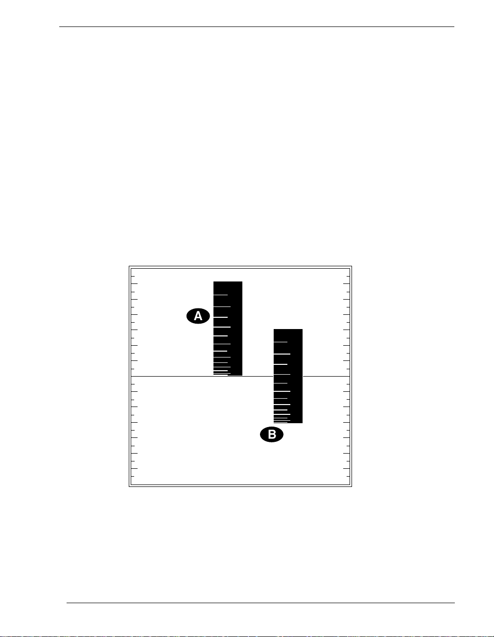
Dynamic resolution is always best toward the negative end of any
range:
Figure 1. Dynamic Resolution for Dissimilar Ranges –
+
10
10
range
5
+
5
–
-5
–
-5
range
-10
Two vertical black “rulers” (range A and range B) portray the impact of
Dynamic Resolution. Their graduations – representing their ability to
resolve – are always finer at the lower (more negative) ends of their
ranges, regardless of the spectrum of values the ranges are measuring.
-10
DATAshuttle Operator’s Manual
1 – 3
Page 10

DATA
ANALOG
RESOLUTION
DATA ACQUISITION
RANGES
NOISE
SENSORS
ACCURACY
INPUT
DIGITAL I/O
COUNTER/TIMER
ANALOG OUTPUT
shuttle
OPERATOR’S MANUAL
Features and Configurations
Features and Configurations
INPUT CHANNELS
SELECTIONS
SPEED
REJECTION
The DA TA
is, .024% of signal), while the DATA
resolution (.0015% of signal). The units possess these features:
Both the DA T A
ential analog input channels.
The resolution of the DATA
the DATA
With the DATA
(These products also feature advanced “dynamic resolution.” See
page 1 – 3 for further explanation.)
The data acquisition rate for the DA TA
5 kHz at 9 bits, in burst mode, while the maximum rate for the
DATA
DATA
ranges, all selectable individually for each analog input channel.
All DATA
noise rejection integrating converter (in “low noise mode” it helps
reject 50/60 Hz AC power line interference).
The DATA
and linearization for thermocouple devices, and signal conditioning for resistance temperature devices (RTDs).
shuttle
-12 is capable of attaining 12 bit resolution (that
shuttle
-12 and the DA T A
shuttle
shuttle
-12, resolution ranges from 9 through 12 bits.
shuttle
-16, it extends from 12 through 16 bits.
shuttle
-16 is 2.0 kHz at 12 bit resolution.
shuttle
-12 and DATA
shuttle
-12 and DATA
shuttle
supports accurate cold junction compensation
shuttle
-16 products have six voltage
shuttle
shuttle
-16 can achieve 16 bit
shuttle
-16 have eight differ -
s is selectable in software. For
shuttle
-12 reaches as high as
-16 models feature a high
PROTECTION
CHANNELS
Chapter 1 Introduction
1 – 4
We guarantee the factory calibration of the DATA
period of two years from the date of purchase. Calibration constants are stored in non-volatile memory on each DATA
Built-in circuitry assures protection of analog input channels for
±50 Volts continuous.
All DATA
the user can configure individually to be input or output.
Every DATA
(for counting pulses or other events) which you can also use as a
pulse output.
All DATA
output channels with one current (4-20mA) and six voltage
ranges, software selectable.
shuttle
s feature eight digital input/output channels that
shuttle
includes a counter/timer for precise timing
shuttle
-AO models feature two optional 12-bit analog
shuttle
for a
shuttle
.
Page 11

INTRODUCTION & INSTALLATION
FOR MORE
SYSTEM
PACKAGE CONTENTS
Features and Configurations
INFORMATION
REQUIREMENTS
For more information about the capabilities of your DATA
shuttle
please see the “Product Specifications” in Chapter 2.
For instructions on controlling the unit with our interface soft-
ware (such as WorkBench PC for DOS or Windows or QuickLog
PC), refer to that particular software manual.
To learn more about data acquisition and process control in general, and how to use the Analog Connection systems together to
accomplish everyday tasks, consult our
Applications
manual.
And, last but not least, if you’re creating your own program to
address the unit for a custom purpose, please see the
nection Development System
Before installing the DA T A
manual
shuttle
.
, make sure the computer system
Analog Con-
fulfills these minimum requirements:
Hardware –
· IBM PC AT (or higher) or -compatible
, with at least 640k
system RAM,
· Floppy disk drive
Software Environment –
· DOS 3.0
(or higher, depending on the application software),
· Application software
and a hard drive.
(WorkBench PC for DOS or Windows,
QuickLog PC, the Analog Connection Development System, or other compatible proprietary software; please see
your software manual for directions for using it with the
DATAshuttle).
,
Your DATA
·
One DATAshuttle
·
One 6V 1A AC Adapter (for U.S. market; may differ for inter-
·
One parallel cable (DB-25 M-F)
·
This manual, including DATAshuttle, QuickLog PC, Applica-
·
One QuickLog PC Disk
·
One AC Development Disk
shuttle
package should include:
national markets)
tions, and AC Development System
DATAshuttle Operator’s Manual
1 – 5
Page 12
DATA
DATA
GP
DATA
RTD
shuttle
OPERATOR’S MANUAL
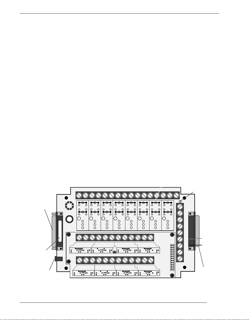
DATAshuttle-GP and DATAshuttle-RTD
DATAshuttle Model Variations
Parallel Input
Connector
Serial Number
& Model Type
5-9V DC In
shuttle
shuttle
The DATA
shuttle
family line offers 3 basic model variations, each
available with either 12- or 16-bit resolution and 2 optional analog outputs, for a total of 12 model types.
The DS-12-8-GP and DS-16-8-GP are general purpose units
-
designed for all types of inputs. The DATA
shuttle
-GP features terminals for 8 differential analog inputs and 8 digital I/O lines, with
room for up to 8 high-power optically isolated modules.
The DS-12-8-RTD and DS-16-8-R TD are specifically designed for
-
high accuracy RTD measurements. The DATA
shuttle
-RTD has signal conditioning set resistors pre-installed at the factory for use
with two or three wire RTDs. This model also features terminals
for 8 digital I/O lines, with room for up to 8 optically isolated
modules.
The DATA
shuttle
-RTD can also measure non-RTD inputs. For
channels that are required to measure other signals, remove the
pre-installed resistors at R3 and R4. See example in the Analog
Auxiliary Components section of Chapter 2 for a more detailed
illustration.
Figure 2. Illustration of the DATAshuttle-GP and DATAshuttle-RTD –
Digital Auxiliary Components &
Dgital Isolation Modules
Out 1 In 1 Out 2 In 2 Out 3 In 3 Out 4 In 4 Out 5 In 5 Out 6 In 6 Out 7 In 7 Out 8 In 8
DIGITAL I/O
R7
R7
R7
R7
R7
R7
R6
R6
R6
R8
R8
+–
CHAN 8 CHAN 7 CHAN 6 CHAN 5
R2
R3/C1 R1
+–
CHAN 1 CHAN 2 CHAN 3 CHAN 4
R2
R3/C1 R1
+–
COM
R
R2
4
R3/C1 R1
+–
COM
R
R2
4
R3/C1 R1
R6
R8
R8
+–
R2
R3/C1 R1
+–
R2
R3/C1 R1
COM
COM
R
U1
4
COM
R
4
R6
R8
COM
R
4
R
4
+–
+–
R6
R8
COM
R2
R3/C1 R1
COM
R2
R3/C1 R1
R7
R6
R8
Analog
Inputs
R
4
Analog
Inputs
R
4
ANALOG
AUXIL
COMPS
ANALOG
AUXIL
COMPS
R7
R6
R8
J1
1 2
23 24
Power Indicator
+5V
CTG
CT
Trig
CT
Out
CT
In
GND
GND
GND
Vref
Light
AO1
(on -AO models)
AO2
Parallel
Passthrough
Chapter 1 Introduction
1 – 6
Page 13
INTRODUCTION & INSTALLATION
DATA
TC
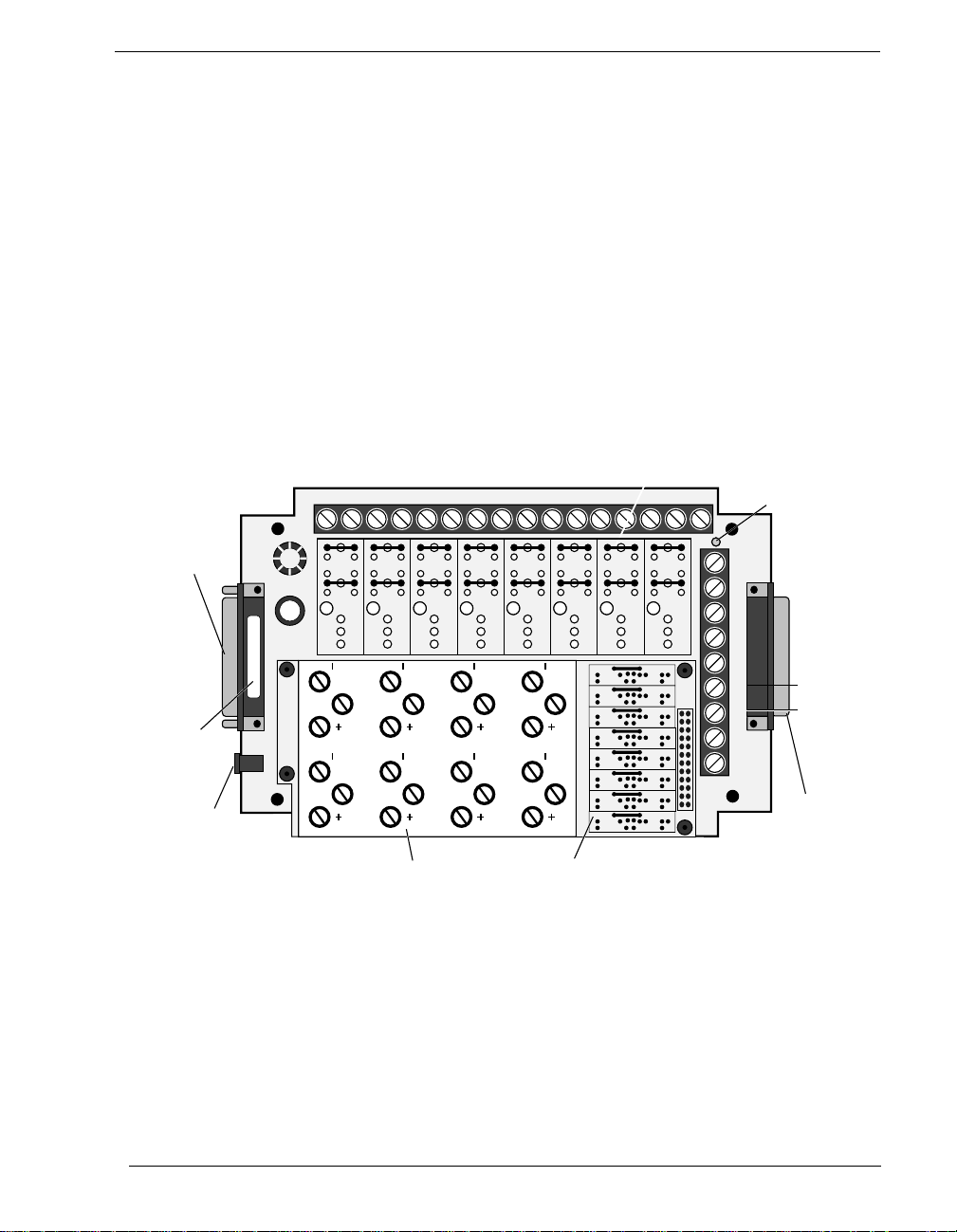
DATAshuttle-TC
shuttle
Parallel Input
Connector
Serial Number
& Model Type
5-9V DC In
The DS-12-8-TC and DS-16-8-TC are the best models for ther-
-
mocouple measurement. The DATA
shuttle
-TC has a large aluminum isothermal plate with screw terminals for 8 analog inputs.
This isothermal plate improves accuracy by attenuating temperature differences at the cold junction connector. Without this
plate, the connectors can vary in temperature by 5˚C or more,
causing a similar error in the reading reported by the DATA
tle
.
The plate, however, does not prevent measurement of other signals, such as voltage or current. In addition, the DATAshuttle-TC
features 8 digital I/O lines, with room for up to 8 optically isolated modules.
Figure 3. Illustration of the DATAshuttle-TC –
Digital Auxiliary Components &
Digital Isolation Modules
Out 1 In 1 Out 2 In 2 Out 3 In 3 Out 4 In 4 Out 5 In 5 Out 6 In 6 Out 7 In 7 Out 8 In 8
DIGITAL I/O
R7
R7
R7
R7
R7
R7
R7
R6
R8
54
ANALOG INPUT
COM COM
R6
R6
R6
R6
R8
R8
R8
6
COM COM
3
COM
7
COM
2
R6
R8
R8
CH
1
R3/C1 R1
CH
2
COM COM
CH
3
CH
4
CH
5
CH
6
CH
7
CH
8
R3/C1 R1
R3/C1 R1
R3/C1 R1
R3/C1 R1
R3/C1 R1
R3/C1 R1
R3/C1 R1
8
1
R7
R6
R6
R8
R8
R
R2
4
AUX
R
R2
R2
R2
R2
R2
R2
R2
COM
4
1 2
R
4
R
4
R
4
R
4
R
4
24
R
4
shut-
Power Indicator
+5V
CTG
CT
Trig
CT
Out
CT
In
GND
GND
GND
Vref
Light
AO1
(on -AO models)
AO2
Parallel
Passthrough
Isothermal Plate
Analog Auxiliary
Components
DATAshuttle Operator’s Manual
1 – 7
Page 14

DATA
shuttle
OPERATOR’S MANUAL
Installation Overview
Installing Your DATAshuttle
Getting your DA TAshuttle up and running is a straightfoward process; you only need to:
· Connect the DATAshuttle to the parallel port of a
computer, and
· Connect power to the DATAshuttle.
Guidelines for loading the software, and for starting up, depend
on the application program you are going to use (such as our
WorkBench PC for DOS or Windows, or QuickLog PC, or a
package by a third party developer who has our authorization).
The program you are going to use with the DATAshuttle might
even be unique and proprietary, a product of your organization.
(The Analog Connection Development System is a powerful set
of utilities making it possible for software engineers to design and
develop their own programs to exploit the DATAshuttle’s many
features).
In any event, please refer to the software provider’s installation
manual, or user guide, for specific information on how to load
and run the particular program.
Troubleshooting –
work, refer to the “Troubleshooting” section in Chapter 2.
If you have any difficulty getting your unit to
Chapter 1 Introduction
1 – 8
Page 15

INTRODUCTION & INSTALLATION
Physical Installation
Installation very simply consists of plugging the DATAshuttle’s
DB-25 cable into the parallel port outside your computer. The
DATAshuttle may be used in combination with any of our data
acquisition products.
Physical Installation
SINGLE UNIT
INSTALLATION
MULTIPLE UNIT
INSTALLATION
To Install a DATAshuttle–
1. TURN THE COMPUTER OFF!
puter’s parallel port without first turning its power switch to
the “off” position.
2. Connect the parallel input connector
DATAshuttle to the parallel port on your computer with the
provided DB-25 cable. The parallel port on the PC has 25
pins and is often labelled “Printer” or “LPT.” Computers may
have up to four parallel ports; the DATAshuttle may be connected to any one of these.
3. Connect the provided AC Adapter
the side of the parallel port of the DATAshuttle. Plug the AC
Adapter into an AC power line.
4. Connect the sensors needed for your application:
cover of the DATAshuttle by removing the four screws in the
corners of the unit. Connect the sensors needed for your
application to the DATAshuttle screw terminals. Replace the
cover. You may wish to refer to the Applications Reference
Manual for examples of particular applications.
To install more than one DATAshuttle–
install the first DATAshuttle. Then for every additional DATAshuttle you wish to install, simply connect the parallel input port of
that DATAshuttle to the passthrough port of the previously
installed DATAshuttle. You may use the additional DB-25 cables
to do this, or you can plug the next DATAshuttle directly into the
previous one. If you prefer to keep the units separate, you may
also connect additional DATAshuttles directly to any or all of the
other parallel ports on your computer.
Never plug anything into the com-
on the left side of the
to the 6-9V DC input just to
Remove the top
Follow the steps above to
In any of these ways, you may connect up to 15 DATAshuttles to
one computer.
DATAshuttle Operator’s Manual
1 – 9
Page 16

DATA
NEXT STEPS
shuttle
OPERATOR’S MANUAL
Physical Installation
Please note, however, that only three DATAshuttles, or only two
DATAshuttle-AO models, may be powered of f the same 6V, 1 amp
AC Adapter. Ther efor e, you must connect a new AC Adapter (see
Step 3 above) to every fourth (or third) DATAshuttle in a series.
Figure 4. Installation with multiple DATAshuttles and printer–
PRINTER
INSTALLATION
KEYBOARD ADAPTER
INSTALLATION
A Note on Board Numbers–
When you are using multiple units in
your installation, each unit needs to have an identity, or “board
number,” for the software to recognize it as “individual.”
When the software is loaded, it will conduct a search for all
installed hardware, scanning first for in-system boards and then
for any DA TAshuttles connected to the parallel ports. Any plug-in
boards that you have installed will be assigned a board number
first. Then the DATAshuttle connected at LPT1 nearest to the
computer will be assigned the next available board number.
Additional DATAshuttles on LPT1 will be assigned sequentially
higher board numbers. This process will be repeated on LPT2,
LPT3, and LPT4 until all units have received a board number.
If you wish to use a printer on the same parallel port as a DATAshuttle–
Connect the printer cable to the passthrough port of the last
DATAshuttle in the series.
For field applications where no AC power line is available–
The Keyboard Adapter power cable (available optionally) may be used
instead of the AC Adapter. To install, simply connect one end of
the cable to the keyboard port on the computer. (This connector
must be the six pin mini DIN style found on IBM PS-2s and most
portable computers.) Plug the other end of the cable into the
DATAshuttle’s DC input jack. Up to three DATAshuttles may be
powered off of one keyboard adapter. (See the “Multiple Unit
Installation” section on page 1 – 9 for instructions on installing
multiple DATAshuttles.)
Chapter 1 Introduction
1 – 10
Installing the Software –
For information on loading and configuring WorkBench PC for DOS or Windows, QuickLog PC, or other
software please refer to the user guide for that software package.
Page 17

DATA
shuttle
OPERATOR’S MANUAL
Chapter 1 Introduction
1 – 11
Page 18

TECHNICAL NOTES
Chapter 2: Technical Notes
Although operations in this chapter are seldom necessary during everyday
data acquisition, you might want to refer to them at certain times during
operation of the DATAshuttle. They are:
· Block diagram (of the DATAshuttle showing on-unit processing);
· Editing calibration numbers to accommodate changes to your installa-
tion, or to restore missing files;
· Auxiliary analog and digital components
· Counter/Timer
· Use with AC Development System software
Overview
· Troubleshooting: some possible problems and solutions after installing,
and during operation of your unit.
· Specifications of the different DATAshuttle models.
DATAshuttle Operator’s Manual
2 – 1
Page 19

DATA
shuttle
Block Diagram
OPERATOR’S MANUAL
Figure 5. Block Diagram of DATAshuttle-12 and DATAshuttle-16 –
Reference
8 Differential
Analog Inputs
Optional Analog
Isolation Modules
on -5B models
User Terminals
8 Digital I/O Lines
Optically Isolated
Modules
4 Counter/Timer Lines
2 Analog Outputs (optional)
Optional Analog
Isolation Modules
on -5B models
Pass Through Parallel
Port to Printer or
Other DATA
shuttles
Voltage
MUX
+5V
Amplifier
Counter/
Gain Control
I/O
Latches
Timer
+15V
-12V
V/F
Converter
Gain
Control
2 12-Bit D/A
Converter
Power
Supply
5-9V
DC IN
**
Digital
*
Processing
Parallel Port
Interface
Parallel
Input
Chapter 2 Technical Notes
2 – 2
*V/F Converter: 12 bits for DATAshuttle-12; 16 bits for DATAshuttle-16
Page 20

CAUTION
STARTING
EDITCAL
EDITCAL
TECHNICAL NOTES
Using EDITCAL
EDITCAL.EXE (or EDITCAL, for short) is our utility program
that allows the modification of calibration numbers.
Changing these numbers will affect the accuracy of the analog
measurements.
Make sure the EDITCAL.EXE program file is in the same subdirectory as the application programs.
Load the EDITCAL.EXE program from the keyboard:
To Start Up EDITCAL.EXE –
1.
At the DOS prompt, enter EDITCAL, then press the [ENTER]
key. (This invokes the utility.)
Using EDITCAL
SELECTIONS
To Select a Function –
1.
Use the arrow keys to navigate back and forth among these
menu selections:
Data Files To merge calibration files supplied from the factory
AC EEPROM To view or modify calibration data on Analog Con-
HS EEPROM To view or modify calibration data on high speed
DS EEPROM T o view/modify calibration DATAshuttle EEPROMs
QUIT Ends this EDITCAL session.
2.
Move the arrow keys until DS EEPROM is flashing.
3.
Press [ENTER].
Continue –
appear after making your selection.
Help –
key to display help about a field that is highlighted.
Proceed according to the on-screen instructions that
At any time during your use of EDITCAL, press the [F1]
into a single file for systems that have multiple units, or
to update existing calibration files.
nection units that have non-volatile on-unit EEPROMS.
units EEPROM, such as WB-WORKMATE or WBFLASH12.
or perform analog recalibration
DATAshuttle Operator’s Manual
2 – 3
Page 21

DATA
AUXILIARY
shuttle
OPERATOR’S MANUAL
Auxiliary Components
COMPONENTS
Auxiliary Analog and Digital
Components
Auxiliary Components are required by some sensors, are used to
protect digital signals, or are used to pull digital outputs to a set
level. There are two areas (one digital and one analog) on the
DATAshuttle for installing auxiliary components. Schematics of
both Analog and Digital auxiliary components are shown in
detail in Figures 6(a) and 6(b) below.
Figure 6. Schematic for Analog & Digital Auxiliary Components –
COM
Screw
Terminal
Screw
Terminal
IN
OUT
+
–
a. Analog Auxiliary Components, each channel
b. Digital Auxiliary Components, each channel
R1
R5
R6
R7
GND (A)
R2
R8
+5V
R4
R3/C1
7404
Board +
Connector
(to main board)
Board –
GND (A)
Vref
+15V
–12V
I/O
GND
Chapter 2 Technical Notes
2 – 4
Each channel on the DATAshuttle has room for its own separate
set of auxiliary components. Examples of their use can be found
in the following pages and in the Applications Reference Manual.
Page 22

ANALOG
AUXILIARY
POWER SUPPLIES
COMPONENTS
TECHNICAL NOTES
Analog Auxiliary Components
Instructions for installing components–
Most common sensors can be connected without the use of auxiliary components. Some of the sensor installations (bridges, RTD
circuits, voltage dividers and current sensors), however, require
auxiliary components. These components can be installed on the
DA TAshuttle for convenience. This requires soldering and some
familiarity with electronics. In the examples in the Applications
Reference Manual, and the following, the component locations are
shown but not the component values; you must calculate the values if they are not supplied with the sensor.
The first step is to remove the daughterboard from the unit, as
you will need full access to it for soldering on the auxiliary components. To do this, simply remove the four screws in the corners
of the daughterboard and lift it off of the DATAshuttle.
When using analog auxiliary components R1, R2, and R5 you
must cut the shorting metal trace that connects the two ends of
the line together before installing any of the components in these
locations. Use a sharp knife to carefully slice through the trace
without cutting additional traces. In the case of R5 this is a plastic
covered metal wire. Diagrams of the auxiliary component area,
hole functions, and connection possibilities are shown on the following page.
A Note on Power Supplies –
The DA TAshuttle supplies the following
voltages to power transducers, strain gauges, etc. The currents
available to the user are limited as follows:
Voltage Tolerance
Maximum Current
(mA)
Output Impedance
(ohms)
Vref(6.9V) ±5% 10 <1
+5V 4.5 to 5.0V 100 <50
+15V ±3% 10 100
-12V ±3% 10 100
Users of the open collector digital outputs and buffer amplifiers
should be careful not to exceed these limits. Any power used
from these supplies will add to the specified supply current used
by the DATAshuttle.
DATAshuttle Operator’s Manual
2 – 5
Page 23

DATA
shuttle
OPERATOR’S MANUAL
Analog Auxiliary Components
Analog Auxiliary Component Area on the DATAshuttle –
– Screw
Board –
Terminal
GND (A)
Ground (A)
Vref
+15V
COM
–12V
– Screw
Terminal
Fig. 7
Fig. 8
Fig. 9
Fig. 10
R5
R2
R3/C1 R1
Board + Board – Board +
R5
R2
R3/C1 R1
R5
R2
R3/C1 R1
R5
R2
R3/C1 R1
R
4
R
4
R
4
R
4
Placement of holes
in auxiliary component
area for a single channel
+ Screw Terminal
Placement of resistors
R1, R2 and R5.
Placement of capacitor
C1 or R3 Resistor for
current measurement.
Placement of R3 may
be to one of five places
on the right side of the
resistor.
Fig. 11
Chapter 2 Technical Notes
2 – 6
R5
R2
R3/C1 R1
R
4
R4 may be in one of
two holes on the right
side to one of 4 holes
on the left.
Page 24

TECHNICAL NOTES
EXAMPLES
Examples: Analog Auxiliary Components
Example 1: Current sense resistor
The DATAshuttle can measure currents up to 50 mA directly. A
24.9 Ohm precision resistor needs to be installed in the auxiliary
component area to do so. This connection for current measurement is shown below. (To see how this connection adds to the
circuit, refer to Figure 6(a).) R3 is used as a shunt resistor across
the positive and negative lines of the channel in use.
To install this resistor, push the resistor ends through the holes
for R3 (from the terminal side) until the resistor lies flat with the
panel surface. On the back side, solder the wires to the holes, and
then clip off the extra wire with pliers. This connection does not
require any additional traces to be cut.
Be sure to select current measurement in the software package
that you are using. This installation allows the measurement of
voltage across the resistor and the conversion of this measurement to current using the equation V=IR. Observe the power rating of the resistor you install at R3. Space is provided for a 1/4
Watt resistor.
Figure 12. Current Measurement Connection –
R5
R2
R1
R
4
DATAshuttle Operator’s Manual
2 – 7
Page 25

DATA
shuttle
OPERATOR’S MANUAL
Examples: Analog Auxiliary Components
Example 2: 3-Wire RTD components
The most popular connection for RTDs is the three wire type.
This sensor requires the installation of resistors R3 and R4. Both
resistors are already installed in the DATAshuttle-RTD model.
Figure 13. 3-Wire RTD Components
RTD
SHIELD
+
COM
–
GND
3-Wire RTD
Vref
R3
R4
+
Analog
Connector
-
However, if you need to install these resistors yourself then do
the following: Figure 10 and Figure 11 show the possible locations of R3 and R4. Figure 7 will show you that R3 and R4 need
to be connected as in Figure 14. R5 is already in place and should
not be removed. To install these resistors push the resistor ends
through the holes for R3 and R4 as shown in Figure 10 (from the
terminal side) until the resistor lies flat with the panel surface. If
two wires cannot fit into the Vref hole then one wire may be soldered to another that is already inserted. On the back side solder
the wires to the holes. Then clip off the extra wire with pliers.
The auxiliary component area in question will now look like Figure 14. This connection does not require any additional traces to
be cut.
Figure 14. 3-Wire RTD Connection –
R5
R
R2
4
R3/C1 R1
Chapter 2 Technical Notes
2 – 8
Page 26

TECHNICAL NOTES
Examples: Analog Auxiliary Components
Example 3: Ground loops
Occasionally there is an installation where the ground connection
is made at the sensor, but it is not reliable. The solution to this
“intermittent” ground is to replace the COM to GND(A) jumper
wire at R5 (Figure 6(a)) with a 10 Megohm, 5%, 1/4 Watt resistor. This provides a ground reference for the analog inputs in
question, but allows very little ground current to flow. In very
noisy environments with intermittent grounds, a smaller resistor
may be used if the readings are erratic.
To install this resistor the wire at R5 must first be removed. After
R5 has been removed push the resistor ends through the holes for
R5 (from the terminal side) until the resistor lies flat with the
panel surface. On the back side, solder the wires to the holes.
Then clip off the extra wire with pliers. The auxiliary component
area in question will now look like Figure 15. This connection
does not require any additional traces to be cut.
Figure 15. Ground Loop Connection
–
R5
R2
R3/C1 R1
R
4
DATAshuttle Operator’s Manual
2 – 9
Page 27

DATA
DIGITAL
CAUTION
shuttle
OPERATOR’S MANUAL
Digital Auxiliary Components
AUXILIARY
COMPONENTS
Installing Digital Modules –
Modules are available to safely connect the digital I/O lines to high
voltage AC and DC sources. There are four basic types:
· AC output: to switch AC power (relay)
· DC output: to switch DC power (relay)
· AC input: to sense AC voltage
· DC input: to sense DC voltage
The output types are used to switch loads on and off. The input
types are used to sense the high/low status of a signal. All of the
modules provide optical isolation between the high voltage and
terminations.
These modules may be installed on any DATAshuttle. You may
have had modules installed at the factory. If not, you may do the
installation yourself. First, remove the jumpers labeled R6 and R7.
This disconnects the digital I/Os from the terminals. The module
will not fit into the panel until these jumpers are removed. Then,
simply insert the module and fasten the retention screw.
Chapter 2 Technical Notes
2 – 10
The terminals for that I/O have now changed their function from
low voltage I/O to high voltage isolated I/O. The two terminals
become one input channel (high and low lines), or one output
channel (like relay contacts), depending on the type of module
you have installed.
When using these terminals as input lines, be sure to connect the
positive line to the old OUT terminal and the negative line to the
old IN terminal. Failure to do this will result in the module not
switching.
Installing Pull-up Resistors –
As noted in the Applications Reference Manual and previously in
this manual, the digital outputs are open collector and must have
a power source connected in order to drive loads. Merely connecting the output terminal through a load (such as a bulb) and then
to digital ground will not work. In this case, a pull-up resistor connecting the output terminal to a power supply will complete the
circuit.
This pull-up resistor is installed in position R8, as shown in Figure
6(b), which connects the output to the unit’ s +5 volt power supply.
Page 28

TECHNICAL NOTES
Digital Auxiliary Components
Figures 2 and 3 in Chapter 1 show the physical location of R8 on
the DATAshuttle. Note that R8 must be installed manually
between the +5 volt supply and the output terminal in question.
To install this resistor, push the resistor ends through the holes
for R8 (from the terminal side) until the resistor lies flat with the
panel surface. On the back side, solder the wires to the holes.
Clip off the extra wire with pliers. This connection does not
require any additional traces to be cut.
Installing Current Limiting Resistors –
To limit the current in the digital input line, install a resistor in
the R6 position (remove the corresponding jumper first).
Install a resistor in the R7 position (after removing the jumper) to
limit the current in the digital output line.
DATAshuttle Operator’s Manual
2 – 11
Page 29

DATA
shuttle
Counter/Timer
OPERATOR’S MANUAL
Counter/Timer
The DATAshuttle features one 16 bit counter/timer that may be
used to count up to 2
16
(65,535) events. The maximum rate of
pulses it can measure is 3MHz. The counter/timer is connected to
an internal 2MHz clock, allowing it 0.5µS resolution.
There are four dedicated terminals for the counter/timer:
Counter/Timers lines available on the DATAshuttle –
Label Name Function
CTG Gate Input/output functions may operate when this
line is high and stop when it is low
CT Trig Trigger Initiate input or output functions on rising
edge
CT Out Output Output pulses or square waves
CT In Input Measure frequency of pulses, count pulses, or
time events
All of these lines are TTL compatible. Please note that they may
not be optically isolated with modules.
For more information and examples about the uses of the
counter/timer please see the Applications Reference or QuickLog
manuals.
Chapter 2 Technical Notes
2 – 12
Page 30

TECHNICAL NOTES
AC Development System
Use With the AC Development System
The DATAshuttle was developed using the framework of our WBAAI/FAI family of plug-in data acquisition boards. As a result, the
DATAshuttle responds to the same commands in our AC Development System software as these boards. Should you wish to use the
AC Development System with the DATAshuttle, you should treat
the DATAshuttle-12 as an WB-FAI and the DATAshuttle-16 as an
WB-AAI. Please note, however, that there are two significant differences between the DATAshuttle and WB-AAI/FAI boards:
1. The DATAshuttle contains its calibration numbers in onboard nonvolatile
RAM
(ACAL, BCAL, DCAL and CCAL) instead of in a calibra-
tion file. CALIB.DAT is not necessary.
2. The DATAshuttle has different minimum sample periods
(set by the J or
j commands) than the WB-AAI/FAI boards. They are as follows:
Minimum sample period for DATAshuttle-12† –
Resolution
Sample Period
(Single Channel)
Sample Period
(Multiple Channels)
9 bits 167 µS 250 µS
10 bits 200 µS 294 µS
11 bits 333 µS 357 µS
12 bits 455µS 500 µS
18 bits * *
†
Minimum sample period for DATAshuttle-16
Resolution
Sample Period
(Single Channel)
(Multiple Channels)
–
Sample Period
12 bits 455 µS 455 µS
13 bits 833 µS 909 µS
14 bits 1,250 µS 1,333 µS
15 bits 2,381 µS 2,500 µS
16 bits 4,545 µS 4,545 µS
18 bits * *
* Low noise mode; 16,667 if power line fre-
quency is 60 Hz; 20,000 if 50 Hz
†
Rates describe a 33MHz IBM 386DX. Minimums
are somewhat lower in faster computers.
DATAshuttle Operator’s Manual
2 – 13
Page 31

DATA
shuttle
OPERATOR’S MANUAL
Troubleshooting: Installation
Troubleshooting: Installation
If you experience difficulty in getting your DATAshuttle up and
running, please check to see that the installation is according to
the descriptions in Chapter 1.
If the software reports a unit failure, or that it cannot find a
DATAshuttle, then try these remedies:
1. Make sure the cable is securely connected
input connector to the parallel port on the computer.
from the DATAshuttle
2. Make sure the DATAshuttle is connected to a power source
AC Adapter or Keyboard Adapter . A r ed light on the board will
indicate that power is present.
3. Verify that the software is up to date
the unit you are using). Contact us, or your software provider.
4. Disconnect additional DATAshuttles
(a version compatible with
and printers in your setup.
, either an
5. Connect the DATAshuttle to another parallel port.
6. Remove any additional data acquisition cards
7. If possible, install the DATAshuttle with another computer
its correct operation.
8. Remove other terminate and stay resident (TSR)
your system’s AUTOEXEC.BAT file, temporarily. Also REM out
any AUTOEXEC.BAT and CONFIG.SYS lines that relate to a
PCMCIA port, such as device drivers, as these have been
known to cause conflicts.
from the computer.
to verify
programs from
9. Make sure that you plug the DATAshuttle in and that power is connected
before starting your computer. Many laptops will deactivate
the parallel port at the start-up if nothing is attached to it.
10. Make sure that the Print Manager is not active in the Windows environment
puters automatically load the Print Manager at startup, and it
can interfere with WorkBench PC for Windows’ ability to communicate with the hardware. Printing is possible while using
the DATAshuttle but not during the initial loading of the WorkBench PC for Windows software.
when attempting to start the DATAshuttle. Some com-
(Please call our Technical Support line before returning a DATAshuttle
– we hope to assist you with your problem via telephone.)
Chapter 2 Technical Notes
2 – 14
Page 32

HINTS
OPERATING
Qs AND As
TECHNICAL NOTES
Troubleshooting: Operation
Troubleshooting: Operation
It’s essential to have exactly one ground reference per channel.
This single connection to ground makes sure you don’t exceed
the common mode range of input.
(More than one connection per channel can lead to ground loops,
causing errors or erratic readings. Connecting the – to the Com
terminal provides a single ground. Your sensor might also provide another ground. If you’re not sure that your sensor is
grounded, try connecting the – to Com, and not, and see which
works best.)
Remember that if speed is not critical, selecting the “low noise
mode” in software always provides the best accuracy and resolution with your data acquisition unit.
Here are mini “case studies” of difficulties, along with some easy
solutions:
Problem: My unit reads analog inputs wrong.
Make sure the calibration numbers in the non-volatile
Action:
memory are non-zero (run EDITCAL to check this). If the
figures are correct, try shorting + to – to Com: the unit
should return a reading around 0V.
Problem: My unit reads the thermocouple as a very negative temperature.
Verify the connections are secure. Opens read as negative
Action:
temperature.
Problem: My readings are noisy.
Try using the low noise mode (see your software manual
Action:
for more information).
Problem: I can’t measure any voltage change with my voltmeter on my
digital output.
Action:
With nothing but a voltmeter connected, this is normal.
The digital outputs are termed “open collector.” These
kind of outputs do not supply any voltage; it must be supplied from another source. This allows the flexibility to
use any supply voltage up to 30V. The easiest way to see
the state of any output terminal is to check the state of the
input terminal with a voltmeter.
DATAshuttle Operator’s Manual
2 – 15
Page 33

DATA
BEFORE CALLING
shuttle
OPERATOR’S MANUAL
Troubleshooting: Operation
Problem: My digital inputs are “high” with nothing connected to them.
This is normal. The digital inputs are pulled up to about
Action:
1.5 volts by leakage from the LS7407 chips. This is
enough to read logic high. You can pull them low with a
470 ohm resistor to ground.
Problem: Can I get any output signal from the digital input terminals?
Yes, you can use an input terminal to drive light loads
Action:
such as a TTL input.
Problem: What should I do with the jumpers connecting the analog input
to COM?
In general, it is best to leave them connected as shipped.
Action:
Problem: My 5V terminal reads only 4.6V.
This is normal. Tolerance is 4.5 to 5V.
Action:
Problem: My analog output accuracy is poor.
From the DOS command line, or in GO.BA T, run GFIND -C.
Action:
This calibrates analog outputs. Note, however, that calibration sends full scale outputs, so it may be necessary to
remove any instruments connected to the outputs.
CUSTOMER SUPPORT
Chapter 2 Technical Notes
2 – 16
Check the following key areas to validate whether or not the DATAshuttle
is operational:
1. Make
sure the AC Adapter is not damaged.
To do this, detach the
adapter from the DATAshuttle, while leaving it plugged in to
the wall outlet. Then measure the voltage between the inside
and outside surfaces of the cylindrical connector. In this noload condition, the voltage should measure approximately 9V.
If this is not the case, it is likely that the AC Adapter will need
to be replaced.
2. Check the power section of the DATAshuttle.
After plugging the AC
Adapter back into the DATAshuttle, check to make sure the
LED is functioning. If the LED is not lighting up, then there is
likely a problem with the power section of the unit. Contact
technical support for further assistance.
3. Check the DATAshuttle’s internal power supply.
To do this, it is necessary to measure four voltage terminals on the unit itself: the
+5V and Vref(6.9V) terminals, found at opposite ends of the
terminal strip next to the passthrough connector, and the
Page 34

IF YOU NEED
CUSTOMER SUPPORT
TECHNICAL NOTES
Troubleshooting: Operation
+15V and the -12V terminals, which can be found on the
raised section of the DATAshuttle called the terminal board.
(Please consult the diagrams on pages 1–6 and 1–7 if you are
unable to locate these terminals.)
If you have been installing resistors or capacitors on the analog
input auxiliary section, then it is necessary to remove the terminal board and re-check the +5V and Vref voltages. If, after
removal, these voltages return to normal, it is likely that there
is a short-to-ground on the terminal board. Check the resistor/
capacitor installations for such a short and reinstall the board.
If removal does not fix the +5 and -12 voltages, then there is a
problem with the DA T Ashuttle’s internal power supply. Contact
technical support for further assistance.
T o help us serve you better, please have the following information ready:
Have the part number of your DATAshuttle ready.
1.
2.
Have the type and version number of the software you’re
using.
3.
Have your computer’s type, model, and the version of the
operating system.
DATAshuttle Operator’s Manual
2 – 17
Page 35

DATA
ACCURACY
shuttle
OPERATOR’S MANUAL
Product Specifications: Accuracy & Resolution
Product Specifications
DATAshuttle-12 ACCURACY & RESOLUTION–
Range
-5 to +50 mV 12 µV 0.08% –
-25 to +25mV 12 µV 0.16% –
-50 to +500mV 120 µV 0.05% 0.2%
-250 to +250 mV 120 µV 0.05% 0.2%
VOLTAGE
-1 to +10 V 2.4 mV 0.05% 0.2%
-5 to +5 V 2.4 mV 0.05% 0.3%
T ypical Resolution
at Full Scale
DATAshuttle-16 ACCURACY & RESOLUTION–
Range
-5 to +50 mV 0.8 µV 0.04% –
-25 to +25mV 0.8 µV 0.08% –
-50 to +500mV 8 µV 0.01% 0.05%
-250 to +250 mV 8 µV 0.01% 0.05%
VOLTAGE
-1 to +10 V 150 µV 0.01% 0.05%
-5 to +5 V 150 µV 0.01% 0.10%
General Conditions –
interface unit, source resistance less than 1k Ohms. Includes linearity, drift, offset, resolution, and calibration error. In this table
12 bit (0.024%) resolution in use for the DATAshuttle-12, while
16 bit is in use for the DATAshuttle-16 (0.0015%).
Typical Resolution
at Full Scale
From 15 to 35 degrees C, ambient at the
Absolute Accuracy, the larger of
% of Range: % of Reading:
Absolute Accuracy, the larger of
% of Range: % of Reading:
Chapter 2 Technical Notes
2 – 18
Page 36

TECHNICAL NOTES
Product Specifications: Thermocouple Accuracy
DATAshuttle-12 THERMOCOUPLE ACCURACY –
Type Range (°C.) Resolution (°C.) Accuracy (°C.)
-210 to -100 0.1 – 0.3 ± 2.3
J
-100 to 0 0.05 ± 1.2
0 to 880 0.05 – 0.2 ± 1
-250 to -75 0.15 – 1.0 ± 8
K
-75 to 1260 0.07 – 0.3 ± 1.4
0 to 900 0.06 – 0.2 ± 1.2
-250 to -70 0.1 – 0.5 ± 4
E
-70 to 100 0.04 ± 1
100 to 680 0.04 – 0.15 ± 0.8
-250 to -50 0.15 – 0.8 ± 6
T
-50 to 10 0.02 – 0.8 ± 1.4
10 to 150 0.06 ± 1.2
150 to 400 0.06 – 0.1 ± 1
-50 to 120 0.4 ± 10
S
120 to 380 0.3 ± 5
380 to 1770 0.2 – 0.6 ± 4
-50 to 250 0.2 – 0.4 ± 10
R
250 to 800 0.2 ± 4
800 to 1770 0.2 – 0.4 ± 3
200 to 300 0.7 – 1 ± 20
B
300 to 500 0.4 – 0.7 ± 13
500 to 1000 0.2 – 0.4 ± 8
1000 to 1820 0.2 – 0.4 ± 4
G
25 to 200 0.2 – 1 ± 15
200 to 2315 0.15 – 0.8 ± 4
D
-20 to 2315 0.2 – 1 ± 4
150 to 2000 0.15 – 0.6 ± 3
C
-20 to 2315 0.15 – 1 ± 4
100 to 1500 0.15 – 0.4 ± 3
N
-200 to -100 0.7 – 1.4 ± 5
-100 to 1300 0.4 – 0.7 ± 3
DATAshuttle Operator’s Manual
2 – 19
Page 37

DATA
shuttle
OPERATOR’S MANUAL
Product Specifications: Thermocouple Accuracy
DATAshuttle
-16
THERMOCOUPLE ACCURACY –
Type Range (°C.) Resolution (°C.) Accuracy (°C.)
-210 to -100 0.02 – 0.04 ± 1.2
J
-100 to 100 0.02 ± 0.7
100 to 880 0.01 ± 0.5
-250 to -150 0.03 – 0.15 ± 4
K
-150 to -50 0.03 ± 1
-50 to 1260 0.02 ± 0.7
-250 to -100 0.08 – 0.01 ± 2
E
-100 to 200 0.01 ± 0.6
200 to 680 0.01 ± 0.4
-250 to -120 0.03 – 0.1 ± 3
T
-120 to -25 0.02 – 0.03 ± 0.9
-25 to 200 0.01 – 0.02 ± 0.7
200 to 400 0.01 ± 0.5
-50 to 50 0.1 – 0.2 ± 5
S
50 to 300 0.1 ± 3
300 to 1770 0.08 ± 2
-50 to 25 0.1 – 0.2 ± 5
R
25 to 200 0.1 ± 3
200 to 1770 0.08 ± 2
200 to 300 0.25 – 0.4 ± 10
B
300 to 500 0.15 – 0.25 ± 6
500 to 1000 0.08 – 0.15 ± 4
1000 to 1820 0.08 ± 2
G
25 to 200 0.08 – 0.3 ± 8
200 to 2315 0.08 ± 2
D
-20 to 2315 0.04 – 0.08 ± 2
300 to 1500 0.04 ± 1.3
C
-20 to 2315 0.04 – 0.08 ± 2
100 to 1500 0.05 ± 1.5
N
-200 to -100 0.05 – 0.1 ± 3
-100 to 1300 0.02 – 0.05 ± 1.5
Chapter 2 Technical Notes
2 – 20
Page 38

TECHNICAL NOTES
Product Specifications: Thermocouple Accuracy
Thermocouple Conditions –
Same as General Conditions. Does not
include the accuracy of the thermocouple itself (cold junction
error must be added in; cold junction compensation with
DATAshuttle-TCs only). Resolution assumes 12 bit resolution in
use for DA TAshuttle-12, 16 bit resolution for DAT Ashuttle-16; it is
approximate as resolution varies with temperature measured.
Thermocouples use the 50 mV range. For inputs below -5 mV
(below approximately -100 degrees C), use the +/-25 mV range.
Cold Junction Compensation Error
– For the best resolution while
using the DATAshuttle-TCs, use the 50 mV range above -5 mV.
Cold Junction Compensation Error (degrees C) at terminal temperature of:
Type 25˚C 15˚ & 35˚C 5˚ & 45˚C
J
K
E
T
S
R
B
G
C
D
N
0 < 0.25 < 0.6
0 < 0.3 < 0.7
0 < 0.3 < 0.8
0 < 0.4 < 1.2
0 < 0.6 < 1.3
0 < 0.4 < 1.6
0 < 1.0 < 2.0
0 < 0.7 < 1.7
0 < 0.5 < 1.2
0 < 0.6 < 1.8
0 < 0.6 < 1.2
Cold junction compensation error is in reference to the temperature of the terminals. For types B and G the above error applies
for measured temperatures above 200 degrees C only. The cold
junction sensor can be recalibrated at any temperature from 0 to
50 degrees to improve the accuracy if it will not be used at 25
degrees.
DATAshuttle Operator’s Manual
2 – 21
Page 39

DATA
shuttle
OPERATOR’S MANUAL
Product Specifications: Thermocouple Accuracy
Cold Junction Temperature Differential:
For the DATAshuttle-TC only, the temperature gradient in the air
adjacent to the cold junction plate is attenuated 15 times when
AWG #22 gage or smaller thermocouple wire is used and the
wires are bundled together for at least one foot from the cold
junction terminals. The error is usually less than 0.1 degree C.
For the DATAshuttle-GPs there is no isothermal plate. The cold
junction compensation error consists of the above table plus the
difference between the terminal temperature and the cold junction
sensor. This dif fer ence can be several degrees. The above table applies only after user calibration of the cold junction.
Chapter 2 Technical Notes
2 – 22
Page 40

TECHNICAL NOTES
Product Specifications: RTD Accuracy
DATAshuttle-12 RTD ACCURACY –
Set Resistor
Ω
RTD
Ω
Range
°C.
Resolution
°C.
10 k 50 -200 to 115 0.02 to 0.1 0.9
20 k 50 -200 to 525 0.04 to 0.2 1.2
20 k 100 -200 to 115 0.02 to 0.1 0.9
50 k 50 -200 to >850 0.1 to 0.5 2.1
50 k 100 -200 to 750 0.05 to 0.2 1.4
50 k 200 -200 to 115 0.02 to 0.1 1.0
100 k 100 -200 to >850 0.1 to 0.5 2.1
100 k 200 -200 to 750 0.05 to 0.2 1.4
100 k 500 -200 to 115 0.02 to 0.1 0.9
200 k 200 -200 to >850 0.1 to 0.5 2.1
200 k 500 -200 to 525 0.04 to 0.2 1.2
200 k 1000 -200 to 115 0.02 to 0.1 0.9
500 k 500 -200 to >850 0.1 to 0.5 2.1
500 k 1000 -200 to 750 0.05 to 0.2 1.4
1000 k 1000 -200 to >850 0.1 to 0.5 2.1
Accuracy
°C.
DATAshuttle Operator’s Manual
2 – 23
Page 41

DATA
shuttle
OPERATOR’S MANUAL
Product Specifications: RTD Accuracy
DATAshuttle-16 RTD ACCURACY –
Set Resistor
Ω
RTD
Ω
Range
°C.
Resolution
°C.
Accuracy
10 k 50 -200 to 115 0.005 0.8
20 k 50 -200 to 525 0.01 0.9
20 k 100 -200 to 115 0.005 0.8
50 k 50 -200 to >850 0.03 1.4
50 k 100 -200 to 750 0.01 1.0
50 k 200 -200 to 115 0.005 0.8
100 k 100 -200 to >850 0.03 1.4
100 k 200 -200 to 750 0.01 1.0
100 k 500 -200 to 115 0.005 0.8
200 k 200 -200 to >850 0.03 1.4
200 k 500 -200 to 525 0.01 0.9
200 k 1000 -200 to 115 0.005 0.8
500 k 500 -200 to >850 0.03 1.4
500 k 1000 -200 to 750 0.01 1.0
1000 k 1000 -200 to >850 0.03 1.4
RTD Conditions –
Same as General Conditions. Does not include
the accuracy of the RTD sensor itself. Includes linearization and
signal conditioning errors.
°C.
Assumes 12 bit resolution in use for the DATAshuttle-12; 16 bit
resolution in use for the DATAshuttle-16.
RTD measurements are on the 0-50 mV range.
Chapter 2 Technical Notes
2 – 24
Page 42

TECHNICAL NOTES
INPUT IMPEDANCE
NOISE REJECTION
COMMON MODE
INPUT PROTECTION
RESOLUTION/
Product Specifications
All analog inputs have an impedance rating of >20ΜΩ
Important: All noise measurements are in low noise mode, with
inputs shorted to COM.
CMRR –
Common Mode Rejection Ratio (CMRR) is >80dB under
these conditions: DC to 100 Hz, common mode input ± 7.0 Volts
channel to ground. This specification applies even when one or
more nonmeasured channels exceeds the operating common
mode range.
RANGE
SCAN RATE
DATAshuttle NOISE REJECTION –
Range Typical Internal Noise (RMS)
50 mV 0.5 µV
± 25 mV 0.5 µV
500 mV 4 µV
± 250 mV 4 µV
10 V 50 µV
± 5 V 50 µV
Operating, channel-to-ground –
Nonoperating –
±50 Volts continuous.
±7 Volts
On analog input channels: 50 Volts continuous; 150 Volts
momentary.
Both resolution and scan rate are selectable in software:
DATAshuttle-12 RESOLUTION AND SCAN RATE* –
Resolution
Scan Rate
(Single Channel)
Scan Rate
†
(Multiple Channels)
low noise mode: 0.024 % 50 / 60 Hz 50 / 60 Hz
12 bits: 0.024 % 2,200 Hz 2,000 Hz
11 bits: 0.05 % 3,000 Hz 2,800 Hz
10 bits: 0.1 % 5,000 Hz 3,400 Hz
9 bits: 0.2 % 6,000 Hz 4,000 Hz
DATAshuttle Operator’s Manual
2 – 25
Page 43

DATA
ANALOG INPUT
DIGITAL
shuttle
OPERATOR’S MANUAL
Product Specifications
DATAshuttle
-16
RESOLUTION AND SCAN RATE* –
Resolution
Scan Rate
(Single Channel)
Scan Rate
†
(Multiple Channels)
low noise mode: 0.0015% 50 / 60 Hz 50 / 60 Hz
16 bits: 0.0015% 220 Hz 220 Hz
15 bits: 0.003 % 420 Hz 400 Hz
14 bits: 0.006 % 800 Hz 750 Hz
13 bits: 0.012 % 1,200 Hz 1,100 Hz
12 bits: 0.024 % 2,200 Hz 1,800 Hz
* Rates describe an IBM PC 386DX running at 33 MHz with a
math coprocessor. Rates are somewhat faster in faster computers. Please also see the discussion of “Dynamic Resolution” on page 1 – 3.
†
Preliminary
Scan Rate –
Scan rate is the rate in Hertz (or, samples per second)
to read data into memory, including the time it takes to switch
channels and ranges.
To calculate the total scan time for all channels, divide the rate by
the number of channels.
(After placing a burst of data into memory, and depending on
your computer and software, the system requires additional processing time before the data are available to you, or before you can
collect more data).
For the analog input terminals on the DATAshuttle –
· Maximum voltage on any terminal: 150 volts.
For the Digital Input/Output termination on the DATAshuttle –
INPUT/OUTPUT
Chapter 2 Technical Notes
2 – 26
· Maximum current on any terminal: 1 Amp.
· Each line is individually selected to be an input or output.
· Inputs are TTL and MOS compatible
· Outputs are high voltage open collector:
Low Level: 50 mA max, < 0.7 volts at 40 mA (sink)
High Level: 30 volts max, <250 µA (source)
· TTL outputs are available at the input terminals when an I/O is
set to an output:
Low Level: < 0.4 volts at 2 mA (sink)
High Level: > 2.4 volts at 100 µA (source)
Page 44

TECHNICAL NOTES
COUNTER/TIMER
ANALOG OUTPUT
GENERAL
Product Specifications
The DATAshuttle has one on-unit 16 bit counter/timer with 2
MHz internal clock. It can count pulses as fast as 3 MHz.
· Low Level: <0.4 volts at 2mA (sink)
· High Level: >2.4 volts at 100 µA (source)
For the analog output terminals on the DATAshuttle-AO –
· Voltage compliance: will drive up to 1K load positive or negative
· Current compliance: 3 to 30V, sinking current only
· Maximum output speed: 2KHz (preliminary)
DATAshuttle-AO RESOLUTION AND ACCURACY –
INFORMATION
Output Range
Nominal
Resolution
Accuracy
0 to 10V 2.4mV ±10mV
0 to 5V 1.2mV ±5mV
0 to 2V 0.48mV ±3mV
±5V 2.4mV ±10mV
±2.5V 1.2mV ±5mV
±1V 0.48mV ±3mV
4 to 20mA 3.9µA ±50µA
General specifications of the DATAshuttle –
· Analog input operating ambient temperature: 0 to 50 degrees
C, 5 to 90% RH, noncondensing
· Input power voltage range: 5.0 to 9.0 VDC
· Maximum input voltage before damage: 10.0VDC
· Supply current consumed with no external loads: <450mA
· Polarity of DC input connector: Outer surface +, inner surface -
DATAshuttle Operator’s Manual
2 – 27
Page 45

DATA
shuttle
OPERATOR’S MANUAL
Chapter 2 Technical Notes
2 – 28
Page 46

TECHNICAL NOTES
DATAshuttle Operator’s Manual
2 – 29
Page 47

INDEX
A – I
A
AC Adapter 1-5, 1-9, 2-14
with multiple DATAshuttles 1-10
Accuracy
in general conditions 2-18
in RTD measurement 2-23 to 2-24
in thermocouple measurement
2-19 to 2-22
Acquisition speed, data iii, 1-4
Analog auxiliary components 2-5 to
2-9
Analog Connection Development
System 1-2, 1-5, 1-8, 2-13
Analog input
maximum current 2-26
maximum voltage 2-26
Analog input channels iii, 1-4, 2-15
Analog output channels iii, 1-4, 2-16,
2-27
Autoranging iii, 1-4
Auxiliary components 2-4 to 2-11
B
Block Diagram of DATAshuttle 2-2
Board Number 1-10
D
Data acquisition speed iii, 1-4
DATAshuttle-GP 1-6
DATAshuttle-TC 1-7, 2-21, 2-22
DATAshuttle-RTD 1-6
DB-25 parallel cable 1-5, 1-9, 2-13
Digital auxiliary components 2-10 to
2-11
Digital input/output channels 1-4, 1-6,
1-7, 2-16, 2-26
Dynamic Resolution iii, 1-3
E
EDITCAL 2-3
EEPROM 2-3
F
G
Ground loops 2-9, 2-15
C
Calibration numbers 2-3, 2-13
Cold junction compensation 1-2, 1-4
error 2-20
Common mode range 2-25
Common Mode Rejection Ratio
(CMRR) 2-24
Counter/timer iii, 1-4, 2-12, 2-27
Current
maximum 2-26
measurement 1-2
sense resistor 2-7
H
Hardware requirements 1-5
Highlights of the DATAshuttle iii
I
Illustration of DATAshuttle-GP/
DATAshuttle-RTD 1-6
Illustration of DATAshuttle-TC 1-7
Input impedance 2-25
Input protection iii, 1-4, 2-25
Installation
of 3-wire RTD 2-8
of a printer with DA TAshuttle 1-10
DATAshuttle Owner’s Manual
Index – 1
Page 48

DATA
I – S
shuttle
OWNER’S MANUAL
of a single DATAshuttle 1-9
of current sense resistor 2-7
of digital module 2-10
of multiple DATAshuttles 1-10
of pull-up resistors 2-10
troubleshooting 2-14
with the keyboard adapter cable
1-10
J
K
Keyboard Adapter power cable 1-10,
2-14
L
Low noise mode 1-4, 2-13, 2-15
M
Maximum
analog input channels (in an
installation) 1-2
current 2-26
DATAshuttles 1-2
digital input channels (in an
installation) 1-2
resolution iii
speed iii
voltage 2-26
Minimum sample periods 2-13
Multiple DATAshuttles
installation of 1-10
N
O
P
Parallel cable (DB-25) 1-5, 1-9, 2-14
Power supplies 2-5
Printer
installation with DATAshuttle(s)
1-10
Pull-up resistors 2-10
Q
QuickLog PC 1-2, 1-5, 1-8
R
Range
input power voltage 1-2, 1-4, 2-26
Resistance Temperature Device (RTD)
iii, 1-2, 1-4, 1-6, 2-5, 2-8
accuracy in measurement of 2-23
to 2-24
Resolution
and scan rate 2-25 to 2-26
dynamic 1-3
maximum iii, 1-4
selection 1-4
S
Sample periods
minimum 2-13
Scan rate 2-25 to 2-26
Software requirements 1-5
System requirements 1-5
Noise rejection 1-4, 2-25
Alphabetical Index of this Volume
Index – 2
Page 49

T
Thermocouple
accuracy of measurements 2-19 to
2-21
cold junction compensation error
2-21
conditions 2-21
innacurate measurement of 2-15
measurement 1-7
types 1-2
Troubleshooting
of installation 2-14
of operation 2-15
U
V
INDEX
T – Z
Voltage 1-4, 2-26
W
WB-AAI/FAI 2-13
WorkBench PC for DOS 1-2, 1-5, 1-8
WorkBench PC for Windows 1-2, 1-5,
1-8, 2-14
X
Y
Z
DATAshuttle Owner’s Manual
Index – 3
 Loading...