

Page 1
omega.com
e-mail: info@omega.com
For latest product manuals:
omegamanual.info
Shop online at
User’s Guide
DaqIO LabVIEW
TM
Support VIs
OMB-471-0903 rev 1.0
Page 2

Servicing North America:
U.S.A.: One Omega Drive, P.O. Box 4047
ISO 9001 Certified Stamford, CT 06907-0047
TEL: (203) 359-1660 FAX: (203) 359-7700
e-mail: info@omega.com
Canada: 976 Bergar
Laval (Quebec) H7L 5A1, Canada
TEL: (514) 856-6928 FAX: (514) 856-6886
e-mail: info@omega.ca
For immediate technical or application assistance:
U.S.A. and Canada: Sales Service: 1-800-826-6342 / 1-800-TC-OMEGA
®
Customer Service: 1-800-622-2378 / 1-800-622-BEST
®
Engineering Service: 1-800-872-9436 / 1-800-USA-WHEN
®
Mexico: En Espan˜ ol: (001) 203-359-7803 e-mail: espanol@omega.com
FAX: (001) 203-359-7807 info@omega.com.mx
Servicing Europe:
Benelux: Postbus 8034, 1180 LA Amstelveen, The Netherlands
TEL: +31 (0)20 3472121 FAX: +31 (0)20 6434643
Toll Free in Benelux: 0800 0993344
e-mail: sales@omegaeng.nl
Czech Republic: Frystatska 184, 733 01 Karviná, Czech Republic
TEL: +420 (0)59 6311899 FAX: +420 (0)59 6311114
Toll Free: 0800-1-66342 e-mail: info@omegashop.cz
France: 11, rue Jacques Cartier, 78280 Guyancourt, France
TEL: +33 (0)1 61 37 2900 FAX: +33 (0)1 30 57 5427
Toll Free in France: 0800 466 342
e-mail: sales@omega.fr
Germany/Austria: Daimlerstrasse 26, D-75392 Deckenpfronn, Germany
TEL: +49 (0)7056 9398-0 FAX: +49 (0)7056 9398-29
Toll Free in Germany: 0800 639 7678
e-mail: info@omega.de
United Kingdom: One Omega Drive, River Bend Technology Centre
ISO 9002 Certified Northbank, Irlam, Manchester
M44 5BD United Kingdom
TEL: +44 (0)161 777 6611 FAX: +44 (0)161 777 6622
Toll Free in United Kingdom: 0800-488-488
e-mail: sales@omega.co.uk
OMEGAnet®Online Service Internet e-mail
omega.com info@omega.com
It is the policy of OMEGA Engineering, Inc. to comply with all worldwide safety and EMC/EMI
regulations that apply. OMEGA is constantly pursuing certification of its products to the European New
Approach Directives. OMEGA will add the CE mark to every appropriate device upon certification.
The information contained in this document is believed to be correct, but OMEGA accepts no liability for any
errors it contains, and reserves the right to alter specifications without notice.
WARNING: These products are not designed for use in, and should not be used for, human applications.
Page 3

Contents
1. Initial Setup …… 5
2. Using the “How to” Examples …… 6
3. Connector Layout and Naming Convention ……7
4. How to Modify a VI …… 9
5. How to Start a VI from Scratch …… 11
6. How to Run Multiple Acquisitions …… 12
7. DaqIO LabVIEW Palette Layout …… 12
The DaqIO LabVIEW support VIs require LabVIEW 7.0 or greater.
DaqIO LabVIEW Support VIs User’s Guide 877894 3
Page 4

This page is intentionally blank.
4 877894 DaqIO LabVIEW Support VIs User’s Guide
Page 5

Initial Setup
Install Software
Place the Data Acquisition CD into the CD-ROM drive. Wait for PC to auto-run the CD. This
may take a few moments, depending on your PC. If the CD does not auto-run, use the Desktop’s
Start/Run/Browse feature and run the Setup.exe file. After the intro-screen appears, follow the
screen prompts.
After selecting the hardware type, select Enhanced LabVIEW Support from the list of available
software. The Default location is C:\Program Files\DaqIO LabView Support
Setup Hardware
Consult the manual for your specific device for hardware setup and configuration information.
Note: Remember the name you assign to your device as it will be needed in a later step.
Add a DaqIO Pallet to an Existing Palette
1) Open a new blank LabView.vi
2) From the Tools menu item select: Advanced >> Edit palette views
3) In the “Edit Controls and Functions Palettes” dialog box select: “New Setup…”
This is selected from the Palette view list box.
4) Enter a name for the New Palette View
5) Right mouse-click in an open space in the function palette; then select: insert >> submenu.
6) From the “Insert Submenu” dialog select: “Link to a directory”
7) Browse to and open the “C:\Program Files\DaqIO LabView Support” directory.
8) Click the “Select Curr Dir” button. The DaqIO submenu should appear in the function palette.
9) In the “Edit Controls and Functions Palettes” dialog box, click “Save Changes.”
Setting the Paths
In order to use the DaqIO LabVIEW support VI’s from any directory on your machine, the path to
the DaqIO VI’s must be set. This is done as follows:
1) From the Tools menu Item select “Options”
2) In the Options Dialog box select “Paths.”
3) In the second dropdown select “VI Search Path.” Note that the Library Directory is the typical
default displayed.
4) In the test box above the “Insert After” Button, enter:
C:\Program Files\DaqIO LabVIEW Support\*
5) Finish by clicking the “OK” button.
DaqIO LabVIEW Support VIs User’s Guide 877894 5
Page 6

Using the “How to” Examples
Examples for specific devices are located, by default, at:
C:\Program Files\DaqIO LabView Support\Howto and Example VI's
The directory has 4 sub-directories:
Daq Device Examples - For use with Daq Series Devices
DBK Examples - For use with DBK Expansion Cards
Wave Device Examples - For use with WaveBook Series Devices
WBK Examples - For use with WBK expansion modules
The directory also includes a How To with two sub-directories: Daq Devices and Wave
Devices. These sub-directories contain examples of how to perform specific operations
using the DaqIO VI's. Information is provided regarding digital and analog triggering,
waveform output, and asynchronous digital IO along with other operations [that are
included within the directory].
The Howto VI’s contain documented diagrams that explain functions and VI connections
specific to each VI. Howto number 1 and number 2 show the basic steps and most
common wiring connections needed for most VI’s. You should become familiar with
these two VI’s before proceeding with the creation of your own programs.
The Howto VI’s contain generic device configuration VI’s. If you use a Howto VI as a
basis for your own VI, then the generic Howto channel configuration VI’s should be
replaced with channel configuration VI’s that are specific to your device type. This is
necessary to access the full functionality of your device (see following figure).
Replacing a Generic “DAQ Howto” Analog Input VI with a Device Specific VI
6 877894 DaqIO LabVIEW Support VIs User’s Guide
Page 7

Connector Layout and Naming Conventions
Standard Connections
Certain connections are common to the majority of VIs. These “standard connections”
include:
Acquisition Number
Device Name
Error In and Out
Standard Connections
Acquisition Number: This connection exists as an input and output on nearly all VIs. It
is used to keep all the parts of an individual acquisition grouped together. Multip le
acquisitions are, in general, only used when you have multiple main devices running at
different acquisition rates triggered to scan at the same time. See Howto #11 for an
example of multiple acquisitions.
Device Name: This connection is used to tie different sections of a device to its
functions. There are certain VIs that have the Device Name and Device Name Out
connections available, although they are not utilized within the VI itself. The purpose of
these ‘pass through’ connections is to make wiring easier and keep the VI diagram clean
looking.
Error In and Out: Error In and Out connections are utilized to keep certain code from
executing, or to force the execution of code under certain circumstances. To avoid hard
failures and un-initialized configuration problems, it is highly recommended that the
Error In and Error Out ALWAYS be connected between applicable VIs.
DaqIO LabVIEW Support VIs User’s Guide 877894 7
Page 8

Using Channel Names and Trigger Channel Names
Once configured, device channels are referred to by name. All device-configuration VIs
contain string controls that allow you to enter a name for any given channel. If you choose
not to enter a name a default name will be generated. The channel names are used by various
VIs for functions, e.g., Digital Output, and Triggering.
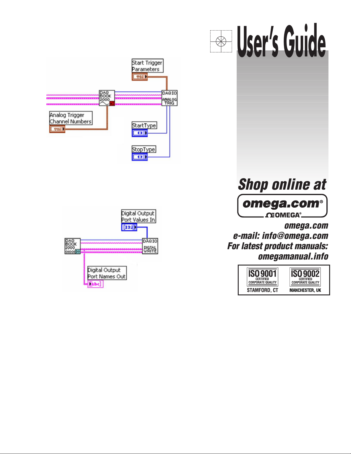
Where applicable, you can select channel numbers to be used as trigger channels. When you
select channels for triggering, the names of the associated channels are then available from
the ‘Trigger Channel Names’ output connection. This connection can be wired directly into
one of the triggering VIs.
Using Trigger Channel Names
Channel Names for Asynchronous and Other Operations
In the case of digital VIs the list of configured channel names is available at the “Channel
Names Out” connection of the digital VIs. This string array can be wired to the “Digital
Output Port Names” connection on the DaqIO Digital Asynchronous Write VI to facilitate
writing data to the configured channels.
Using a Channel Name as an Input to the Digital Write VI
Channel Names can be used to start and stop timers, counters and analog outputs.
8 877894 DaqIO LabVIEW Support VIs User’s Guide
Page 9

How to Modify a VI
All Channel configuration VI’s are similar in connector layout with inputs and outputs for Acquisition#,
Device Name, and Errors. Inserting expansion VI’s is simply a matter of cutting the existing common
connections, making room for the new sub VI, inserting the sub VI, and making new connections and
controls for the sub VI.
Adding a Device
In this illustrated example we will be adding a DBK80 to the Howto #1
diagram (right-hand figure).
1) Delete existing connections (see figure).
2) Make space. After deleting the wires (connections):
(a) Place the mouse cursor between the DaqBook VI (DAQBOOK2000) and the basic trigger VI
(DAQIO BASIC TRIG).
(b) Press and hold the “Control Key,” and at the same time click and hold down the left mouse
button. Next move the mouse an inch or so to the left.
Releasing the mouse button and control key will cause all items in the diagram to shift to the left
the same distance you moved the mouse.
3) Add a DBK Channel Configuration VI to the Diagram.
(a) Select the DaqIO Data Acquisition sub-menu from the Functions palette.
(b) Navigate through the sub-menus as follows:
>> DaqDevice and DBK Configuration >> DBK Expansion >> Analog Input >> DBK80
(c) Select the DBK80 Channel Configuration VI and place it on the diagram.
4) Make Connections to the VI.
For Acquisition Number, Device Name and Error In and Out, make connections on
both sides of the DBK80 Configuration VI.
5) Create the Control.
To complete adding the expansion (DBK80), right-click on the DBK80
Channels connection and select “Create Control.”
DaqIO LabVIEW Support VIs User’s Guide 877894 9
Page 10

Adding Device Sections
Adding Digital channels to the VI diagram follows the preceding steps with the exception
of where the Digital IO channel configuration VI is located. For Example if you wished
to add Digital Inputs to the preceding diagram you would:
(a) Delete the existing wires either to the left or right of
the DBK80.
(b) Make space available to insert the Digital IO
configuration VI.
(c) Browse to the Digital Input Configuration VI
[specific to your device].
(d) Insert the new VI into the diagram.
(e) Connect the wires.
(f) Create the Digital Control.
Adding a Second Device
Adding a second device to a VI is very similar
to adding a device section or DBK expansion.
However, note that device names must be
unique.
Using Device Names on Subsequent VI’s with Multiple Devices
When multiple devices exist, the device name parameter is passed to DBK expansion and
device section VI’s to determine how the connections inter-relate and which main device
is to be utilized in the case of more advanced triggering.
10 877894 DaqIO LabVIEW Support VIs User’s Guide
Page 11

How to Start a VI from Scratch
With the exception of channel and device configuration VI’s, mandatory VI’s can be found under
Acquisition Setup and Control >> Acquisition Control Palette. The Howto #1 Simple Acquisition,
shows the minimum requirements for an acquisition [using DaqIO LabVIEW support VI’s].
Required VI’s for all VI’s for initialization and closure:
COMM INIT: Initializes the DaqIO LabVIEW support (Must be first)
COMM CLOSE: Closes the DaqIO LabVIEW support and releases any resources utilized
(Must be last)
Required VI’s for synchronous operation:
SCAN CONFIG: Sets Scan rate and other scan specific parameters
ACQ ARM: Depending on the trigger method can either immediately start a scan or wait
for a specific trigger condition to occur.
READ SCAN: Once the acquisition has commenced this will retrieve specified amount of
data from the acquisition buffer.
VI’s for Asynchronous operations:
With the exception of Digital IO, asynchronous operations will have
and associated start and stop VI’s. The start, stop and update VI’s
are universal for all configured voltage output channels. This is true,
regardless of device type.
Digital IO VI’s will have only read and write VI’s.
Each of these VI’s has a “Channel Names” connection that must be
wired to determine what channels the operation will be performed
on.
Trigger VI’s:
A method of triggering the acquisition must be provided within your VI. The VI’s are
separated into three groups simple, analog, and digital.
SIMPLE: Generally immediate trigger or TTL trigger starts with manual or scan count
based stops.
ANALOG: Uses individual analog channel voltages or values to start or stop and
acquisition.
DIGITAL: Uses the value of a digital port to start or stop an acquisition.
Advanced triggering can be accomplished by combining the above VI’s. See the various
triggering examples in the “Howto” example section for details.
DaqIO LabVIEW Support VIs User’s Guide 877894 11
Page 12

How to Run Multiple Acquisitions
If you desire to run multiple devices at different rates, or trigger the devices independent of each
other, then you must use a multiple acquisition VI layout. Howto #11 Multiple Acquisition
provides details. In the Howto example, an “Acquisition Stop” VI is used to allow the other
acquisition to continue running in the event that one acquisition stops. When both acquisitions
have completed “Acquisition Close” is called to release all resources.
DaqIO LabVIEW Palette Layout
| -- Acquisition Setup and Control VI's
| -- Acquisition Control
These VI’s perform initialization and control functions for DaqIO LabVIEW
support, Asynchronous operations such as digital port read and write, voltage
output adjustment, and timer adjustment VI’s can be found in this palette
| -- Advanced
Advanced level VI’s should not be altered without an understanding of DaqCOM
| -- Triggering
This palette contains simples and more advanced triggering VI’s
| -- Daq Device and DBK Configuration VI's
| -- Daq Device VI's
This palette contains the base channel configuration VI’s for the Daq series
devices. Select the appropriate sub palette for the device type that you have.
| -- DBK Configuration VI's
This palette contains the channel configuration VI’s for DBK series expansion
devices. It is separated by the type of DBK device.
12 877894 DaqIO LabVIEW Support VIs User’s Guide
Page 13

| -- Howto and Example VI's
| -- Daq Device Examples
This palette contains example VI’s for Daq series devices.
| -- DBK Examples
This palette contains example VI’s for DBK expansion devices.
| -- Howto VI's
The Howto palette contains operation specific example VI’s. Triggering,
reconfiguration, and asynchronous operations and other advanced examples are
located in this palette. Select the appropriate sub palette for the device type that
you have.
| -- PDQ Examples
This palette contains examples describing the utilization of an OMB-PDQ30
for use with an OMB-DAQBOARD-3000 or OMB-DAQ-3000 Series device.
| -- Wave Device Examples
This palette contains the base channel configuration VI’s for the Daq series
devices. Select the appropriate sub palette for the device type that you have.
| -- WBK Examples
This palette contains the channel configuration VI’s for WBK series expansion
devices. It is separated by the type of WBK device.
| -- Utility VI's
This palette contains VI’s used to display channel information, read and write
data files and separate analog and digital data types. See the associated Howto
sections for the utilization of these VI’s.
| -- Wave Device and WBK Configuration VI's
| -- Wave Device VI's
This palette contains the base channel configuration VI’s for the Wave series
devices. Select the appropriate sub-palette for the device type that you have.
| -- WBK Configuration VI's
This palette contains the channel configuration VI’s for DBK series expansion
devices. It is separated by the type of DBK device.
DaqIO LabVIEW Support VIs User’s Guide 986993 13
Page 14

This page is intentionally blank.
14 986993 DaqIO LabVIEW Support VIs User’s Guide
Page 15

WARRANTY/DISCLAIMER
OMEGA ENGINEERING, INC. warrants this unit to be free of defects in materials and workmanship for a
period of 13 months from date of purchase. OMEGA’s WARRANTY adds an additional one (1) mont
grace period to the normal one (1) year product warrant
ensures that OMEGA’s customers receive maximum coverage on each product.
If the unit malfunctions, it must be returned to the factory for evaluation. OMEGA’s Customer Service
Department will issue an Authorized Return (AR) number immediately upon phone or written request
Upon examination by OMEGA, if the unit is found to be defective, it will be
charge. OMEGA’s
including but not limited to
improper repair, or unauthorized modification. This
having been tampered with or shows evidence of having been damaged as a
or current, heat, moisture or vibration; improper specification; misapplication; misuse or other operatin
conditions outside of OMEGA’s control. Components in which wear is not warranted,
limited to contact points, fuses, and triacs.
OMEGA is pleased to offer suggestions on
OMEGA neither assumes responsibility for any omissions or errors nor assumes liability for any
damages that
OMEGA, either verbal or written. OMEGA warrants only that the parts
company
REPRESENT
TITLE, AND ALL IMPLIED
AND FITNESS FOR A PARTICULAR PURPOSE ARE HEREBY DISCLAIMED. LIMIT
LIABILITY: The remedies of purchaser set forth herein are exclusive, and the total liability of
OMEGA with respect to this order, whether based on contract,
indemnification, strict liability or otherwise, shall not exceed the purchase price of the
co mponent upon which liabil ity is base d. In no event shall OMEGA be liable for
consequential, incidental or special damages.
CONDITIONS:
Component” under 10 CFR 21
applications or used on humans. Should any Product(s) be used in or with any nuclear installation or
activity, medical application, used on humans, or misused in any way, OMEGA assumes no
as set forth in our basic
OMEGA and hold OMEGA harmless from any liability or damage whatsoever arising out of
Product(s) in such a manner
will be as specified and free of defects. OMEGA MAKES NO OTHER WARRANTIES OR
ATIONS OF ANY KIND WHATSOEVER, EXPRESSED OR IMPLIED, EXCEPT THAT OF
WARRANTY does not apply to defects resulting from any action of the purchaser,
mishandling, improper interfacing, operation outside of design limits,
WARRANTY is VOID if the unit shows evidence of
the use of its various products. However,
result from the use of its products in accordance with information provided by
WARRANTIES INCLUDING ANY WARRANTY OF MERCHANTABILITY
Equipment sold by OMEGA is not intended to be used, nor shall it be used: (1) as a “Basic
(NRC), used in or with any nuclear installation or activity; or (2) in medical
WARRANTY/DISCLAIMER language, and, additionally, purchaser will indemnify
.
y to cover handling and shipping time. This
repaired or replaced at no
result of excessive corrosion;
include but are not
manufactured by the
ATION OF
warranty, negligence,
responsibility
the use of the
h
g
.
RETURN REQUESTS/INQUIRIES
Direct all warranty and repair requests/inquiries to the OMEGA Customer Service Department. BEFORE
RETURNING ANY PRODUCT(S) TO OMEGA, PURCHASER MUST OBTAIN AN AUTHORIZED RETURN
(AR) N U MBER FR O M O MEGA’S CU S TOMER S E RVI C E DEPARTM E NT (IN ORD E R TO
PROCESSING DELAYS). The assigned AR number should then be marked on the outside of the retur
package and on any correspondence.
The purchaser is responsible for shipping charges, freight, insurance and proper packaging to prevent
breakage in transit.
WARRANTY RETURNS, please have the
FOR
following information available BEFORE
contacting OMEGA:
1. Purchase Order number under which the produc
was PURCHASED,
2. Model and serial number of the product under
warranty, and
3. Repair instructions and/or specific problems
relative to the product.
OMEGA’s policy is to make running changes, not model changes, whenever an improvement is possible. This affords
our customers the latest in technology and engineering.
OMEGA is a registered trademark of OMEGA ENGINEERING, INC.
© Copyright 2005 OMEGA ENGINEERING, INC. All rights reserved. This document may not be copied, photocopied,
reproduced, translated, or reduced to any electronic medium or machine-readable form, in whole or in part, without the
prior written consent of OMEGA ENGINEERING, INC.
FOR NON-WARRANTY REPAIRS,
for current repair charges. Have the following
information available BEFORE contacting OMEGA:
t
1. Purchase Order number to cover the COST
of the repair
2. Model and serial number of the product, and
3. Repair instructions and/or specific problems
relative to the product.
,
consult OMEGA
AVOID
n
Page 16

Where Do I Find Everything I Need for
Process Measurement and Control?
OMEGA…Of Course!
Shop online at omega.com
TEMPERATURE
䡺⻬
Thermocouple, RTD & Thermistor Probes, Connectors, Panels & Assemblies
䡺⻬
Wire: Thermocouple, RTD & Thermistor
䡺⻬
Calibrators & Ice Point References
䡺⻬
Recorders, Controllers & Process Monitors
䡺⻬
Infrared Pyrometers
PRESSURE, STRAIN AND FORCE
䡺⻬
Transducers & Strain Gages
䡺⻬
Load Cells & Pressure Gages
䡺⻬
Displacement Transducers
䡺⻬
Instrumentation & Accessories
FLOW/LEVEL
䡺⻬
Rotameters, Gas Mass Flowmeters & Flow Computers
䡺⻬
Air Velocity Indicators
䡺⻬
Turbine/Paddlewheel Systems
䡺⻬
Totalizers & Batch Controllers
pH/CONDUCTIVITY
䡺⻬
pH Electrodes, Testers & Accessories
䡺⻬
Benchtop/Laboratory Meters
䡺⻬
Controllers, Calibrators, Simulators & Pumps
䡺⻬
Industrial pH & Conductivity Equipment
DATA ACQUISITION
䡺⻬
Data Acquisition & Engineering Software
䡺⻬
Communications-Based Acquisition Systems
䡺⻬
Plug-in Cards for Apple, IBM & Compatibles
䡺⻬
Datalogging Systems
䡺⻬
Recorders, Printers & Plotters
HEATERS
䡺⻬
Heating Cable
䡺⻬
Cartridge & Strip Heaters
䡺⻬
Immersion & Band Heaters
䡺⻬
Flexible Heaters
䡺⻬
Laboratory Heaters
ENVIRONMENTAL
MONITORING AND CONTROL
䡺⻬
Metering & Control Instrumentation
䡺⻬
Refractometers
䡺⻬
Pumps & Tubing
䡺⻬
Air, Soil & Water Monitors
䡺⻬
Industrial Water & Wastewater Treatment
䡺⻬
pH, Conductivity & Dissolved Oxygen Instruments
M4285/0106
 Loading...