

Page 1

(1*,1((5,1* ,1&
DAQDRIVE
Data Acquisition Software
Users Manual
INTERFACE CARDS FOR PERSONAL COMPUTERS
OMEGA ENGINEERING, INC. Tel: (203) 359-1660
One Omega Drive Fax: (203) 359-7700
P.O. Box 4047 Toll free: 1-800-826-6342
Stamford, CT 06907-4047 E-mail: das@omega.com
http://www.dasieee.com
Page 2

WARRANTY/DISCLAIMER
DAQDRIVE Users Manual 2
OMEGA ENGINEERING, INC., warrants this unit to be free of defects in materials and workmanship for a period of
the date of purchase. OMEGA warranty adds an additional one (1) month grace period to the normal
cover shipping and handling time. This ensur es that OMEGA’s customers receive maximum coverage on each product. If the unit should
malfunction, it must be returned to the factory for evaluation. OMEGA’s Customer Service Department will issue an Authorized Return
(AR) number immediately upon phone or written request. Upon examination by OMEGA, if the unit is found to be defective it will be
repaired or replaced at no charge. OMEGA’s warranty does not apply to defects resulting from any action of the purchaser, including but
not limited to mishandling, improper interfacing, operation outside design limits, improper repair or unauthorized modification. This
WARRANTY is VOID if the unit shows evidence of having been tampered with or shows evidence of being damaged as a result of
excessive corrosion; or current, heat, moisture or vibration; improper specification; misapplication; misuse or other operating conditions
outside of OMEGA’s control. Components which wear are not warranted, including but not limited to contact points, fuses and triacs.
OMEGA is pleased to offer suggestions on the use of its various products. However, OMEGA neither assumes responsibility for
any omissions or errors nor assumes liability for any damages that result from the use of its products in accordance with
information provided from OMEGA, either verbal or written. OMEGA warrants only that the parts manufactured by it will be
as specified and free of defects. OMEGA MAKES NO OTHER WARRANTIES OR REPRESENTATIO NS OF ANY KIND
WHATSOEVER, EXPRESSED OR IMPLIED, EXCEPT THAT OF TITLE, AND ALL IMPLIED WARRANTIES
INCLUDING ANY WARRANTY OF MERCHANTABILITY AND FITNESS FOR A PARTICULAR PURPOSE ARE
HEREBY DISCLAIMED. LIMITATION OF LIABILITY: The remedies of purchaser set forth herein are exclusi ve and the
total liability of OMEGA with respect to this order, whether based on contract, warranty, negligence, indemnification, strict
liability or otherwise, shall not exceed the purchase price of the component upon which liability is based. In no event shall
OMEGA be liable for consequential, incidental or special damages.
CONDITIONS: Equipment s old by OMEGA is not int end ed to be u sed, nor shall it be used: (1) as a “Basic Component” under 10 CFR
21 (NRC), used in or with any nuclear installation or activity, medical application or used on humans. Should any Product(s) be used in
or with any nuclear installation or activity, medical application, used on humans or misused in any way, OMEGA assumes no
responsibility as set forth in our basic WARRANTY/DISCLAIMER language, and additionally, purchaser will indemnify OMEGA and
hold OMEGA harmless from any liability or damage whatsoever arising out of the use of the Product(s) in such a manner.
one (1) year product warranty
13 months
from
to
RETURN REQUESTS/INQUIRIES
Direct all warranty and repair requests/inquiries to the OMEGA Customer Service Department. BEFORE RETURNING ANY
PRODUCT(S) TO OMEGA, PURCHASER MUST OBTAIN AN AUTHORIZED RETURN (AR) NUMBER FROM OMEGA’S
CUSTOMER SERVICE DEPARTMENT (IN ORDER TO AVOID PROCESSING DELAYS). THE ASSIGNED NUMBER SHOULD
THEN BE MARKED ON THE OUTSIDE OF THE RETURN PACKAGE AND ON ANY CORRESPONDENCE. THE PURCHASER
IS RESPONSIBLE FOR SHIPPING CHARGES, FREIGHT, INSURANCE AND PROPER PACKAGING TO PREVENT BREAKAGE
IN TRANSIT.
WARRANTY
FOR
(1) P.O. Number under which the product was purchased,
(2) Model and serial number of the product under warranty, and
(3) Repair instructions and/or specific problems relative to the product.
NON-WARRANTY
FOR
contacting OMEGA:
(1) P.O. Number to cover the cost of the repair,
(2) Model and serial number of the product, and
(3) Repair instructions relative to the product.
OMEGA’s policy is to make running changes, not model changes, whenever an improvement is possible. This affords our customers the
latest in technology and engineering.
OMEGA is a registered trademark of OMEGA ENGINEERING, INC. © Copyright 1999 OMEGA ENGINEERING, INC. All
rights reserved. This document may not be copied, photocopied, reproduced, translated or reduced to any electronic
medium or machine readable form, in whole or in part, without prior written consent of OMEGA ENGINEERING, INC.
RETURNS, please have the following information available BEFORE contacting OMEGA:
REPAIRS, consult OMEGA for current repair charges. Have the following information available BEFORE
Page 3

OMEGAnet On-line Service: Internet e-mail:
http://www.omega.com
Servicing North America
: One Omega Drive, Box 4047 E-mail: info@omega.com
USA
ISO 9001 Certified
Canada
: 976 Bergar E-mail: info@omega.com
For immediate technical or application assistance
USA and Canada
Mexico and Latin America
: Sales Service: 1-800-826-6342 / 1-800-TC-OMEGA
Stamford, CT 06907-0047
Tel: (203) 359-1660 FAX: (203) 359-7700
Laval (Quebec) H7L 5A1
Tel: (514) 856-6928 FAX: (514) 856-6886
Customer Service: 1-800-622-2378/ 1-800-622-BEST
Engineering Service: 1-800-872-9436 / 1-800-USA-WHEN
TELEX: 996404 EASYLINK: 62968934 CABLE: OMEGA
:Tel: (001) 800-826-6342 FAX: (001) 203-359-7807
En Espanol: (001) 203-359-7803 E-mail: espanol@omega.com
info@omega.com
:
:
SM
SM
SM
Benelux
Czech Republic
France:
Germany/Austria
: Postbus 8034, 1180 LA Amstelveen, The Netherlands
: ul.Rude armady 1868, 733 01 Karvina-Hraniee
9, rue Denis Papin, 78190 Trappes
Servicing Europe
Tel: (31) 20 6418405
Toll Free in Benelux: 0800 0993344
E-mail: nl@omega.com
Tel: 42 (69) 6311899 FAX: 42 (69) 6311114
Toll Free: 0800-1-66342 E-mail: czech@omega.com
Tel: (33) 130-621-400
Toll Free in France: 0800-4-06342
E-mail: france@omega.com
: Daimlerstrasse 26, D-75392 Deckenpfronn, Germany
Tel: 49 (07056) 3017
Toll Free in Germany: 0130 11 21 66
E-mail: germany@omega.com
:
DAQDRIVE Users Manual 3
Page 4

United Kingdom: One Omega Drive, River Bend Technology Drive
ISO 9002 Certified
It is th e policy of OM EG A to comply wit h all worldwide safe ty and EM C / E M I regulations that
apply. OMEGA is constantly pursuing certification of it’s products to the European New
Approach Directives. OMEGA will add the CE mark to every appropriate device upon
certification.
The information contained in this document is believed to be correct but OMEGA Engineering,
Inc. accep ts no liability for a ny errors it contains , and reserves the right to alt er specifications
without notice. WARNING: These products are not designed for use in, and should not be
used for, patient connected applications.
Northbank, Irlam, Manchester
M44 5EX, England
Tel: 44 (161) 777-6611
FAX: 44 (161) 777-6622
Toll Free in England: 0800-488-488
E-mail: info@omega.co.uk
DAQDRIVE Users Manual 4
Page 5

Table of Contents
45
2.4.6 Visual Basic for DOS
44
2.4.5.6 Dynamic memory allocation
44
2.4.5.5 Storing a variable's address in a data structure
43
2.4.5.4 The DaqOpenDevice Command
42
2.4.5.3 Adjusting the size of Quick Basic's stack and heap
42
2.4.5.2 Quick Basic and the under-score character
42
2.4.5.1 Quick Basic's on-line help
42
2.4.5 Quick Basic
41
2.4.4.2 Program optimization
41
2.4.4.1 Creating byte-aligned data structures
41
2.4.4 Borland C/C++ and Turbo C
40
2.4.3.1 Creating byte-aligned data structures
40
2.4.3 Microsoft C/C++
39
2.4.2 Removing The TSRs From Memory
38
2.4.1 Loading The TSRs Into Memory
38
2.4 Creating DOS Applications Using The TSR Drivers
37
2.3.2.3 Program optimization
36
2.3.2.2 Creating byte-aligned data structures
36
2.3.2.1 The hardware dependent include file
36
2.3.2 Borland C/C++
35
2.3.1.2 Creating byte-aligned data structures
35
2.3.1.1 The hardware dependent include file
35
2.3.1 Microsoft Visual C/C++
35
2.3 Creating DOS Applications Using The C Libraries
32
2.2.4 Signal Conditioner Database Utility
30
2.2.3 A/D Expansion Board Database Utility
29
2.2.2.10 Viewing the Report File
29
2.2.2.9 Saving The New Configuration
29
2.2.2.8 Configuration Help
28
2.2.2.7 Timer Configuration
27
2.2.2.6 Digital I/O Configuration
27
2.2.2.5 D/A Converter Configuration
26
2.2.2.4 A/D Signal Conditioners
25
2.2.2.3 A/D Converter Expansion Configuration
24
2.2.2.2 A/D Converter Configuration
23
2.2.2.1 General Configuration
23
2.2.2 Generating A DAQDRIVE Configuration File
22
2.2.1 Installation
22
2.2 DAQDRIVE Configuration Utilities
21
2.1 Software Installation
21
2 Before Beginning
18
1 Introduction
.........................................................
DAQDRIVE Users Manual 5
..................................................
........
..............................
.......................................................
.........................
...........................................
....................................
...........................
.........................................
....................................
........................................
............................................
.............................................
...................................
.........................................
...............................
..................................
................
...........................................
..............................
..............................
...................................................
..............................
..............................
...........................................
...............
.....................................
..................................
.................................................
..............................
.......................................
..............................
...........................................
......................................................
........................................
..........................
....................
...................................
.......................
......................................
..............................................
Page 6

79
4 Performing An Acquisition
77
3.4.2 DaqSingleDigitalOutputScan
75
3.4.1 DaqSingleDigitalOutput
75
3.4 Digital Output
73
3.3.2 DaqSingleDigitalInputScan
71
3.3.1 DaqSingleDigitalInput
71
3.3 Digital Input
69
3.2.2 DaqSingleAnalogOutputScan
67
3.2.1 DaqSingleAnalogOutput
67
3.2 Analog Output
65
3.1.2 DaqSingleAnalogInputScan
63
3.1.1 DaqSingleAnalogInput
63
3.1 Analog Input
62
3 Quick Start Procedures
60
2.6.3.4 DaqWriteBufferFlagVB
59
2.6.3.3 DaqWriteBufferVB
57
2.6.3.2 DaqReadBufferFlagVB
57
2.6.3.1 DaqReadBufferVB
56
2.6.3 32-bit Visual Basic
55
2.6.2.2 Program optimization
55
2.6.2.1 Creating dword-aligned data structures
55
2.6.2 Borland C/C++
54
2.6.1.1 Creating dword-aligned data structures
54
2.6.1 Microsoft Visual C/C++
53
2.6 Creating 32-bit Windows 95/98 Applications
52
2.5.4.2 Turbo Pascal for Windows and floating-point math
52
2.5.4.1 Using other Turbo Pascal for Windows / Delphi versions
52
2.5.4 Turbo Pascal for Windows / Borland Delphi
52
2.5.3 Visual Basic for Windows
51
2.5.2.2 Program optimization
51
2.5.2.1 Creating byte-aligned data structures
51
2.5.2 Borland C/C++
50
2.5.1.1 Creating byte-aligned data structures
50
2.5.1 Microsoft Visual C/C++
49
2.5 Creating 16-bit Windows 3.x/95/98 Applications
48
2.4.7.3 Using other Turbo Pascal versions
48
2.4.7.2 Adjusting the size of the Turbo Pascal heap
48
2.4.7.1 Turbo Pascal and floating-point math
48
2.4.7 Turbo Pascal
47
2.4.6.5 Dynamic memory allocation
47
2.4.6.4 Storing a variable's address in a data structure
46
2.4.6.3 The DaqOpenDevice Command
45
2.4.6.2 Adjusting the size of the Visual Basic's stack and heap
................
45
2.4.6.1 Visual Basic for DOS and the under-score character
..................
DAQDRIVE Users Manual 6
...................................
.......................
......................................
.....................................................
.................................
...........................................
...................................................
...........................................
..........................................
...........................................
...................................................
...........................................
.................................................
..............................................
...........................................
..............................................
..........................................
..............................
.........................
.................
..............................
..............................
..........................
.............
..................
.....................
............................
............................
....................................................
...................................................
.....................................................
...................................................
...........................................
............................................
.........................................
...........................................
.......................................
.............................................
.........................................
...........................................
.......................................
.....................................
Page 7

91
6.2.9 Scan Events
91
6.2.8 Number Of Scans
91
6.2.7 Sampling Rate
91
6.2.6.2 External Clock
91
6.2.6.1 Internal Clock
91
6.2.6 Clock Sources
91
6.2.5.4 Background DMA mode
91
6.2.5.3 Foreground DMA mode
90
6.2.5.2 Background IRQ mode
90
6.2.5.1 Foreground CPU mode
90
6.2.5 Data Transfer Modes
90
6.2.4 Trigger Selections
90
6.2.3 Data Buffers
90
6.2.2 Channel Selections
90
6.2.1 Reserved Fields
89
6.2 The Analog Output Request Structure
88
6.1 DaqAnalogOutput
88
6 Analog Output Requests
87
5.3.2 Example 2 - Multiple Channel Input
86
5.3.1 Example 1 - Single Channel Input
86
5.3 Analog Input Examples
85
5.2.12 Request Status
85
5.2.11 Time-out
85
5.2.10.2 Auto-zero
85
5.2.10.1 Auto-calibration
85
5.2.10 Calibration Selections
84
5.2.9 Scan Events
84
5.2.8 Number Of Scans
84
5.2.7 Sampling Rate
84
5.2.6.2 External Clock
84
5.2.6.1 Internal Clock
84
5.2.6 Clock Sources
84
5.2.5.4 Background DMA mode
84
5.2.5.3 Foreground DMA mode
83
5.2.5.2 Background IRQ mode
83
5.2.5.1 Foreground CPU mode
83
5.2.5 Data Transfer Modes
83
5.2.4 Trigger Selections
83
5.2.3 Data Buffers
83
5.2.2 Channel Selections / Gain Settings
83
5.2.1 Reserved Fields
82
5.2 The Analog Input Request Structure
81
5.1 DaqAnalogInput
81
5 Analog Input Requests
...........................................
DAQDRIVE Users Manual 7
.................................................
..............................
...................................................
...................................
......................................................
.................................................
..............................................
..........................................
..........................................
.........................................
.........................................
....................................................
..................................................
..................................................
....................................................
.................................................
......................................................
.............................................
...............................................
....................................................
........................................................
...................................................
..........................................
...................................
.................................
.........................................
...............................................
............................
...................................................
................................................
......................................................
.................................................
..............................................
..........................................
..........................................
.........................................
.........................................
....................................................
..................................................
..................................................
....................................................
.................................................
......................................................
Page 8

105
8.2.6 Clock Sources
105
8.2.5.4 Background DMA mode
105
8.2.5.3 Foreground DMA mode
104
8.2.5.2 Background IRQ mode
104
8.2.5.1 Foreground CPU mode
104
8.2.5 Data Transfer Modes
104
8.2.4 Trigger Selections
104
8.2.3 Data Buffers
104
8.2.2 Channel Selections
104
8.2.1 Reserved Fields
103
8.2 The Digital Output Request Structure
102
8.1 DaqDigitalOutput
102
8 Digital Output Requests
101
7.3.2 Example 2 - Multiple Value Input
100
7.3.1 Example 1 - Single Value Input
100
7.3 Digital Input Examples
99
7.2.11 Request Status
99
7.2.10 Time-out
98
7.2.9 Scan Events
98
7.2.8 Number Of Scans
98
7.2.7 Sampling Rate
98
7.2.6.2 External Clock
98
7.2.6.1 Internal Clock
98
7.2.6 Clock Sources
98
7.2.5.4 Background DMA mode
98
7.2.5.3 Foreground DMA mode
97
7.2.5.2 Background IRQ mode
97
7.2.5.1 Foreground CPU mode
97
7.2.5 Data Transfer Modes
97
7.2.4 Trigger Selections
97
7.2.3 Data Buffers
97
7.2.2 Channel Selections
97
7.2.1 Reserved Fields
96
7.2 The Digital Input Request Structure
95
7.1 DaqDigitalInput
95
7 Digital Input Requests
94
6.3.2 Example 2 - Simple Waveform Generation
93
6.3.1 Example 1 - DC Voltage Level Output
93
6.3 Analog Output Examples
92
6.2.12 Request Status
92
6.2.11 Time-out
92
6.2.10.2 Auto-zero
92
6.2.10.1 Auto-calibration
...............................................
92
6.2.10 Calibration Selections
.............................................
DAQDRIVE Users Manual 8
....................................................
.......................................................
...................................................
........................................
................................
............................
...........................................
.................................................
..............................
...................................................
................................................
......................................................
.................................................
..............................................
..........................................
..........................................
.........................................
.........................................
....................................................
..................................................
..................................................
...................................................
.................................................
......................................................
........................................................
...................................................
..........................................
.....................................
...................................
.....................................................
........................................
...............................................
...........................
..................................................
...............................................
................................................
.............................................
.........................................
.........................................
........................................
........................................
...................................................
Page 9

130
11.1.8 Run-time Error Event
130
11.1.7 Time-out Event
130
11.1.6 User Break Event
129
11.1.5 Scan Event
129
11.1.4 Buffer Full Event
129
11.1.3 Buffer Empty Event
129
11.1.2 Complete Event
129
11.1.1 Trigger Event
129
11.1 Event Descriptions
129
11 DAQDRIVE Events
128
10.2.2 Continuous Trigger Mode
128
10.2.1 One-shot Trigger Mode
128
10.2 Trigger Modes
128
10.1.4 Digital Trigger
127
10.1.3 Analog Trigger
127
10.1.2 TTL Trigger
127
10.1.1 Internal Trigger
127
10.1 Trigger Sources
127
10 Trigger Selections
125
9.3.6 Example 6: Outputting Large Amounts Of Data
123
9.3.5 Example 5: Creating Complex Output Patterns
122
9.3.4 Example 4: Using Multiple Data Buffers
121
9.3.3 Example 3: Multi-Channel Analog Output
120
9.3.2 Example 2: Creating Repetitive Signals
119
9.3.1 Example 1: Single Channel Analog Output
119
9.3 Output Operation Examples
117
9.2.4 Example 4: Acquiring Large Amounts Of Data
116
9.2.3 Example 3: Using Multiple Data Buffers
115
9.2.2 Example 2: Multi-Channel Analog Input
114
9.2.1 Example 1: Single Channel Analog Input
114
9.2 Input Operation Examples
111
9.1 Multiple Channel Operations
109
9 Defining Data Buffers
108
8.3.2 Example 2 - Simple Pattern Generation
107
8.3.1 Example 1 - Single Value Output
107
8.3 Digital Output Examples
106
8.2.11 Request Status
106
8.2.10 Time-out
105
8.2.9 Scan Events
105
8.2.8 Number Of Scans
105
8.2.7 Sampling Rate
105
8.2.6.2 External Clock
.................................................
105
8.2.6.1 Internal Clock
.................................................
DAQDRIVE Users Manual 9
...................................................
................................................
.....................................................
.......................................................
..................................................
........................................
...................................
..............................
...........................................
...................................
......................................
............................
............................
.............................
.......................
....................................
..........................
..............................
...........................
.............................
.......................
......................
...............................................
................................................
.................................................
....................................................
.................................................
.................................................
.................................................
..........................................
........................................
.............................................
.............................................
..................................................
.................................................
.............................................
................................................
.....................................................
...............................................
.................................................
............................................
Page 10

208
13.19 DaqGetADGainInfo
207
13.18 DaqGetAddressOf
204
13.17 DaqGetADCfgInfo
202
13.16 DaqFreeRequest
200
13.15 DaqFreeMemory32 (32-bit DAQDRIVE only)
198
13.14 DaqFreeMemory (16-bit DAQDRIVE only)
193
13.13 DaqDigitalOutput
188
13.12 DaqDigitalInput
186
13.11 DaqConvertScan
184
13.10 DaqConvertPoint
182
13.9 DaqConvertBuffer
181
13.8 DaqCloseDevice
179
13.7 DaqBytesToWords
178
13.6 DaqArmRequest
173
13.5 DaqAnalogOutput
168
13.4 DaqAnalogInput
165
13.3 DaqAllocateRequest
163
13.2 DaqAllocateMemory32 (32-bit DAQDRIVE only)
161
13.1 DaqAllocateMemory (16-bit DAQDRIVE only)
160
13 Command Reference
158
12.4.2 Example 2
157
12.4.1 Example 1
157
12.4 Output Examples
155
12.3.2 Example 2
154
12.3.1 Example 1
154
12.3 Digital Input Examples
152
12.2.4 Example 4
150
12.2.3 Example 3
148
12.2.2 Example 2
147
12.2.1 Example 1
147
12.2 Analog Output (D/A) Examples
144
12.1.5 Example 5
142
12.1.4 Example 4
140
12.1.3 Example 3
138
12.1.2 Example 2
137
12.1.1 Example 1
137
12.1 Analog Input (A/D) Examples
136
12 Common Application Examples
135
11.4 Monitoring Events Using Messages In Windows
132
11.3 Monitoring Events Using Event Notification
130
11.2 Monitoring Events Using The Request Status
...................
DAQDRIVE Users Manual 10
....................
................
.............................
.................................
.....................................................
.....................................................
.....................................................
.....................................................
.....................................................
...............................
.....................................................
.....................................................
.....................................................
.....................................................
........................................
.....................................................
.....................................................
..............................................
.....................................................
.....................................................
............................................
.................
...............
...........................................
...............................................
.............................................
...............................................
.............................................
...............................................
.............................................
..............................................
..............................................
...............................................
.............................................
.....................
...................
...............................................
............................................
.............................................
...........................................
Page 11

282
A.1.2 Creating DOS Applications Using The TSR Drivers
282
A.1.1 Creating DOS Applications Using the C Libraries
282
A.1 Distribution Software
282
Appendix A: PXB-241
274
14 Error Messages
272
13.49 DaqWordsToBytes
270
13.48 DaqVersionNumber
268
13.47 DaqUserBreak
266
13.46 DaqTriggerRequest
264
13.45 DaqStopRequest
262
13.44 DaqSingleSigConInputScan
260
13.43 DaqSingleSigConInput
258
13.42 DaqSingleDigitalOutputScan
256
13.41 DaqSingleDigitalOutput
254
13.40 DaqSingleDigitalInputScan
252
13.39 DaqSingleDigitalInput
250
13.38 DaqSingleAnalogOutputScan
248
13.37 DaqSingleAnalogOutput
246
13.36 DaqSingleAnalogInputScan
244
13.35 DaqSingleAnalogInput
243
13.34 DaqResetDevice
242
13.33 DaqReleaseRequest
241
13.32.1 The Event Message
241
13.32 DaqPostMessageEvent (Windows Versions Only)
239
13.31.3 DaqOpenDevice - TSR Version
237
13.31.2 DaqOpenDevice - Windows Version
235
13.31.1 DaqOpenDevice - C Library Version
235
13.31 DaqOpenDevice
233
13.30.1 The user-defined event procedure
232
13.30 DaqNotifyEvent
230
13.29 DaqGetTimerCfgInfo
228
13.28 DaqGetSigConParamInfo
225
13.27 DaqGetSigConCfgInfo
223
13.26 DaqGetRuntimeError
221
13.25 DaqGetExpGainInfo
219
13.24 DaqGetExpCfgInfo
217
13.23 DaqGetDigioCfgInfo
215
13.22 DaqGetDeviceCfgInfo
213
13.21 DaqGetDAGainInfo
210
13.20 DaqGetDACfgInfo
............................................
DAQDRIVE Users Manual 11
...........................................
.........................................
..........................................
............................................
...........................................
..........................................
.........................................
......................................
..........................................
...............................................
................................
...............................................
..............................
..............................
...................................
..............
.............................................
............................................
...............................................
........................................
...................................
......................................
..................................
.........................................
....................................
.......................................
..................................
........................................
....................................
...............................................
............................................
.................................................
...........................................
............................................
...................................................
..............................................
...........................................
.....................
...................
Page 12

303
D.1.1 Creating DOS Applications Using the C Libraries
303
D.1 Distribution Software
303
Appendix D: IOP-241
302
C.5 Digital Output
302
C.4 Digital Input
301
C.3.3 Using the PIO-241 with Windows
300
C.3.2 Using the PIO-241 with the TSR drivers
299
C.3.1 Using the PIO-241 with the C libraries
299
C.3 Opening The PIO-241
298
C.2.2 Digital I/O Configuration
298
C.2.1 General Configuration
298
C.2 Configuring The PIO-241
297
C.1.3 Creating Windows Applications
296
C.1.2 Creating DOS Applications Using The TSR Drivers
296
C.1.1 Creating DOS Applications Using the C Libraries
296
C.1 Distribution Software
296
Appendix C: PIO-241
295
B.5 Digital Output
295
B.4 Digital Input
294
B.3.3 Using the PXB-721 with Windows
293
B.3.2 Using the PXB-721 with the TSR drivers
292
B.3.1 Using the PXB-721 with the C libraries
292
B.3 Opening The PXB-721
291
B.2.2 Digital I/O Configuration
291
B.2.1 General Configuration
291
B.2 Configuring The PXB-721
290
B.1.3 Creating Windows Applications
289
B.1.2 Creating DOS Applications Using The TSR Drivers
289
B.1.1 Creating DOS Applications Using the C Libraries
289
B.1 Distribution Software
289
Appendix B: PXB-721
288
A.5 Digital Output
288
A.4 Digital Input
287
A.3.3 Using the PXB-241 with Windows
286
A.3.2 Using the PXB-241 with the TSR drivers
285
A.3.1 Using the PXB-241 with the C libraries
285
A.3 Opening The PXB-241
284
A.2.2 Digital I/O Configuration
284
A.2.1 General Configuration
284
A.2 Configuring The PXB-241
.......................................
283
A.1.3 Creating Windows Applications
...................................
DAQDRIVE Users Manual 12
...........................................
........................................
..........................................
...................................................
.................................................
...............................................
...........................................
...................................
.......................................
............................................
.........................................
...........................................
....................................................
..................................................
..............................
.............................
..................................
.....................
...................
..............................
.............................
..................................
...............................................
...........................................
.....................
...................
...................................
.......................................
............................................
.........................................
...........................................
..............................
.............................
..................................
...................................................
..................................................
..............................................
...........................................
.....................
Page 13

321
F.3 Opening The DAQ-16
320
F.2.5 Timer Configuration
320
F.2.4 Digital I/O Configuration
320
F.2.3 D/A Converter Configuration
320
F.2.2 A/D Converter Configuration
320
F.2.1 General Configuration
320
F.2 Configuring The DAQ-16
319
F.1.3 Creating Windows Applications
318
F.1.2 Creating DOS Applications Using The TSR Drivers
318
F.1.1 Creating DOS Applications Using the C Libraries
318
F.1 Distribution Software
318
Appendix F: DAQ-16
317
E.7 Digital Output
317
E.6 Digital Input
316
E.5 Analog Output
316
E.4 Analog Input
315
E.3.3 Using the DAQ-12 with Windows
314
E.3.2 Using the DAQ-12 with the TSR drivers
313
E.3.1 Using the DAQ-12 with the C libraries
313
E.3 Opening The DAQ-12
312
E.2.5 Timer Configuration
312
E.2.4 Digital I/O Configuration
312
E.2.3 D/A Converter Configuration
312
E.2.2 A/D Converter Configuration
312
E.2.1 General Configuration
312
E.2 Configuring The DAQ-12
311
E.1.3 Creating Windows Applications
310
E.1.2 Creating DOS Applications Using The TSR Drivers
310
E.1.1 Creating DOS Applications Using the C Libraries
310
E.1 Distribution Software
310
Appendix E: DAQ-12
309
D.5 Digital Output
309
D.4 Digital Input
308
D.3.3 Using the IOP-241 with Windows
307
D.3.2 Using the IOP-241 with the TSR drivers
306
D.3.1 Using the IOP-241 with the C libraries
306
D.3 Opening The IOP-241
305
D.2.2 Digital I/O Configuration
305
D.2.1 General Configuration
305
D.2 Configuring The IOP-241
304
D.1.3 Creating Windows Applications
...................................
303
D.1.2 Creating DOS Applications Using The TSR Drivers
...................
DAQDRIVE Users Manual 13
.......................................
...........................................
........................................
..........................................
..................................
...................................................
.................................................
...............................................
...........................................
...................................
.......................................
............................................
.....................................
.....................................
.........................................
.............................................
...........................................
..................................
...................................................
.................................................
....................................................
..................................................
..............................
.............................
.....................
...................
..............................
.............................
...............................................
...........................................
.....................
....................
....................................
.......................................
............................................
.....................................
.....................................
.........................................
.............................................
...........................................
Page 14

340
H.4 Analog Input
339
H.3.3 Using the DAQ-1201/1202 with Windows
338
H.3.2 Using the DAQ-1201/1202 with the TSR drivers
337
H.3.1 Using the DAQ-1201/1202 with the C libraries
337
H.3 Opening The DAQ-1201/1202
336
H.2.5 Timer Configuration
336
H.2.4 Digital I/O Configuration
336
H.2.3 D/A Converter Configuration
336
H.2.2 A/D Converter Configuration
336
H.2.1 General Configuration
336
H.2 Configuring The DAQ-1201/1202
335
H.1.3 Creating Windows Applications
334
H.1.2 Creating DOS Applications Using The TSR Drivers
334
H.1.1 Creating DOS Applications Using the C Libraries
334
H.1 Distribution Software
334
Appendix H: DAQ-1201/1202
333
G.7 Digital Output
333
G.6 Digital Input
332
G.5 Analog Output
332
G.4 Analog Input
331
G.3.3 Using the DAQ-801/802 with Windows
330
G.3.2 Using the DAQ-801/802 with the TSR drivers
329
G.3.1 Using the DAQ-801/802 with the C libraries
329
G.3 Opening The DAQ-801/802
328
G.2.5 Timer Configuration
328
G.2.4 Digital I/O Configuration
328
G.2.3 D/A Converter Configuration
328
G.2.2 A/D Converter Configuration
328
G.2.1 General Configuration
328
G.2 Configuring The DAQ-801/802
327
G.1.3 Creating Windows Applications
326
G.1.2 Creating DOS Applications Using The TSR Drivers
326
G.1.1 Creating DOS Applications Using The C Libraries
326
G.1 Distribution Software
326
Appendix G: DAQ-801/802
325
F.7 Digital Output
325
F.6 Digital Input
324
F.5 Analog Output
324
F.4 Analog Input
323
F.3.3 Using the DAQ-16 with Windows
322
F.3.2 Using the DAQ-16 with the TSR drivers
.............................
321
F.3.1 Using the DAQ-16 with the C libraries
..............................
DAQDRIVE Users Manual 14
..................................
...................................................
.................................................
....................................................
..................................................
.............................................
...................................................
.................................................
...................................................
.................................................
.......................................
...........................................
....................
...................
...................................
.................................
...........................................
.....................................
.....................................
........................................
....................................
.........................
........................
.............................
...................................................
.....................................
..........................................
.....................
...................
...................................
...............................
...........................................
.....................................
.....................................
........................................
.............................................
..................................
.......................
......................
...........................
Page 15

358
J.7 Digital Output
358
J.6 Digital Input
357
J.5 Analog Output
356
J.4 Analog Input
355
J.3.3 Using the DAQP-208 / DAQP-208H / DAQP-308 with Windows
354
J.3.2 Using the DAQP-208 / DAQP-308 with the DOS TSR Driver
353
J.3.1 Using the DAQP-208 / DAQP-308 with the C libraries
353
J.3 Opening The DAQP-208 / DAQP-308
352
J.2.5 Timer Configuration
352
J.2.4 Digital I/O Configuration
352
J.2.3 D/A Converter Configuration
352
J.2.2 A/D Converter Configuration
352
J.2.1 General Configuration
352
J.2 Configuring The DAQP-208 / DAQP-308 / DAQP-308
351
J.1.3 Creating Windows Applications
350
J.1.2 Creating DOS Applications Using the TSR Driver
350
J.1.1 Creating DOS Applications Using the C Libraries
350
J.1 Distribution Software
350
Appendix J: DAQP-208 / DAQP-208H / DAQP-308
349
I.7 Digital Output
349
I.6 Digital Input
349
I.5 Analog Output
348
I.4 Analog Input
347
I.3.3 Using the DAQP-12 / DAQP-12H / DAQP-16 with Windows
346
I.3.2 Using the DAQP-12 / DAQP-12H / DAQP-16 with the DOS TSR
345
I.3.1 Using the DAQP-12 / DAQP-12H / DAQP-16 with the C libraries
345
I.3 Opening The DAQP-12 / DAQP-12H / DAQP-16
344
I.2.4 Timer Configuration
344
I.2.3 Digital I/O Configuration
344
I.2.2 A/D Converter Configuration
344
I.2.1 General Configuration
344
I.2 Configuring The DAQP-12 / DAQP-12H / DAQP-16
343
I.1.3 Creating Windows Applications
342
I.1.2 Creating DOS Applications Using the TSR Driver
342
I.1.1 Creating DOS Applications Using the C Libraries
342
I.1 Distribution Software
342
Appendix I: DAQP-12 / DAQP-12H / DAQP-16
341
H.7 Digital Output
341
H.6 Digital Input
340
H.5 Analog Output
.................................................
DAQDRIVE Users Manual 15
...................................................
.................................................
.............
............................................
.....................
.....................
....................................
............
............................................
......................................
.........................................
..............................................
................
.......
Driver ...............................................................
...........
....................................................
..................................................
....................................................
..................................................
.........
............................................
.....................
.....................
....................................
...........
............................................
......................................
......................................
.........................................
..............................................
............................
.................
............
........
....................................................
..................................................
....................................................
..................................................
Page 16

366
K.7 Digital Output
366
K.6 Digital Input
365
K.5 Analog Output
365
K.4 Analog Input
364
K.3.3 Using the DA8P-12 with Windows
363
K.3.2 Using the DA8P-12 with the TSR drivers
362
K.3.1 Using the DA8P-12 with the C libraries
362
K.3 Opening The DA8P-12
361
K.2.4 Timer Configuration
361
K.2.3 Digital I/O Configuration
361
K.2.2 D/A Converter Configuration
361
K.2.1 General Configuration
361
K.2 Configuring The DA8P-12
360
K.1.3 Creating Windows Applications
359
K.1.2 Creating DOS Applications Using The TSR Drivers
359
K.1.1 Creating DOS Applications Using The C Libraries
359
K.1 Distribution Software
359
Appendix K: DA8P-12
.............................................
DAQDRIVE Users Manual 16
...........................................
....................
...................
...................................
......................................
............................................
.....................................
.........................................
.............................................
..........................................
.............................
............................
.................................
...................................................
.................................................
...................................................
..................................................
Page 17

List of Figures
250
Figure 27. output_array data types as a function of analog output channel type.
246
Figure 26. input_array data types as a function of analog input channel type.
230
Figure 25. Counter/timer configuration structure definition.
Figure 24. Analog input signal conditioner board configuration structure
220
Figure 23. Analog input expansion board configuration structure definition.
217
Figure 22. Digital I/O configuration structure definition.
215
Figure 21. Device configuration structure definition.
211
Figure 20. D/A converter configuration structure definition.
205
Figure 19. A/D converter configuration structure definition.
195
Figure 18. Digital output request structure definition.
194
Figure 17. Digital output request structure.
190
Figure 16. Digital input request structure definition.
189
Figure 15. Digital input request structure.
175
Figure 14. Analog output request structure definition.
174
Figure 13. Analog output request structure.
170
Figure 12. Analog input request structure definition.
169
Figure 11. Analog input request structure.
166
Figure 10. Analog input request structure.
133
Figure 9. event_mask bit definitions.
132
Figure 8. event_type definition.
130
Figure 7. request_status bit definitions.
127
Figure 6. Summary of DAQDRIVE trigger sources and parameters.
Figure 5. buffer_status definition for output operations (D/A and digital
111
Figure 4. buffer_status definition for input operations (A/D and digital input).
Figure 3. DAQDRIVE interface between an application program and multiple
Figure 2. DAQDRIVE interface between an application program and multiple
Figure 1. DAQDRIVE interface between an application program and one
hardware device. .............................................................
DAQDRIVE Users Manual 17
19
devices of the same family. .....................................................
devices of different families. ....................................................
........
output). .....................................................................
..................
..........................................
................................................
............................................
.......................................
.......................................
..............................
......................................
.............................
........................................
...............................
......................................
..............................
........................
........................
...............................
...........................
..........
19
20
111
definition. ...................................................................
........................
226
..........
........
Page 18

1 Introduction
DAQDRIVE is Omega's universal data acquisition interface for the "DAQ" series of ISA bus
DAQDRIVE Users Manual 18
and PCMCIA data acquisition adapters. DAQDRIVE goes beyond the drivers normally
distributed with data acquisition adapters by isolating the application programmer from the
hardware.
DAQDRIVE provides support for application programs written in the following languages:
y
Microsoft C/C++
y
Borland C/C++
y
Visual Basic for DOS
y
Quick Basic version 4.5
y
Turbo Pascal for DOS version 7.0 and newer
y
Most Windows languages supporting Dynamic Link Libraries (DLLs) including Visual
C/C++, Borland C/C++, Turbo Pascal for Windows, and Borland Delphi
DAQDRIVE uses a "data defined" rather than a "function defined" interface. What this means
is that each data acquisition operation is defined by a series of configuration parameters and
requires very few function calls to implement. Because of this approach, DAQDRIVE may
seem a little unusual; even intimidating at times. However, after writing a few example
programs, we feel the user will discover the power behind this type of interface.
DAQDRIVE supports high speed data I/O by providing support for foreground (CPU
software polled) and background (DMA and interrupt driven) operation. For increased
flexibility, DAQDRIVE also supports software (internal) and hardware (external) clock and
trigger sources.
DAQDRIVE supports multiple data acquisition adapters in a single system. In fact, the
number of ad apters is l imited onl y by the amount of availabl e system memory . DAQDRIVE
also supports multiple tasks from one or more applications operating on one or more
hardware devices. This multi-tasking support is accomplished by tracking all system and
data acquisition resources and rejecting any request for which all of the necessary resources
are not available.
In orde r to minimize the code size of the application progr a ms, DAQDRIVE i s distribute d a s a
two-part driver. The first part contains the application program interface (API) and is also
responsible for memory management, file I/O, and other hardware independent functions.
Regardless of the number of hardware devices installed, only one copy of the hardware
independent driver is required.
The second part of the driver is hardware dependent and is responsible for implementing the
requested operations on the target hardware device. These dri vers are supplied wi th the data
Page 19
acquisition adapter and generally support only one family of hardware devices. Only one
hardware dependent driver is required for each family of hardware installed in the system.
DAQDRIVE Users Manual 19
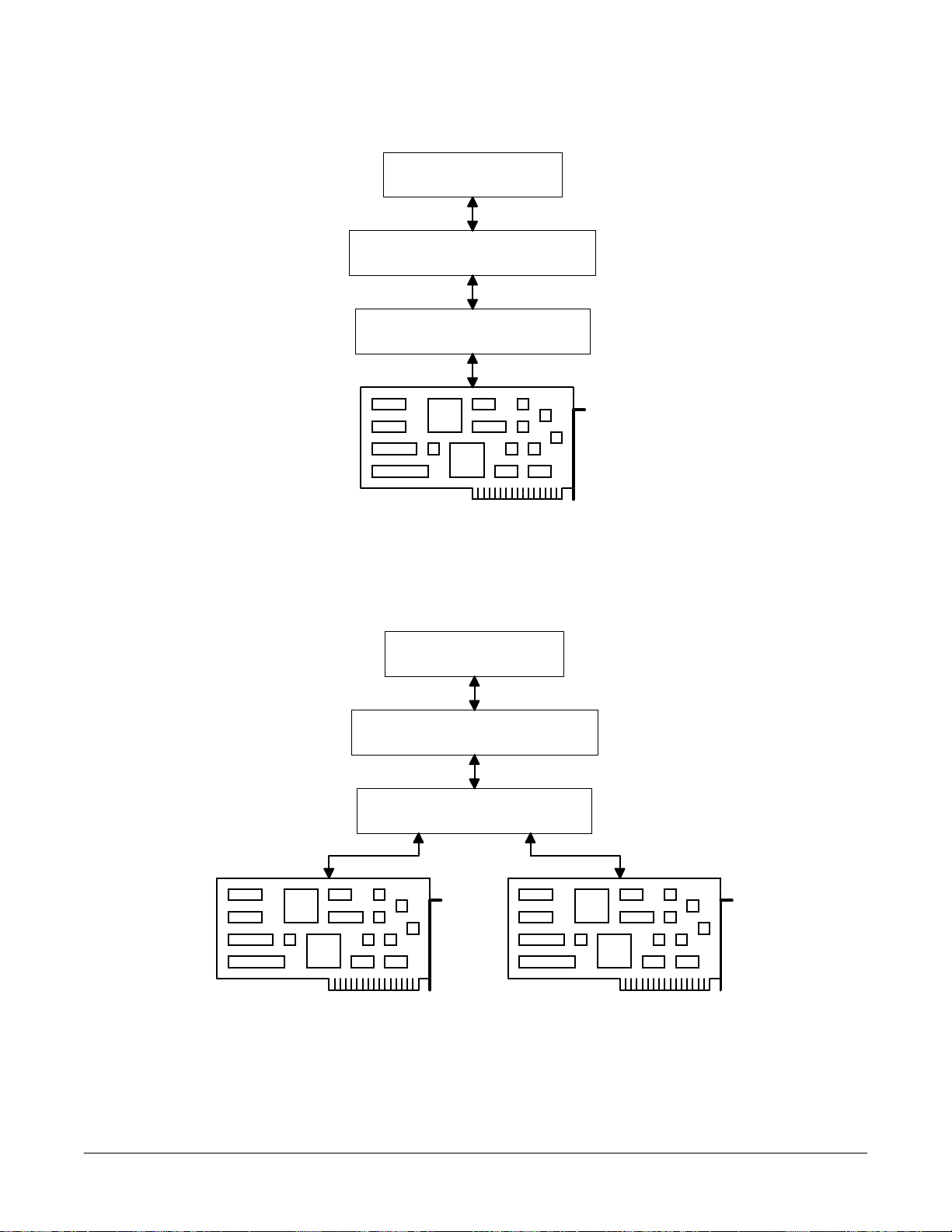
Figure 1. DAQDRIVE interface between an application program and one hardware device.
Application Program
Hardware independent driver
Hardware dependent driver
Application Program
Hardware independent driver
Hardware dependent driver
Figure 2. DAQDRIVE interface between an application program and multiple
devices of the same family.
Page 20
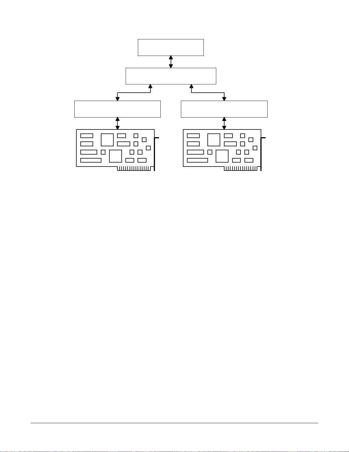
Application Program
DAQDRIVE Users Manual 20
Hardware independent driver
Hardware dependent driver Hardware dependent driver
Figure 3. DAQDRIVE interface between an application program and multiple
devices of different families.
Page 21

2 Before Beginning
2.1 Software Installation
DAQDRIVE Users Manual 21
The DAQDRIVE distrib uti on CD contains a Setup prog r am tha t allows the user to quickly and
easily install the necessary DAQDRIVE components onto the host computer. The Setup
program is compatible with Windows 3.x and Windows 95/98 and all ows the user to install
DAQDRIVE for DOS, Windows 3.x, and/or Windows 95/98.
From Windows 3.x:
1. Insert the compact disk into the computer's CD-ROM drive.
2. From the Windows program manager, select File then Run.
3. Assuming the CD-ROM drive is drive D, enter "D:\SETUP" in the command line
text box and click OK.
From Windows 95, Windows 98, and Windows NT 4.0:
1. Insert the compact disk into the computer's CD-ROM drive.
2. Click the Start button, point to Settings, then click Control Panel.
3. Double-click on Add/Remove Programs.
4. On the Install/Uninstall tab, click Install.
5. Click Next.
6. If the correct Setup program is found, click Finish. If not, click Browse and select
the Setup program in the root directory of the CD.
Follow the on- screen in structions to sele ct the DAQD RIVE components to be install ed. Whe n
the Setup program is complete, one or more of the following subdirectories will have been
created in the target directory:
...\DAQDRIVE\CONFIG DAQDRIVE Configuration Utility
...\DAQDRIVE\DAQEZ DaqEZ
...\DAQDRIVE\C_LIBS C library support for DOS applications
...\DAQDRIVE\TSR TSR driver support for DOS applications
...\DAQDRIVE\WINDLL Support for Windows 3.x and 16-bit Windows 95 applications
...\DAQDRIVE\VISDAQLT Support for 16-bit Visual Basic applications
...\DAQDRIVE\WIN32 Support for 32-bit Windows 95 applications
Page 22

2.2 DAQDRIVE Configuration Utilities
Before DA QDRIVE can operate an ad apter, a confi guration file must be generated to specif y
CAUTION:
DAQDRIVE Users Manual 22
the hardware configuration. Three separate Windows based utility programs are provided to
generate these configuration files:
1. DAQCFGW.EXE utility to edit DAQDRIVE hardware adapter configuration files
2. EXPBOARD.EXE utility to edit the data base defining available A/D expansion
boards and their parameters
3. SIGCON.EXE utility to edit the data base defining available A/D channel signal
conditioners and their parameters
IMPORTANT:
The DAQDRIVE configuration utilities must be used to edit the
DAQDRIVE hardware configuration files. Under no circumstances
should the user attempt to create and /or edit D AQDRIVE hard ware
configuration files directly.
2.2.1 Installation
The DAQDRIVE configuration utilities are automatically installed into the
..\DAQDRIVE\CONFIG subdirectory whenever the Setup program is executed. In addition,
the Setup program installs sample hardware configuration data files (.DAT), and their
associated report files (.RPT). These sample configuration files must be modified to create the
user’s configuration as DAQCFGW does not allow the creation of new hardware
configuration data files, but instead requires all files to be a modified version of an existing
file.
DAQCFGW does not al low the crea tion of new hardw are config uration data f iles, but instead
requires all files to be a modified version of an existing data file. The DAQDRIVE installation
program installs the necessary sample hardware configuration data files (.DAT), and their
associated report files (.RPT), into the ..\DAQDRIVE\CONFIG directory along with the
configuration utilities.
Older versions of DAQDRIVE may not be compatible with
files generated by the latest configuration utilities.
Page 23

2.2.2 Generating A DAQDRIVE Configuration File
DAQCFGW does not allow the creation of new data files but instead requires all files to be a
DAQDRIVE Users Manual 23
modified version of an existing data file (*.DAT). For this reason, one or more sample data
files are provided on the DAQDRIVE installation diskettes. To view and/or edit a
configuration data file:
1. Execute DAQCFGW by double-clicking on the DAQDRIVE configuration utility
icon located in the DAQDRIVE program group
2. Select File, Open
3. Select the drive and directory in the corresponding list boxes.
4. Type the name of an existing configuration data file (.DAT) in the file name text box
or select the file from the corresponding list box.
5. Choose OK.
Some or all of the following configuration options will appear in the Hardware Setup menu:
y
General
y
A/D Converter
y
A/D Expansion Boards
y
A/D Signal Conditioners
y
D/A converter
y
Timer
y
Digital I/O
y
Configuration Help
To select a subsystem for conf iguration, select it f rom the Hardware Setup menu or cl ick the
associated tool bar icon. If a specif ic subsystem is not availab le on the adapter or if there are
no user-definable options within that subsystem, the option will be disabled. The hardware
specific appendix for the adapter being configured lists the available options.
2.2.2.1 General Configuration
The general confi gurati on wind ow is used to def ine the i nterf ace be tween the ad apter a nd the
host system. All adapters require the general configuration options:
Base Address
The base I/O ad dress of the a dapter must be specif ied using the base add ress text box . If the
adapter i s PCMCIA, or PCI compatibl e, the user may speci fy a base ad dress of 0. Setti ng the
base address to 0 instructs DAQDRIVE to determine the ad apter 's b a se ad d r ess, interrupt, and
DMA settings automatically each time the device is opened.
IRQ Level
The adapter's interrupt level (IRQ) must be selected from the corresponding drop-down list
box. If the adapter does not support interrupts or if the base I/O address is set to 0, the
interrupt list box is not displayed.
Page 24

DMA Channel 1
The adapter 's pri mary DMA channel must be selecte d fr om the cor respond ing d rop-d own li st
DAQDRIVE Users Manual 24
box. If the adapter doe s not support DMA or if the base I/O ad dress is set to 0, the primary
DMA list box is not displayed.
DMA Channel 2
The adapter's secondary DMA channel must be selected from the correspond ing drop-down
list box. If the adapter does not support two DMA channels, or if the base I/O address is set
to 0, the secondary DMA list box is not displayed.
2.2.2.2 A/D Converter Configuration
The A/D converter wi ndow is used to define the configuration of the adapter 's analog i nput
channels. When these parameters define a specific jumper setting on the adapter, it is the
user's responsibility to assure the adapter is configured properly. The Configuration Help
window provides information regarding hardware modification requirements (see page 29).
The number and type of user-definab le options availa ble in this window i s dependent on the
hardware installed and is discussed in the hardware specific appendix for the adapter being
configured.
A/D Converters
Select the a nalog-to-dig ital (ADC) device on the A/D a dapter to be configured fr om this list
box. Most A/D adapters have only one ADC device (ADC 0).
Channels
Dialog b ox shows the number of A/D input channels availab le on the adapter in its current
configuration. A multiplexer (mux) feeds multiple analog inputs back into the actual ADC
device(s). The number of channels may be affected by the Input Mode.
Input Mode
Select the A/D input mode from the list box.
y
Single Ended: A/D converter measures the voltage from one input to ground. All
A/D channels normally share common ground.
y
Differential: A/D converter measures the voltage difference between two inputs that
are isolated from ground.
Signal Type
Select the signal type from the list box.
y
Unipolar: A/D converter measures only positive voltages.
y
Bipolar: A/D converter measures both positive and negative voltages.
Gain
This list box provide s opti onal signal a mpl i f ier settings. Note that this opti on i s only avail ab l e
on devices with hardw are sele ctable g ain setti ngs. D evices wi th software prog rammabl e gai ns
are configured at run-time.
Page 25

2.2.2.3 A/D Converter Expansion Configuration
The A/D converter expansion wi ndow i s used to defi ne the confi guration of any analog i nput
DAQDRIVE Users Manual 25
expansion adapters connected to the analog input channels. To assign an expansion board to
a main A/D channel click in the Expansion Board Names column and a choose from the drop
down list box. The first analog input expansion board must always be connected to A/D
channel 0, and additional expansion boards then connect to the next lowest channel.
Expansion adapters are defined in a data base using the EXPBOARD utility. The expansion
board data base may be viewed from the DataBase menu. However, to add or edit the
expansion board data base this utility must be run independently (see page 22).
The number and type of user-definab le options availa ble in this window i s dependent on the
hardware installed and the configuration of the expansion board as defined by the
EXPBOARD utility. When these parameters define a specific jumper setting on the expansion
board adapter, it is the user's responsibility to assure the adapter is configured properly.
The parameters in this window r e f er only to the expansion boar d adapter and do not ef f e ct the
A/D converter configuration of the main board. In most cases however, these two sets of
parameters must be examined together. For example, a gain of 2 in the A/D converter
configuration combined with a gain of 10 on the analog input expansion board results in an
overall gain of 20.
Channels
Dialog b ox shows the number of a nalog input channel s availabl e on the expansion board in its
current configuration. The values in this box are defined in the EXPBOARD utility. The
number of channels may be effected by the Input Mode.
Input Mode
Select the input mode from the list box.
y
Single Ended: input signals are measured from one input to ground. All inputs
normally share a common ground.
y
Differential: input signals are measured as the difference between two inputs that are
isolated from ground.
Signal Type
Select the signal type from the list box.
y
Unipolar: expansion board accepts only positive voltages.
y
Bipolar: expansion board accepts both positive and negative voltages.
Gain
This list box provide s opti onal signal a mpl i f ier settings. Note that this opti on i s only avail ab l e
on devices with hardware selectable gain settings. Devices with software programmable
gains are configurable at run-time.
Page 26
2.2.2.4 A/D Signal Conditioners
A signal conditioner may be connected to any A/D main channel, and/or to any A/D
DAQDRIVE Users Manual 26
expansion channel marked “Signal Conditioner Connectable” in the EXPBOARD utility (see
page 24). Expansion boards are normally used in conjunction with signal conditioners, but
are not required. To assign a signal conditioner to an A/D channel click in the Signal
Conditioner Name column and a choose from the drop down list box.
Signal conditioners are defined in a data base using the SIGCON utility. The signal
conditioner data base may be viewed from the DataBase menu. H owever, to add or edit the
signal conditioner data base this utility must be run independently (see page 24).
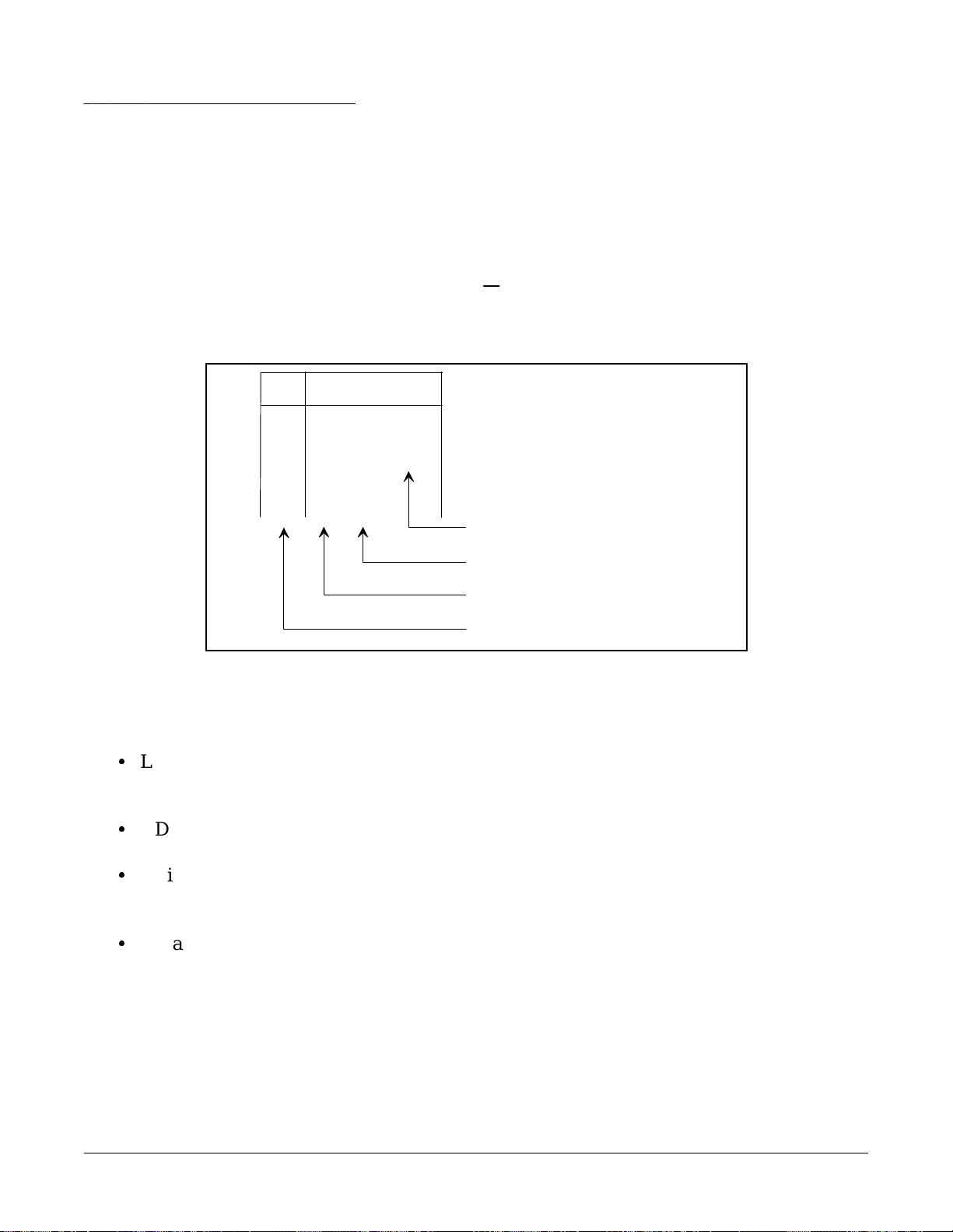
Mux CHCH
0-00-00
0
0-00-01
1
0-01
2
0-02
3
Expansion Channel
Main ADC Channel
ADC Device
Logical Channel
Figure 1. A/D Channel Numbering
To help understand the A/D channel numbering system the following terms are defined:
y
Logical Channel: The CH column designates the logical number that software
should use to access the analog input channel. When using
expansion boards you may have up to 256 logical channels.
y
ADC Device: The ADC device number. Most A/D adapters have only one
ADC device (ADC 0).
y
Main ADC Channel: Analog input channel on the A/D adapter board. A multiplexer
(mux) on the A/D adapter feeds multiple analog inputs back into
the actual ADC device(s).
y
Expansion Channel: Analog input channel provided by an expansion board
connection to a single main analog channel. Expansion boards
use digital I/O to address multiple expansion channels from a
single main channel through a multiplexer.
Page 27

2.2.2.5 D/A Converter Configuration
The D/A converter wi ndow is used to d efine the config uration of the adapte r's analog output
DAQDRIVE Users Manual 27
channels. When these parameters define a specific jumper setting on the adapter, it is the
user's responsibility to assure the adapter is configured properly. The Configuration Help
window provides information regarding hardware modification requirements (see page 20).
The number and type of user-definab le options availa ble in this window i s dependent on the
hardware installed and is discussed in the hardware specific appendix for the adapter being
configured.
D/A Channels
Select the D/A channel to configure from the list. Each D/A channel typically has its own
digital-to-analog converter (DAC).
Signal Type
Select the signal type from the list box.
y
Unipolar: DAC device outputs only positive voltages.
y
Bipolar: DAC device outputs both positive and negative voltages.
Ref. Source
Analog output from DAC is proportional to a reference voltage. Select the voltage source
from the list box.
y
Internal: Reference voltage generated by adapter board.
y
External: Reference voltage supplied by an external source.
Ref. Voltage
The reference voltage is used as scal ing multiplier for DAC output. For example, on a 12-bit
unipolar operation the analog output can be calculated from the equation:
V
OUT
= V
* (Digital_Count / 4096) * Gain
REF
Gain
This list box provide s opti onal signal a mpl i f ier settings. Note that this opti on i s only avail ab l e
on devices with hardware selectable gain settings. Devices with software programmable
gains are configurable at run-time.
2.2.2.6 Digital I/O Configuration
The digital I/O window is used to define the configuration of the adapter's digital input /
output channels. When these parameters def ine a specific jumper setting on the adapter, it is
the user's responsibility to assure the adapter is configured properly. The Configuration Help
window provides information regarding hardware modification requirements (see page 20).
The number and type of user-definab le options availa ble in this window i s dependent on the
hardware installed and is discussed in the hardware specific appendix for the adapter being
configured.
Page 28
Channel Configuration
Each digital I/O bit on an adapter can be individually accessed though the connector for
DAQDRIVE Users Manual 28
control/monitori ng of external dig ital devices. The digital I/O bits on each ad apter must be
configured into logical channels. Digital I/O channels can be set only 1 bit wide to access
single I/O lines at the connector, or logical channels that access multiple I/O bits
simultaneously are configurable.
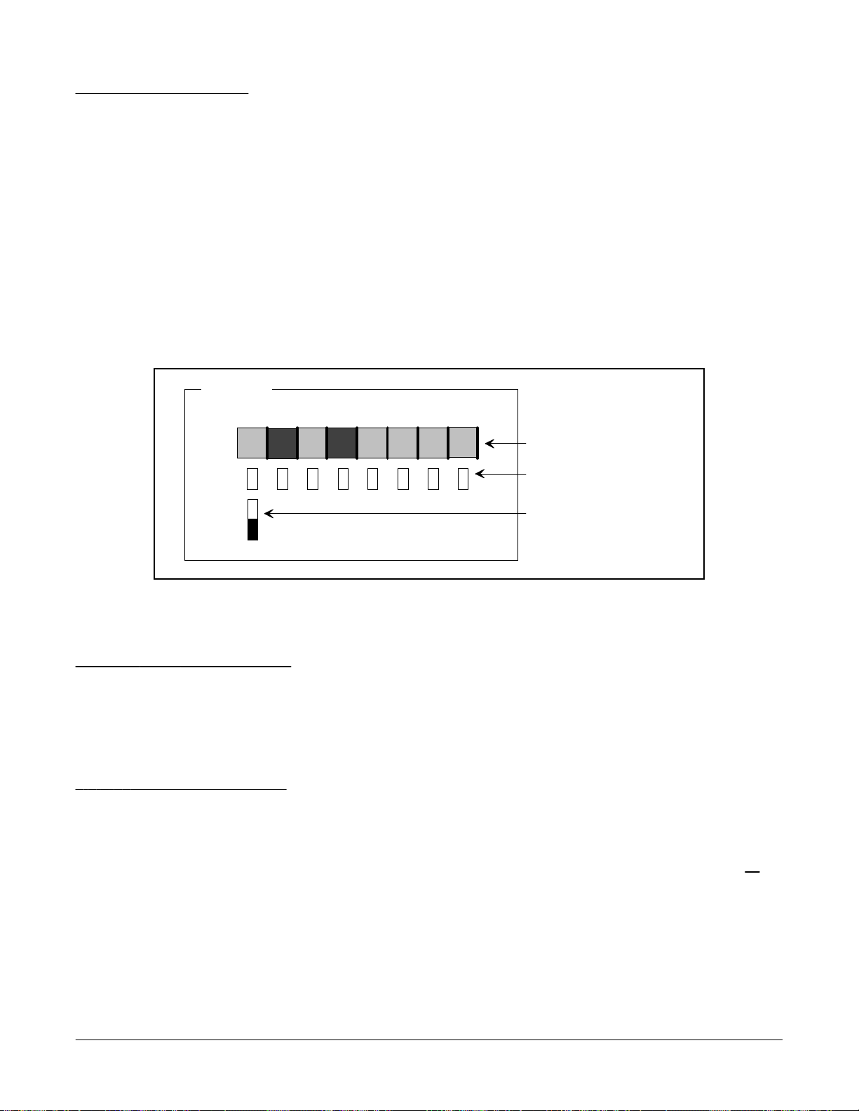
Assign a logical channel number to the target d igital I/O bit by clicki ng on the current logical
channel number. A drop down channel selection box will appear with the possible channel
configurations for this I/O bit (see Figure 2). The rest of the digital I/O bits will be
automatically upda ted with corr ect channel numbers reflecti ng any changes. Repeat thi s step
for each digital I/O bit.
Port 0
bit
CH
76
3
3
4
54321
InIn
3
In
OutOut
12
0
InIn
In
0
000
Direction Control
Logical Channel
Channel Select
Figure 2. Digital I/O Configuration Display
Input/Output Configuration
After all of the logical channels have been defined, they may be configured for input, output,
or input/output (I/O) b y cli cking on the di rection contr ol b utton for each l ogical channel. Al l
bits defined as a member of that logical channel will toggle between the available settings.
2.2.2.7 Timer Configuration
The timer configuration window is used to define the adapter's onboard counter / timer
circuits. Examples of settings found in this section include counter size and input clock
frequency. When these parameters define a specific jumper setting on the adapter, it is the
user's responsibility to assure the adapter is configured properly. The Configuration Help
window provides information regarding hardware modification requirements (see page 20).
The number and type of user-definab le options availa ble in this window i s dependent on the
hardware installed and is discussed in the hardware specific appendix for the adapter being
configured.
Page 29

2.2.2.8 Configuration Help
The hardware configuration of the adapter is the responsibility of the user. Some of these
DAQDRIVE Users Manual 29
hardware configuration settings may be handled through software, while others may require
switches or jumper blocks to be modified. The configuration help window provides the user
with the jumper block or switch numbers to modify if required.
It is the responsibility of the user to determine the correct settings for the current hardware
configuration. This help window is only a tool to assist the user in determining if and/or
where hardware modifications are required. The amount and type of information available in
this window is dependent on the hardware installed. No information is provided for
configuration options handled through software.
2.2.2.9 Saving The New Configuration
After the adapter configura tion is compl ete, the user may overwrite the curre nt configurati on
file or a new configuration file can be generated. To overwrite the existing configuration,
simply select File, Save from the menu. To generate a new configuration file:
1. Select File, Save As
2. Select the drive and directory in the corresponding list boxes.
3. Type the name of the new configuration data file in the file name text box.
4. Choose OK.
When the user saves an adapter configuration, a corresponding report file is generated using
the same file name with the extension .RPT. This report file provides an ASCII description of
the hardware configuration and may be viewed using any ASCII text editor.
2.2.2.10 Viewing the Report File
DAQCFGW also provides a utility for viewing the configuration report file (.RPT) generated
when the data file was saved.
1. Select File, View Report
2. Select the drive and directory in the corresponding list boxes.
3. Type the name of a report file (.RPT) in the file name text box or select a report from
the corresponding list box.
4. Choose OK.
5. Review the adapter's configuration using the Page-Up, Page-Down, and arrow keys
as well as the vertical and horizontal scroll bars.
6. When done, close the report viewer utility by selecting Close.
Page 30

2.2.3 A/D Expansion Board Database Utility
DAQCFGW uses a database of analog input expansion boards to assist the user in the
DAQDRIVE Users Manual 30
configuration of a complete data acquisition system. Omega expansion boards are predefined
in the database and may not be modified by the user. New adapters may be added to the
database using the EXPBOARD utility. Any modification to an expansion board
configuration is automatically updated in the database file and made available to the
DAQDRIVE configuration utility. To create and/or edit a user-defined analog input
expansion board:
1. Execute EXPBOARD by double-clicking on the expansion board utility icon located
in the DAQDRIVE program group.
2. Select ADD NEW, EDIT, or DELETE to update the expansion board database.
The parameters for each expansion board in the database refer only to the expansion board
adapter and do not effect the A/D converter confi guration of the main boar d. In most cases
however, these two sets of para meters must be examine d togethe r. For exampl e, a gain of 2 in
the A/D converter configuration combined with a gain of 10 on the expansion board results in
an overall gain of 20.
When these parameters define a specific jumper setting on the expansion board adapter, it is
the user's responsibility to assure the adapter is configured properly. Refer to the expansion
board documentation for details and parameter values.
Long Device Name
Each expansion ad apter must have a unique Long Device Name of 1 - 30 characters. T he long
device name used only for descriptive purposes.
Device Name
Each expansion adapter must have a unique Device Name of 14 characters or less.
Input Mode
Select the A/D input mode from the list box.
y
Single Ended: A/D converter measures voltage from one input to ground. All A/D
channels normally share common ground.
y
Differential: A/D converter measures voltage across two inputs that are isolated from
ground.
y
DI/SE Selectable
Signal Type
Select the signal type from the list box.
y
Unipolar: Expansion device reads only positive voltage.
y
Bipolar: Device reads both positive and negative voltages.
y
Selectable: Either of the signal types is available.
Page 31

Num Gains
The Num Gains box refers to the number of gains availa ble to the programmer at run-time.
DAQDRIVE Users Manual 31
Therefore, if the expansion board has 4 software selectable gains this field should be set to 4.
But, if the expansion board has 4 hardware (jumper or switch) selectable gains, the Num
Gains field should be set to 1. In both cases fill in Gains list with all available gains.
Differential
Specify the number of differential A/D Expansion channels available on the expansion board.
A typical expansion board will connect to one A/D main channel on the A/D adapter and
provide up to 8 differential expansion inputs.
Single Ended
Specify the number of Single Ended A/D Expansion channels available on the expansion
board. A typical expansion board will connect to one A/D main channel on the A/D adapter
and provide up to 16 single ended expansion inputs.
Gains List
List all analog input amplier gains available on expansion board. When the DAQDRIVE
Configuration utility is run, the A/D expansion board configuration section will include a
Gains list box to select the expansion board gain setting if the expansion board has hardware
selectable gains. Otherwise, the programmer may select any of the available expansion board
gains through software at run-time.
Maximum One Channel Frequency
Maximum sampling rate for a single A/D input.
Maximum Multi-Channel Frequency
Maximum scan rate for multiple A/D inputs. Normally slower than the one channel
maximum frequency since the multiplexer must switch between A/D inputs.
Channel Signal Type
Select the channel signa l type from the li st box. Selection deter mines w hether the DAQD RIVE
Configuration utility will allow the use of signal conditioners.
y
Direct Analog Signal Connection: Expansion device supports only direct analog
signal inputs.
y
Signal Conditioner Connectable: Expansion device supports the use of signal
conditioners.
Page 32

2.2.4 Signal Conditioner Database Utility
DAQCFGW uses a database of analog input signal conditioners to assist the user in the
DAQDRIVE Users Manual 32
configuration of a complete data acquisition system. Many standard signal conditioners are
predefined in the database and may not be modified by the user. New conditioners may be
added to the database using the SIGCON utility. Any modification to a signal conditioner’s
parameters are automatically updated in the database file and made available to the
DAQDRIVE configuration utility. To create and/or edit a user-defined analog input signal
conditioner:
1. Execute SIGCON by double-clicking on the signal conditioner utility icon located in
the DAQDRIVE program group.
2. Select ADD NEW, EDIT, or DELETE to update the signal conditioner database.
The parameters for each signal conditioner in the database refer only to the signal conditioner
and do not effect the A/D converter configuration or the expansion board configuration. In
most cases however, these sets of parameters must be examined together to determine the
overall configuration. Refer to the signal conditioner documentation for details and parameter
values.
Long Device Name
Each device must have a unique Long Device Name of 1 - 30 characters. The long device
name used only for descriptive purposes.
Device Name
Each device must have a unique Device Name of 14 characters or less.
Device Type
Select the device type from the list box.
y
Linear
y
Nonlinear
Minimum Input
Minimum value the signal conditioner is capable of reading. Type of signal is specified by
Input Units.
Maximum Input
Maximum value the si gnal conditioner is capable of reading. Type of signal is specified b y
Input Units.
Page 33

Input Units
Select the measurement units f or the signal ty pe from the list box. Below is a sample of the
DAQDRIVE Users Manual 33
choices.
y
Minimum Output
Minimum value the signal conditioner returns to the A/D input . Type of sig nal is specified
by Output Units.
Maximum Output
Maximum value the signal condi tioner returns to the A/D input . Type of si gnal is specified
by Output Units.
Output Units
Specifies the me asurement units for the si gnal type returne d to the A/D converter. Currently
signal is always of type volts.
V (volts)
y
A (amps)
y
Degree C (temperature)
y
Kg (kilogram)
y
Hz (frequency)
y
m/sec2 (acceleration)
Bandwidth
Maximum frequency at which the signal conditioner can process data.
Maximum Scan Rate
Maximum frequency at which multiple devices may be scanned. This rate is normally sl ower
than the bandwidth rating due to switching and settling times.
Page 34

Number of Coefficients
The functional operation of a signal conditioner is defined by a polynomial equation (see
DAQDRIVE Users Manual 34
Figure 3). Refer to the signal conditioner documentation for the polynomial coefficients
defining the polynomial equation. The number of coefficients specified for the equation is
manufacturer dependent. Specify the Number of Co efficients to be used i n the polynomial
equation in this text box.
Temp ( )
0
C
Temp ( )
Sensor
0
Vy = A + A Vx + A Vx + A Vx + ...A Vx
C
01
where A = Polynomial Coefficients
n
Signal
Conditioner
2
2
Vx
3
3
n
A/D
Input
n
Digital
Count
Figure 3. The Polynomial Equation
Polynomial Coefficients
Up to 12 poly nomial coef fi cients i n the polynomi al eq uation for the si gnal conditi oner may b e
specified. Fill in the Number of Coefficients text box to match the number of coefficient
values in the Polynomial Coefficients list.
Page 35

2.3 Creating DOS Applications Using The C Libraries
2.3.1 Microsoft Visual C/C++
IMPORTANT:
DAQDRIVE Users Manual 35
To generate application programs using Microsoft Visual C/C++, the applications must be
linked to one of the following D AQDRIVE libr aries AND one or more hardware dependent
libraries. These libraries MUST match the memory model selected for the application
program. The DAQDRIVE installation program installs the following files into the
DAQDRIVE\C_LIBS directory:
DAQDRVCS.LIB - small model DAQDRIVE library
DAQDRVCM.LIB - medium model DAQDRIVE library
DAQDRVCC.LIB - compact model DAQDRIVE library
DAQDRVCL.LIB - large model DAQDRIVE library
Three additional files are installed in the DAQDRIVE\C_LIBS directory for the programmer's
convenience. These files contain the prototypes of all the DAQDRIVE procedures, data
structure definitions, and constants mentioned throughout this document. These files must be
included in all application programs.
DAQDRIVE.H - procedure prototypes
DAQOPENC.H - DaqOpenDevice definition for C
USERDATA.H - data structures and pre-defined constants
2.3.1.1 The hardware dependent include file
The C library version of the DaqOpenDevice procedure is implemented as a macro using the
"token-pasting" operator to create a unique open command for each hardware device.
Application programs must include the file DAQOPENC.H and the hardware dependent
include file defined in the target hardware's appendix. The DAQDRIVE installation program
installs these files into the DAQDRIVE\C_LIBS directory.
2.3.1.2 Creating byte-aligned data structures
Because DAQDRIVE supports multiple languages, all data structures are byte-aligned
(packed). The application program must also set structure packing to byte-aligned for proper
operation.
For proper operation, all application programs must be compiled using
byte- aligned data structures.
To select byte aligned structures within the Visual C/C++ environment, first select Options,
roject, Compiler, the n set the structure member a lignment fie ld to 1 byte. For byte aligned
P
structures from the Visual C/C++ command line, use the '/Zp1' option.
Page 36

2.3.2 Borland C/C++
To generate application programs using Borland C/C++, the applications must be linked to
IMPORTANT:
DAQDRIVE Users Manual 36
one of the following DAQDRIVE libraries AND one or more hardware dependent libraries.
These libraries MUST match the memory model selected for the application program. The
DAQDRIVE installation program installs the following files into the DAQDRIVE\C_LIBS
directory:
DAQDRVBS.LIB - small model DAQDRIVE library
DAQDRVBM.LIB - medium model DAQDRIVE library
DAQDRVBC.LIB - compact model DAQDRIVE library
DAQDRVBL.LIB - large model DAQDRIVE library
Three additional files are installed in the DAQDRIVE\C_LIBS directory for the programmer's
convenience. These files contain the prototypes of all the DAQDRIVE procedures, data
structure definitions, and constants mentioned throughout this document. These files must be
included in all application programs.
DAQDRIVE. H - procedure prototypes
DAQOPENC.H - DaqOpenDevice definition for C
USERDATA.H - data structures and pre-defined constants
2.3.2.1 The hardware dependent include file
The C library version of the DaqOpenDevice procedure is implemented as a macro using the
"token-pasting" operator to create a unique open command for each hardware device.
Application programs must include the file DAQOPENC.H and the hardware dependent
include file defined in the target hardware's appendix. The DAQDRIVE installation program
installs these files into the DAQDRIVE\C_LIBS directory.
2.3.2.2 Creating byte-aligned data structures
Because DAQDRIVE supports multiple languages, all data structures are byte-aligned
(packed). The application program must also set structure packing to byte-aligned for proper
operation.
For proper operation, all application programs must be compiled using
byte- aligned data structures.
To guarantee structures are byte aligned within the Borland C/C++ environment, select
Options, Compiler, Code Generation, then confirm the Word alignment box is not checked.
For byte aligned structures from the Borland C/C++ command line, use the '-a-' option.
Page 37

2.3.2.3 Program optimization
When selecting the optimizati on options for the B orland C/C++ compiler, prob lems may ari se
IMPORTANT:
DAQDRIVE Users Manual 37
if the 'Invariant code motion' option is selected and DAQDRIVE is operated in one of the
background mod e s (IRQ or D MA) . To di sab le the 'Invari a nt code motion' opti mization withi n
the Borland C/C++ environment, sele ct Options, Compiler, Optimizations, then confirm the
'Invariant code motion' b ox is not checked. From the Borland C/C++ command lin e, make
sure the '-Om' and '-O2' options are not used.
It is strongly recommended that the 'Invariant code motion' optimization
option be disabled when using the Borland C/C++ compiler.
Page 38

2.4 Creating DOS Applications Using The TSR Drivers
DAQDRIVE provides a TSR (Terminate-and-Stay-Resident) driver for creating DOS
DAQDRIVE Users Manual 38
applications in any language that supports software interrupt (int) calls. In addition, libraries
are provide d to interface the following high-level l anguages to the DA QDRIVE TSR: Vi sual
Basic for DOS, Quick Basic version 4.5, Turbo Pascal version 7.0 and newer, and most C
compilers.
Although the interface to each of these languages is similar, the methods for generating
application programs varies with the application language. The following sections describe
the steps required to load the TSRs into memory and generate an application in each of the
supported languages.
2.4.1 Loading The TSRs Into Memory
The DAQDRIVE installation program installs the TSR driver into the DAQDRIVE\TSR
directory: The first step in creating applications which use the DAQDRIVE TSR is to load the
driver into memory using the command line:
DAQDRIVE
In this mode, DAQDRIVE searches software interrupts 60H through 64H for an available
interrupt. If an unused interrupt is located, DAQDRIVE takes control of this interrupt and
displays a message indicating the installation was successful and which software interrupt is
being used. If there are no available interrupts in this range, an error message is displayed
and the DAQDRIVE TSR is not installed.
If the user wants to control the software i nterrupt number, or if a ll of the sof tware inter rupts
between 60H and 64H are used, the user may specify a software interrupt with the following
command line:
DAQDRIVE [/I=interrupt]
where interrupt specifies the software interrupt number in hexadecimal format. If the
user-specified interrupt is not available, an error message is displayed and the DAQDRIVE
TSR is not installed.
Examples:
DAQDRIVE /I=63 installs DAQDRIVE on interrupt 63H
DAQDRIVE /I=4F installs DAQDRIVE on interrupt 4FH
DAQDRIVE /I=b9 installs DAQDRIVE on interrupt B9H
Page 39

After the DAQDRIVE TSR has been loaded, the user must load one or more TSRs for the
hardware device(s) to be accessed. The DAQDRIVE installation program installs the TSR
DAQDRIVE Users Manual 39
driver(s) for the selected hardware device(s) into the DAQDRIVE\TSR directory. For this
discussion, we will assume the hardware driver's TSR name is HARDWARE.EXE. To load
this TSR simply execute the command:
HARDWARE
The hardware TSR will search for the DAQDRIVE TSR in memory and, if it is located, will
install itself using the same software interrupt. If DAQDRIVE was not previously installed,
the hardware TSR will respond with an error message and will not be installed.
Multiple TSR drivers may be installed for multiple devices by repeating the above process for
each hardware driver.
2.4.2 Removing The TSRs From Memory
The DAQDRIVE and hardware devi ce TSR(s) may be removed fr om memory using the '/R'
option to make additional memory available to other applications. The only restriction is that
the TSRs must be removed in the reverse order of their installation. Consider an example
where the following TSRs have been loaded:
DAQDRIVE - installs the DAQDRIVE TSR
DAQPTSR - installs the DAQP-208 TSR
IOP-241 - installs the IOP-241 TSR
To remove these TSRs f rom memory, the user si mply reverse s the install ation order and add s
the '/R' option to each command line:
IOP-241 /R - removes the IOP-241 TSR
DAQPTSR /R - removes the DAQP-208 TSR
DAQDRIVE /R - removes the DAQDRIVE TSR
Page 40

2.4.3 Microsoft C/C++
To generate application programs using the DAQDRIVE TSR with Microsoft C/C++, the
DAQDRIVE Users Manual 40
application must be linked with the DAQDRIVE library DAQTSRC.LIB installed in the
DAQDRIVE\T SR\C dire ctory by the DAQD RIVE insta llation progr am. Thi s libr ary is model
independent and should work with most C compilers for DOS.
Three additional files are installed in the DAQDRIVE\TSR\C directory for the programmer's
convenience. These files contain the prototypes of all the DAQDRIVE procedures, data
structure definitions, and constants mentioned throughout this document. These files must be
included in all application programs.
DAQDRIVE. H - procedure prototypes
DAQOPENT.H - DaqOpenDevice prototype
USERDATA.H - data structures and pre-defined constants
2.4.3.1 Creating byte-aligned data structures
Because DAQDRIVE supports multiple languages, all data structures are byte-aligned
(packed). The application program must also set structure packing to byte-aligned for proper
operation.
IMPORTANT:
For proper operation, all application programs must be compiled using
byte- aligned data structures.
To define byte aligned structures with Microsoft C use the '/Zp1' command line option.
Within the Microsoft Visual C/C++ en vi r onme nt, select Options, Project, Compiler and se t the
structure member alignment field to 1 byte.
Page 41

2.4.4 Borland C/C++ and Turbo C
To generate appli cation programs using the DAQDRIVE T SR with Borl and C/C++ or Turbo
DAQDRIVE Users Manual 41
C, the application must be linked with the DAQDRIVE library DAQTSRC.LIB installed in the
DAQDRIVE\T SR\C dire ctory by the DAQD RIVE insta llation progr am. Thi s libr ary is model
independent and should work with most C compilers for DOS.
Three additional files are installed in the DAQDRIVE\TSR\C directory for the programmer's
convenience. These files contain the prototypes of all the DAQDRIVE procedures, data
structure definitions, and constants mentioned throughout this document. These files must be
included in all application programs.
DAQDRIVE. H - procedure prototypes
DAQOPENT.H - DaqOpenDevice prototype
USERDATA.H - data structures and pre-defined constants
2.4.4.1 Creating byte-aligned data structures
Because DAQDRIVE supports multiple languages, all data structures are byte-aligned
(packed). The application program must also set structure packing to byte-aligned for proper
operation.
IMPORTANT:
For proper operation, all application programs must be compiled using
byte- aligned data structures.
To guarantee structures are byte aligned within the Borland C/C++ environment, select
Options, Compiler, Code Generation, then confirm the Word alignment box is not checked.
Within the Turbo C environment, select Options, Compiler, Code Generation, then set the
Alignment opti on to byte. F or byte ali gned structures f rom the Borl and C/C++ or Turb o C
command lines, use the '-a-' option.
2.4.4.2 Program optimization
When selecting the optimizati on options for the B orland C/C++ compiler, prob lems may ari se
if the 'Invariant code motion' option is selected and DAQDRIVE is operated in one of the
background mod e s (IRQ or D MA) . To di sab le the 'Invari a nt code motion' opti mization withi n
the Borland C/C++ environment, sele ct Options, Compiler, Optimizations, then confirm the
'Invariant code motion' b ox is not checked. From the Borland C/C++ command lin e, make
sure the '-Om' and '-O2' options are not used.
IMPORTANT:
It is strongly recommended that the 'Invariant code motion' optimization
option be disabled when using the Borland C/C++ compiler.
Page 42

2.4.5 Quick Basic
To generate applica tion programs using the DAQD RIVE TSR with Quick B asic 4.5, the Quick
DAQDRIVE Users Manual 42
Library DAQQB45.QLB must be loaded from the Quick Basic command line using the /L
option. DAQQB45.QLB is installed into the DAQDRIVE\TSR\QB45 directory by the
DAQDRIVE installation program. A standard library, DAQQB45.LIB, is also installed in this
directory for creating stand-alone executable programs (.EXE) using Quick Basic.
Two additional files are installed into the DAQDRIVE\TSR\QB45 directory for the
programmer's convenience. These files contain the prototypes of all the DAQDRIVE
procedures, data structure definitions, and constants mentioned throughout this document.
These files must be included in all application programs.
DAQQB45.INC - procedure declarations
USERDATA.INC - data structures and pre-defined constants
2.4.5.1 Quick Basic's on-line help
Although undocumented , the Quick Basic 4. 5 on-line help appears to use software interrupt
60H and may interfere with the DAQDRIVE TSR. If suspicious errors occur while using
Quick Basic, users are advised to install DAQDRIVE on software interrupt 61H, 62H, 63H, or
64H.
IMPORTANT:
Although undocumented, the Quick Basic 4.5 on-line help appears to use
software interrupt 60H and may interfere with DAQDRIVE.
2.4.5.2 Quick Basic and the under-score character
One difference between the Quick Basic version and other versions of DAQDRIVE is that
Quick Basic reser ves the underscore char acter ( _ ). T he underscore character appears in data
declarati ons and constants throughout this document b ut has been removed from the Quick
Basic version of DAQDRIVE.
2.4.5.3 Adjusting the size of Quick Basic's stack and heap
DAQDRIVE uses the application program's stack for storing local variables and for passing
variables between DAQDRIVE procedures. By default, Quick Basic 4.5 only allocates 2K of
memory for the applicati on's stack which may be insuf ficient und er come circumstances. It is
recommended that the user increase the size of the application's stack by at least 2K using the
CLEAR command. Note that the CLEAR command also clears all data memory and should
therefore be used at the beginning of the application program.
In addition, application programs written using Quick Basic 4.5 allocate all available DOS
memory for use as a local heap. This causes DAQDRIVE to report an error 300 (memory
allocation er ror) when the appli cation attempts to open a device . Th e appli cation must reduce
Page 43

the size of the heap usi ng Quick Basi c's SETMEM function b efore executing DaqOpenDevice.
As a guide, the application should reduce the heap by 10, 000 bytes for each hardware device
p
)
DAQDRIVE Users Manual 43
opened and once the DaqOpenDevice procedure has been executed , the allocated heap space
must not be returned to Quick Basic until the DaqCloseDevice procedure has been completed.
'****************************************************************************
' Increase the size of the Quick Basic stack by 2K
'****************************************************************************
CLEAR ,,2048
'****************************************************************************
' Decrease the size of the heap so DAQDRIVE can allocate required memory
'****************************************************************************
HeapSize = SETMEM(-10000)
'****************************************************************************
' Perform all DAQDRIVE functions
'****************************************************************************
DaqOpenDevice ....
DaqCloseDevice ....
'****************************************************************************
' Optionally restore heap
'****************************************************************************
Hea
Size = SETMEM(+10000
2.4.5.4 The DaqOpenDevice Command
DAQDRIVE's DaqOpenDevice command requires two null-terminated string variables:
DeviceType and ConfigFile. Because Quick Basic does not support null-terminated strings,
the user must create these str ings by appendi ng a null characte r, CHR$(0), to the end of each
string before passing it to DAQDRIVE. For example:
A$ = "FILENAME.DAT" normal Quick Basic string
B$ = "FILENAME.DAT" + CHR$(0) null-terminated string
Furthermore, Quick Basic is unable to pass the address of a string variable as a far pointer. To
overcome this problem, the DaqOpenDevice procedure is declared differently for the Quick
Basic version of DAQDRIVE:
DaqOpenDevice ( BYVAL TSRNumber AS Integer,
SEG LogicalDevice AS Integer,
BYVAL DeviceTypeSegment AS Integer,
BYVAL DeviceTypeOffset AS Integer,
BYVAL ConfigFileSegment AS Integer,
BYVAL ConfigFileOffset AS Integer )
Page 44

The string variables normally found in the DaqOpenDevice command have been replaced by
integer values which contain the segment and offset address of the string. The application
DAQDRIVE Users Manual 44
program can obtai n these addresses using the VARSEG and SADD functions as shown in the
following example.
'****************************************************************************
' Step 1: Open the device
'****************************************************************************
LogicalDevice% = 0
DeviceType$ = "DA8P-12B" + CHR$(0)
ConfigFile$ = "da8p-12b.dat" + CHR$(0)
Status% = DaqOpenDevice(&HF006, LogicalDevice%,
VARSEG(DeviceType$), SADD(DeviceType$),
VARSEG(ConfigFile$), SADD(ConfigFile$))
2.4.5.5 Storing a variable's address in a data structure
Another short-coming of Quick Basic is its inability to easily operate on a variable's address.
Because of this limitation, all of the variables declared as 'far pointers' in the DAQDRIVE data
structures have been divided into two integer values: a segment address and an offset
address. An example of this is the channel array variable in the ADCRequest structure
unsigned short far *channel_array_ptr;
which becomes
ChannelArrayPtrOffset AS Integer
ChannelArrayPtrSegment AS Integer
For an array named Channel, the application fills in the array's address using the VARSEG
and VARPTR procedures as follows:
DIM Channel[10] AS Integer
ADCRequest.ChannelArrayPtrOffset = VARPTR(Channel[0])
ADCRequest.ChannelArrayPtrSegment = VARSEG(Channel[0])
2.4.5.6 Dynamic memory allocation
To prevent Quick Basic from dynamically relocating variables, it is good practice to declare all
variables before the first instruction of the application program.
Page 45

2.4.6 Visual Basic for DOS
To generate application programs usi ng the DAQDRIVE T SR with Visual B asic for DOS, the
DAQDRIVE Users Manual 45
Quick Library DAQVBDOS.QLB must be loaded from the Visual Basic command line using
the /L option. D AQVBDOS.QLB is installed into the DAQDRIVE \TSR\VBDOS di rectory by
the DAQDRIVE installation program. A standard object library, DAQVBDOS.LIB, is also
installed in this directory for creating executable programs (.EXE) using Visual Basic for DOS.
Two additional files are installed into the DAQDRIVE\TSR\VBDOS directory for the
programmer's convenience. These files contain the prototypes of all the DAQDRIVE
procedures, data structure definitions, and constants mentioned throughout this document.
These files must be included in all application programs.
DAQVBDOS.INC - procedure declarations
USERDATA.INC - data structures and pre-defined constants
2.4.6.1 Visual Basic for DOS and the under-score character
One diffe rence betw een the Visua l Ba sic for D OS version and other versi ons of DAQD RIVE i s
that Visual Basi c reserves the und erscore character ( _ ). The underscore char acter appears i n
data declarations and constants throughout this document but has been removed from the
Visual Basic for DOS version of DAQDRIVE.
2.4.6.2 Adjusting the size of the Visual Basic's stack and heap
DAQDRIVE uses the application program's stack for storing local variables and for passing
variables between DAQDRIVE procedures. By default, Visual Basic for DOS only allocates 2K
of memory for the applicati on's stack which may be insuff ici ent under come ci rcumstances. It
is recommended that the user increase the size of the applicati on's stack by at least 2K using
the CLEAR command. Note that the CLEAR command also clears all data memory and
should therefore be used at the beginning of the application program.
In addition, application programs written using Visual Basic for DOS allocate all available
DOS memory for use as a local heap. This causes DAQDRIVE to report an error 300 (memory
allocation error) when the application attempts to open a device. The application program
must reduce the size of the heap using Visual Basic's SETMEM function before executing
DaqOpenDevice. As a guide, the application should reduce the heap by 10,000 bytes for each
hardware device to be opened and once the DaqOpenDevice procedure has been executed , the
allocated hea p space must not be re tur ned to Visual B asi c until the D a qCl oseD e vi ce pr oce d ur e
has been completed.
Page 46

'****************************************************************************
DAQDRIVE Users Manual 46
' Increase the size of the Visual Basic stack by 2K
'****************************************************************************
CLEAR ,,2048
'****************************************************************************
' Decrease the size of the heap so DAQDRIVE can allocate required memory
'****************************************************************************
HeapSize = SETMEM(-10000)
'****************************************************************************
' Perform all DAQDRIVE functions
'****************************************************************************
DaqOpenDevice ....
DaqCloseDevice ....
'****************************************************************************
' Optionally restore heap
'****************************************************************************
HeapSize = SETMEM(+10000)
2.4.6.3 The DaqOpenDevice Command
DAQDRIVE's DaqOpenDevice command requires two null-terminated string variables:
DeviceType and ConfigFile. Because Visual Basic does not support null-terminated strings,
the user must create these str ings by appendi ng a null characte r, CHR$(0), to the end of each
string before passing it to DAQDRIVE. For example:
A$ = "FILENAME.DAT" normal Visual Basic string
B$ = "FILENAME.DAT" + CHR$(0) null-terminated string
Furthermore, Visual Basi c for DOS is unable to pass the address of a string variable as a far
pointer. To overcome this problem, the DaqOpenDevice procedure is declared differently for
the Visual Basic for DOS version of DAQDRIVE:
DaqOpenDevice ( BYVAL TSRNumber AS Integer,
SEG LogicalDevice AS Integer,
BYVAL DeviceTypePtr AS Long,
BYVAL ConfigFilePtr AS Long )
The string variables normally found in the DaqOpenDevice command have been replaced by
long integer values which contain the string's address. The application program can obtain
the string address using the SSEGADD function as shown in the following example.
Page 47

'****************************************************************************
DAQDRIVE Users Manual 47
' Step 1: Open the device
'****************************************************************************
LogicalDevice% = 0
DeviceType$ = "DA8P-12B" + CHR$(0)
ConfigFile$ = "da8p-12b.dat" + CHR$(0)
Status% = DaqOpenDevice(&HF006, LogicalDevice%,
SSEGADD(DeviceType$),
SSEGADD(ConfigFile$))
2.4.6.4 Storing a variable's address in a data structure
Another short-coming of Visual Basic for DOS is its inability to easily operate on a variable's
address. Because of this limitation, all of the variables declared as 'far pointers' in the
DAQDRIVE data structures have been divided into two integer values: a segment address and
an offset address. An example of this is the channel array variable in the ADCRequest
structure
unsigned short far *channel_array_ptr;
which becomes
ChannelArrayPtrOffset AS Integer
ChannelArrayPtrSegment AS Integer
For an array named Channel, the application fills in the array's address using the VARSEG
and VARPTR procedures as follows:
DIM Channel[10] AS Integer
ADCRequest.ChannelArrayPtrOffset = VARPTR(Channel[0])
ADCRequest.ChannelArrayPtrSegment = VARSEG(Channel[0])
2.4.6.5 Dynamic memory allocation
To prevent Visual Basic for DOS from dynamically relocating variables, it is good practice to
declare all variables before the first instruction of the application program.
Page 48

2.4.7 Turbo Pascal
DAQDRIVE supports applications written with Turbo Pascal version 7.0 and newer through
IMPORTANT:
DAQDRIVE Users Manual 48
the unit files DAQDRIVE.TPU and DAQDATA.TPU installed by the DAQDRIVE installation
program into the DAQD RIVE\TSR\PASCAL dir ectory. DAQDRIVE.TPU d efines the Turbo
Pascal interface to the DAQDRIVE functions while DAQDATA.TPU defines the data
structures (Pascal 'records') and constants mentioned throughout this document.
In order to access DAQDRIVE's functions, data structures, and constants, all application
programs must include the following statement:
USES DAQDRIVE, DAQDATA;
2.4.7.1 Turbo Pascal and floating-point math
The Turbo Pascal floating-point emulation library only supports variables of type 'real'. To
use the single and doubl e precision variables requi red by DAQDRIVE, the 8087 floating-point
math mode must be enabled by selecting Options, Compiler, 8087/80287 or by defining the
numeric coprocessor switch {$N+}.
2.4.7.2 Adjusting the size of the Turbo Pascal heap
By default, application programs written using Turbo Pascal allocate all available DOS
memory for use as a local heap. This causes DAQDRIVE to report an error 300 (memory
allocation er ror) when the appl ication attempts to open a devi ce. The user must reduce the
size of the application's heap by selecting Options, Memory si zes and setting the 'Hig h heap
limit' option to a value less than 655,360 (640K). As a guide, reduce the heap by 10,000 bytes
for each hardware device to be opened by the application.
The user must modify the default Turbo Pascal heap settings to prevent
the application from allocating all available DOS memory at start-up.
2.4.7.3 Using other Turbo Pascal versions
When using a version of Turbo Pascal other than 7.0, the user must create new unit files
(.TPUs) by re-compiling the source files DAQDRIVE.PAS and DAQDATA.PAS. These files,
along with the interface library DAQTSR.OBJ, are also installed into the
DAQDRIVE\TSR\PASCAL directory by the DAQDRIVE installation program.
Page 49

2.5 Creating 16-bit Windows 3.x/95/98 Applications
DAQDRIVE supports 16-bit Windows application programs written in most languages which
DAQDRIVE Users Manual 49
support the Windows DLL (Dynamic Link Library) interface. When the Windows application
programs are executed , they must be abl e to dynamicall y link to DAQDRIVE.D LL and one or
more hardware dependent DLLs. Windows searches for any necessary DLLs in the following
locations:
1. the current directory
2. the Windows directory (directory containing WIN.COM)
3. the Windows\System directory (directory containing GDI.EXE)
4. the directory of the application program
5. all directories specified by the PATH environment variable
6. all directories mapped to network drives
The DAQDRIVE installation program installs the DAQDRIVE DLL and the DLLs for any
selected hardware device into the Windows\System directory. In addition, an import library,
DAQDRIVE.LIB, is installed into the DAQDRIVE\WINDLL directory. This import library
can be used by many Windows compilers to simplify the linking of application programs to
the APIs available within the DAQDRIVE DLL.
DAQDRIVE has been tested with application programs written in Microsoft Visual C/C++,
Borland C/C++, Turbo Pascal for Windows, and Borland Delphi. The following sections
provide additional information about producing Windows applications in the languages
above.
Page 50

2.5.1 Microsoft Visual C/C++
To generate applica tion programs using the DAQDRIVE DLL with Microsoft Visual C/C++,
DAQDRIVE Users Manual 50
the application must be linked with the import library, DAQDRIVE.LIB, installed in the
DAQDRIVE\WINDLL directory. This library is model independent and should work with
most C compilers for Windows.
Three additional files are installed into the DAQDRIVE\WINDLL\C directory for the
programmer's conveni ence. These fi les contain the prototypes of the DAQDRI VE procedur es,
data structure definitions, and constants mentioned throughout this document. These files
must be included in all application programs.
DAQDRIVE. H - procedure prototypes
DAQOPENW.H - DaqOpenDevice definition for Windows
USERDATA.H - data structures and pre-defined constants
2.5.1.1 Creating byte-aligned data structures
Because DAQDRIVE supports multiple languages, all data structures are byte-aligned
(packed). The application program must also set structure packing to byte-aligned for proper
operation.
IMPORTANT:
For proper operation, all application programs must be compiled using
byte- aligned data structures.
To select byte al igned structures withi n the Microsoft Visual C/C++ environment, first select
Options, Project, Compi ler, then set the structure member ali gnment field to 1 byte . For byte
aligned structures from the Visual C/C++ command line, use the '/Zp1' option.
Page 51

2.5.2 Borland C/C++
To generate application programs using the DAQDRIVE DLL with Borland C/C++, the
IMPORTANT:
DAQDRIVE Users Manual 51
application must be linked with the import library DAQDRIVE.LIB installed in the
DAQDRIVE\WINDLL directory. This library is model independent and should work with
most C compilers for Windows.
Three additional files are installed into the DAQDRIVE\WINDLL\C directory for the
programmer's conveni ence. These fi les contain the prototypes of the DAQDRI VE procedur es,
data structure definitions, and constants mentioned throughout this document. These files
must be included in all application programs.
DAQDRIVE. H - procedure prototypes
DAQOPENW.H - DaqOpenDevice definition for Windows
USERDATA.H - data structures and pre-defined constants
2.5.2.1 Creating byte-aligned data structures
Because DAQDRIVE supports multiple languages, all data structures are byte-aligned
(packed). The application program must also set structure packing to byte-aligned for proper
operation.
IMPORTANT:
For proper operation, all application programs must be compiled using
byte- aligned data structures.
Borland C/C++ defines structures as byte aligned by default. To guarantee structures are
byte aligned within the Borland C/C++ environment, select Options, Compiler, Code
Generation, then confirm the Word alignment box is not checked. For byte aligned structures
from the Borland C/C++ command line, use the '-a-' option.
2.5.2.2 Program optimization
When selecting the optimizati on options for the B orland C/C++ compiler, prob lems may ari se
if the 'Invariant code motion' option is selected and DAQDRIVE is operated in one of the
background mod e s (IRQ or D MA) . To di sab le the 'Invari a nt code motion' opti mization withi n
the Borland C/C++ environment, sele ct Options, Compiler, Optimizations, then confirm the
'Invariant code motion' b ox is not checked . From the Borla nd C/C++ command line, make
sure the '-Om' and '-O2' options are not used.
It is strongly recommended that the 'Invariant code motion' optimization
option be disabled when using the Borland C/C++ compiler.
Page 52

2.5.3 Visual Basic for Windows
16-bit Visual Basic programming support is provided by the "VisualDAQ" and "VisualDAQ
DAQDRIVE Users Manual 52
Light" software packages. VisualDAQ is a set of Visual Basic custom controls for Omega’s
data acquisti on hard war e. T he Vi sualD AQ control s provid e an easy i nterf ace to i nteract w ith
Omega’s data acquisition product line.
VisualDAQ Light, which is included free with the purchase of any data aquisition product,
provides a simple interface to perform single point data aquisition I/O. On-line
documentation is included with VisualDAQ Light.
VisualDAQ provides Visual Basic programmers with custom controls to configure all
parameters of the data aquisition board. VisualDAQ is sold seperately and includes a
complete programming reference manual.
2.5.4 Turbo Pascal for Windows / Borland Delphi
DAQDRIVE supports applications written with Turbo Pascal for Windows version 1.5 and
newer through the unit files DAQDRVW.TPU and DAQDATA.TPU while Borland Delphi
applications are supported with the unit files DAQDRVW.DCU and DAQDATA.DCU. The
unit DAQDRVW defines the interface to the DAQDRIVE DLL functions while DAQDATA
defines the data structures (Pascal 'records') and constants mentioned throughout this
document. All of these files are installed into the DAQDRIVE\WINDLL\PASCAL directory
by the DAQDRIVE installation program.
In order to access DAQDRI VE's functions, data structur es, and constants, all Turb o Pascal for
Windows and Borland Delphi application programs must include the following statement:
USES DAQDRVW, DAQDATA;
2.5.4.1 Using other Turbo Pascal for Windows / Delphi versions
When using versions other than Turbo Pascal for Windows 1.5 or B orland Delphi 1. 0, the user
must create new unit files by re-compiling the source files DAQDRVW.PAS and
DAQDATA.PAS. These files are also installed into the DAQDRIVE\WINDLL\PASCAL
directory by the DAQDRIVE installation program.
2.5.4.2 Turbo Pascal for Windows and floating-point math
The Turbo Pascal for Windows floating-point emulation library only supports variables of
type 'real'. To use the single and double precision variables required by DAQDRIVE, the 8087
floating- point math mode must be enabled by sele cting Options, Compiler, 08x87 code or by
defining the numeric coprocessor switch {$N+}.
Page 53

2.6 Creating 32-bit Windows 95/98 Applications
DAQDRIVE supports 32-bit Windows 95/98 application programs wr itten in most languages
DAQDRIVE Users Manual 53
which support the Windows DLL (Dynamic Link Library) interface. When the Windows
application programs are executed, they must be able to dynamically link to DDRIVE32.DLL,
DDRIVE32.VXD, and one or more hardware dependent DL Ls and VxDs. Wi ndows searches
for any necessary DLLs and VxDs in the following locations:
1. the current directory
2. the Windows directory
3. the Windows\System directory
4. the directory of the application program
5. all directories specified by the PATH environment variable
6. all directories mapped to network drives
The DAQDRIVE installation program installs DDRIVE32.DLL, DDRIVE32.VXD and the DLLs
and VxDs for any selected hardware devices into the Windows\System directory.
DAQDRIVE has been tested with application programs written in Microsoft Visual C/C++,
Borland C/C++, and Microsoft Visual Basic. The following sections provide additional
information about producing Windows applications in the languages above.
Page 54

2.6.1 Microsoft Visual C/C++
To generate 32-bit application programs using the DAQDRIVE DLL with Microsoft Visual
DAQDRIVE Users Manual 54
C/C++, the application must be linked with the import library, DDRIVE32.LIB, installed in
the DAQDRIVE\WIN32 directory by the DAQDRIVE installation program.
Three additional files are installed into the DAQDRIVE\WIN32\C directory for the
programmer's conveni ence. These fi les contain the prototypes of the DAQDRI VE procedur es,
the DAQDRIVE data structure definitions, and the DAQDRIVE constants mentioned
throughout this document. These files must be included in all application programs.
DAQDRIVE.H - procedure prototypes
DAQOPENW.H - DaqOpenDevice definition for Windows
USERDATA.H - data structures and pre-defined constants
2.6.1.1 Creating dword-aligned data structures
Unlike the 16-bit versions of DAQDRIVE, the 32-bit DAQDRIVE data structures are
dword-aligned (4-byte alignment). The application program must also set structure packing
to dword-aligned for proper operation.
IMPORTANT:
For proper operation, all application programs must be compiled using
dword- aligned (4-byte aligned) data structures.
To select dword-aligned structures within the Microsoft Visual C/C++ environment, first
select Options, Project, Compiler, then set the structure member alignment field to 4 bytes.
For byte aligned structures from the Visual C/C++ command line, use the '/Zp4' option.
Page 55

2.6.2 Borland C/C++
To gener ate 32-b it appli cation pr ograms usin g the DAQDRI VE DL L wi th Borl and C/C++, the
DAQDRIVE Users Manual 55
application must be linked with the DAQDRIVE import library DDRV32BC.LIB installed in
the DAQDRIVE\WIN32 directory by the DAQDRIVE installation program.
Three additional files are installed into the DAQDRIVE\WIN32\C directory for the
programmer's conveni ence. These fi les contain the prototypes of the DAQDRI VE procedur es,
the DAQDRIVE data structure definitions, and the DAQDRIVE constants mentioned
throughout this document. These files must be included in all application programs.
DAQDRIVE.H - procedure prototypes
DAQOPENW.H - DaqOpenDevice definition for Windows
USERDATA.H - data structures and pre-defined constants
2.6.2.1 Creating dword-aligned data structures
Unlike the 16-bit versions of DAQDRIVE, the 32-bit DAQDRIVE data structures are
dword-aligned (4-byte alignment). The application program must also set structure packing
to dword-aligned for proper operation.
IMPORTANT:
For proper operation, all application programs must be compiled using
dword- aligned (4-byte aligned) data structures.
Borland C/C++ defines structures as byte aligned by default. To guarantee structures are
byte aligned within the Borland C/C++ environment, select Options, Compiler, Code
Generation, then confirm the Word alignment box is not checked. For byte aligned
structures from the Borland C/C++ command line, use the '-a-' option.
2.6.2.2 Program optimization
When selecting the optimizati on options for the B orland C/C++ compiler, prob lems may ari se
if the 'Invariant code motion' option is selected and DAQDRIVE is operated in one of the
background mod e s (IRQ or D MA) . To di sab le the 'Invari a nt code motion' opti mization withi n
the Borland C/C++ environment, sele ct Options, Compiler, Optimizations, then confirm the
'Invariant code motion' b ox is not checked. From the Borland C/C++ command lin e, make
sure the '-Om' and '-O2' options are not used.
IMPORTANT:
It is strongly recommended that the 'Invariant code motion' optimization
option be disabled when using the Borland C/C++ compiler.
Page 56

2.6.3 32-bit Visual Basic
Because of Visual Basic's inability to lock memory and represent variables as pointers, a new
DAQDRIVE Users Manual 56
DLL, DAQDRVVB.DLL, was created to simplify the interface between the application
program and the standard DAQDRIVE drivers. This DLL is copied into the
Windows\System directory whenever 32-bit Visual Basic support is selected in the
DAQDRIVE setup program.
Two additional files are installed into the DAQDRIVE\WIN32\VB directory for the
programmer's conveni ence. These fi les contain the prototypes of the DAQDRI VE procedur es,
the DAQDRIVE data structure definitions, and the DAQDRIVE constants mentioned
throughout this document. These files must be included in all application programs.
DAQDRVB.BAS - procedure prototypes
USERDATA.BAS - data structures and pre-defined constants
Differences between Visual Basic and other supported languages
Although the functionality of the DAQDRIVE APIs has been maintained for Visual Basic,
some of the implementations had to be changed. To minimize the impact on Visual Basic
programmers, all of the DAQD RIVE APIs have bee n mod i f ied to append a 'VB' ex te nsi on onto
the function name. For example, DaqOpenDevice becomes DaqOpenDeviceVB,
DaqAllocateRequest becomes DaqAllocateRequestVB, and DaqAnalogInput becomes
DaqAnalogInputVB.
DAQDRIVE data buffers, structures, and locked memory
Because Visual Basic cannot lock memory, application programs MUST use the
DaqAllocateRequestVB function to allocate the required request and data structures.
Furthermore, since Visual Basic cannot directly access the locked memory allocated by
DaqAllocateRequestVB, four additional APIs have been added to the Visual Basic version of
DAQDRIVE:
DaqReadBufferVB - Copy data from a locked DAQDRIVE data buffer to a Visual
Basic array.
DaqReadBufferFlagVB - Check the current status of a DAQDRIVE data buffer
DaqWriteBufferVB - Copy data from a Visual Basic array to a locked DAQDRIVE
data buffer.
DaqWriteBufferFlagVB- Set the current status of a DAQDRIVE data buffer
Each of these functions is discussed in the following sections.
Visual Basic programmer are encouraged to read and understand the use and operation of
DAQDRIVE data buffers and data buffer structures as discussed in chapter 9 and the
DAQDRIVE event processes as discussed in chapter 11.
Page 57

2.6.3.1 DaqReadBufferVB
DaqReadBufferVB is a DAQDRIVE Visual Basic utility function used to transfer data from a
DAQDRIVE Users Manual 57
DAQDRIVE input data buffer to a Visual Basic array. DaqReadBufferVB will copy the data
from the DAQDRIVE buffer specified by buffer_number to the Visual Basic array specified by
memory_pointer. DaqReadBufferVB will also reset the associated DAQDRIVE_buffer
structure's buffer_status field to BUFFER_EMPTY to prepare it for the next acquisition.
unsigned short DaqReadBufferVB(unsigned short request_handle,
unsigned short buffer_number,
void *memory_pointer)
request_handle - This unsigned short integer variable is used to specify the request
containing the target data buffer. This is the value returned to the
application by the configuration procedures DaqAnalogInput,
DaqAnalogOutput, DaqDigitalInput, or DaqDigitalOutput.
buffer_number - This unsigned short integer variable is used to specify which DAQDRIVE
data buffer is to be returned to the application program.
memory_pointer - T his void pointer defines the address of a Visual Basic data array where
the input data will be copied. memory_pointer is declared as type void to
allow it to point to data of any type
2.6.3.2 DaqReadBufferFlagVB
DaqReadBufferFlagVB is a DAQDRIVE Visual Basic utility function used to inspect the
current status of the DAQDRIVE data buffer flags. DaqReadBufferFlagVB will copy the
buffer_status field of the DAQDRIVE_buffer structure specified by buffer_number to the
Visual Basic variable specified by buffer_status.
unsigned short DaqReadBufferFlagVB(unsigned short request_handle,
unsigned short buffer_number,
unsigned short *buffer_status)
request_handle - This unsigned short integer variable is used to specify the request
containing the target data buffer. This is the value returned to the
application by the configuration procedures DaqAnalogInput,
DaqAnalogOutput, DaqDigitalInput, or DaqDigitalOutput.
buffer_number - This unsigned short integer variable is used to specify which DAQDRIVE
data buffer's status is to be returned to the application program.
buffer_status - This pointer defi nes the address of an unsigned short integer val ue where
the DAQDRIVE_buffer structure's buffer_status field will be stored.
Page 58

'***** Open the DAQP-12(see DaqOpenDevice). *****
DAQDRIVE Users Manual 58
'***** Allocate and lock memory for the Analog Input. *****
AllocateRequest.request_type = ADC_TYPE_REQUEST
AllocateRequest.channel_array_length = 1
AllocateRequest.number_of_buffers = 4
AllocateRequest.buffer_length = 1000
AllocateRequest.buffer_Attributes = SEQUENTIAL_BUFFER
gStatus = DaqAllocateRequestVB(iLogicalDevice, AllocateRequest)
If gStatus <> 0 Then GoTo ErrorExit
'***** Request A/D input (See DaqAnalogInput). *****
'***** Arm the request. *****
gStatus = Call DaqArmRequestVB(iRequestHandle)
If gStatus <> 0 Then Goto ErrorExit
'***** Trigger the request. *****
gStatus = Call DaqTriggerRequestVB(iRequestHandle)
If gStatus <> 0 Then Goto ErrorExit
'***** Wait for completion or error. *****
lEventMask = CompleteEvent OR RuntimeErrorEvent
while(ADCUserRequest.RequestStatus AND lEventMask) = 0
'***** Check for buffer full event. *****
If(ADCUserRequest.RequestStatus AND BufferFullEvent) <> 0 Then
'***** Loop to find all full buffers. *****
For iIndex = 0 to 3
gStatus = Call DaqReadBufferFlagVB(iRequestHandle, iIndex, iBufferStatus)
'***** If buffer full, copy to local array. *****
If(gStatus = 0) AND (iBufferStatus = BufferFull) Then
gStatus = Call DaqReadBufferVB(iRequestHandle, iIndex, iADCData(iIndex))
End If
Next iIndex
End If
Wend
'***** Check for run-time errors. *****
If(ADCUserRequest.RequestStatus AND RuntimeErrorEvent) <> 0 Then
gStatus = Call DaqGetRuntimeErrorVB(iRequestHandle, iRuntimeErrorCode)
Goto RuntimeErrorExit
End If
'***** Release the request. *****
'***** Close the device. *****
Page 59

2.6.3.3 DaqWriteBufferVB
DaqWriteBufferVB is a DAQDRIVE Visual Basic utility function used to transfer data from a
DAQDRIVE Users Manual 59
Visual Basic array to a DAQDRIVE output data buffer. DaqWriteBufferVB copies the data
from the Visual Basi c array specifie d by memory_pointer to the DAQD RIVE buffer specifi ed
by buffer _number, sets the associated DAQDRI VE_buffer structure's buffer_cy cles field to the
value specified by buffer_cycles, and initializes the DAQDRIVE_buffer structure's
buffer_status field to BUFFER_FULL to prepare it for the pending operation.
unsigned short DaqWriteBufferVB(unsigned short request_handle,
unsigned short buffer_number,
unsigned long buffer_cycles,
void *memory_pointer)
request_handle - This unsigned short integer variable is used to specify the request
containing the target data buffer. This is the value returned to the
application by the configuration procedures DaqAnalogInput,
DaqAnalogOutput, DaqDigitalInput, or DaqDigitalOutput.
buffer_number - This unsigned short integer variable is used to specify which DAQDRIVE
data buffer is to be written.
buffer_cycles - This unsigned long integer value is placed in the buffer_cycles field of the
DAQDRIVE b uffer structure and specif ies the number of ti mes the data in
this structure is processed before continui ng on to the next_structure. See
Chapter 9 for further details.
memory_pointer - This void pointer defines the address of a Visual Basic array containing
the data to be copied to the DAQDRIVE data buffe r. memory_pointer is
declared as type void to allow it to point to data of any type.
Page 60

2.6.3.4 DaqWriteBufferFlagVB
DaqWriteBufferFlagVB is a DAQDRIVE Visual Basic utility function used to set the status of a
DAQDRIVE Users Manual 60
DAQDRIVE data buffer's flags. DaqWriteBufferFlagVB will set the buffer_status field of the
DAQDRIVE_buffer structure specified by buffer_number to the value of the Visual Basic
variable specified by buffer_status. Generally, DaqWriteBufferFlagVB is only required to
'clean-up' the buffer_status flags after a run-time error has occurred.
unsigned short DaqWriteBufferFlagVB(unsigned short request_handle,
unsigned short buffer_number,
unsigned short buffer_status)
request_handle - This unsigned short integer variable is used to specify the request
containing the buffer which needs modified. This is the value returned to
the application by the configuration procedures DaqAnalogInput,
DaqAnalogOutput, DaqDigitalInput, or DaqDigitalOutput.
buffer_number - This unsigned short integer variable is used to specify which DAQDRIVE
data buffer's status is to be modified.
buffer_status - This unsigned short integer variable specifies the new value for the
DAQDRIVE_buffer structure's buffer_status field.
Page 61

'***** Open the DA8P-12(see DaqOpenDevice). *****
DAQDRIVE Users Manual 61
'***** Allocate and lock memory for the Analog Output. *****
AllocateRequest.request_type = DAC_TYPE_REQUEST
AllocateRequest.channel_array_length = 1
AllocateRequest.number_of_buffers = 1
AllocateRequest.buffer_length = 100
AllocateRequest.buffer_Attributes = SEQUENTIAL_BUFFER
gStatus = DaqAllocateRequestVB(iLogicalDevice, AllocateRequest)
If gStatus <> 0 Then GoTo ErrorExit
'***** Prepare the D/a request structure. *****
DacUserRequest.ChannelArrayPtr = DaqGetAddressOfVB(channel)
DacUserRequest.ArrayLength = 1
DacUserRequest.TriggerSource = InternalTrigger
DacUserRequest.TriggerMode = ContinuousTrigger
DacUserRequest.TriggerChannel = 0
DacUserRequest.TriggerVoltage = 0
DacUserRequest.IOMode = BackgroundIRQ
DacUserRequest.ClockSource = InternalClock
DacUserRequest.SampleRate = 1000
DacUserRequest.NumberOfScans = 1
DacUserRequest.ScanEventLevel = 0
DacUserRequest.Calibration = NoCalibration
DacUserRequest.TimeoutInterval = 0
DacUserRequest.RequestStatus = 0
'***** Send request to DAQDRIVE for analog input *****
gStatus = DaqAnalogOutputVB(iLogicalDevice, DacUserRequest, iRequestHandle)
If gStatus <> 0 Then GoTo ErrorExit
'***** Copy output data to the daqdrive allocated buffer. *****
gStatus = DaqWriteBufferVB(iRequestHandle, 0, 1, Outputdata(0))
If gStatus <> 0 Then GoTo ErrorExit
Page 62

3 Quick Start Procedures
DAQDRIVE's "data defined" interface may be considerably different from "normal" data
DAQDRIVE Users Manual 62
acquisition drivers and for simple operations may seem to result in more work for the
application programmer. For this reason, DAQDRIVE provides a set of procedures to
perform simpl e operati ons in the "n ormal" way . The se proced ures act as DA QDRIVE macros,
configuring all of the necessary data structures and executing all of the routines required to
complete the pre-d efined function. To use any of these functions, the applica tion need only
follow the steps listed below.
Step 1: Define The Hardware Configuration
DAQDRIVE determines the configuration of a device from the data file specified when the
device is opened. These configuration files are created using the DAQDRIVE configuration
utility as described in section 2.2.
Step 2: Open The Hardware Device
Before the application program can use an adapter, it must first open the device using the
DaqOpenDevice command. The application must provide the open command with the
adapter type and specify the name of a configuration file (generated in step 1) which describes
the target hardware's configuration. If the open command completes successfully,
DAQDRIVE assigns a logical device number to be used for all future references to the adapter.
Step 3: Execute The Quick-Start Procedure(s)
These procedures are discussed on the following pages.
Step 4: Close The Hardware Device
When all operations on the hardware are complete, the device should be closed using
DaqCloseDevice to free any resources used by that device. System integrity can not be
guaranteed if the application program exits without closing the hardware device.
Page 63

3.1 Analog Input
For analog input, DAQDRIVE provides two special purpose procedures:
DAQDRIVE Users Manual 63
DaqSingleAnalogInput and DaqSingleAnalogInputScan. The intent of this section is to
provide an overview of these procedures. For details on the implementation of the
procedures, consult the alphabetical listing of commands in chapter 13.
3.1.1 DaqSingleAnalogInput
One of the simplest cases of analog input is to input a single sample from a single A/D
channel under CPU control. DAQDRIVE provides a simplified interface for this operation
through the DaqSingleAnalogInput procedure. The format of this command is shown below.
unsigned short DaqSingleAnalogInput(unsigned short logical_device,
unsigned short channel_number,
float gain_setting,
void far *input_value)
DaqSingleAnalogInput sets the gain of the A/D channel specified by channel_number on the
adapter specified by logical_device to the value specified by gain_setting. A single sample is
then input from this analog channel and stored in the memory location specified by
input_value. The following example shows the usage of DaqSingleAnalogInput.
/*** Input a single sample from A/D channel 0 ***/
unsigned short main()
{
unsigned short logical_device;
unsigned short status;
short input_value;
char far *device_type = "DAQP-16";
char far *config_file = "daqp-16.dat";
/*** Step 1: Initialize Hardware ***/
logical_device = 0;
status = DaqOpenDevice(DAQP, &logical_device, device_type, config_file);
if (status != 0)
{
printf("Error opening device. Status code %d.\n", status);
exit(status);
}
/*** Step 2: Input value from channel 0, gain of 1 ***/
status = DaqSingleAnalogInput(logical_device, 0, 1, &input_value);
if (status != 0)
printf("\n\nA/D input error. Status code %d.\n\n", status);
else
printf("Channel 0: %d\n\n", input_value);
/*** Step 3: Close Hardware Device ***/
status = DaqCloseDevice(logical_device);
if(status != 0)
printf("Error closing device. Status code %d.\n", status);
return(status);
}
Page 64

DaqSingleAnalogInput is a very basic interface without any allowance for multiple channels,
multiple input values, trigger sources, etc. It acts as a DAQDRIVE macro defining the
DAQDRIVE Users Manual 64
necessary data structures, executing the analog input configuration procedure
(DaqAnalogInput), arming the requested configuration (DaqArmRequest), and triggering the
operation (DaqTriggerRequest).
For users inte r este d in learning mor e about DAQDRIVE's analog input i nte r f a ce, the followi ng
example program creates the equivalent of the DaqSingleAnalogInput procedure.
unsigned short MySingleAnalogInput(unsigned short logical_device,
unsigned short channel_number,
float gain_setting,
void far *input_value)
{
struct ADC_request my_request;
struct DAQDRIVE_buffer my_data;
unsigned short request_handle;
unsigned short status;
/***** Construct the request structure *****/
my_request.channel_array_ptr = &channel_number;
my_request.gain_array_ptr = &gain_setting;
my_request.array_length = 1;
my_request.ADC_buffer = &my_data;
my_request.trigger_source = INTERNAL_TRIGGER;
my_request.IO_mode = FOREGROUND_CPU;
my_request.number_of_scans = 1;
my_request.scan_event_level = 0;
my_request.calibration = NO_CALIBRATION;
my_request.timeout_interval = 0;
my_request.request_status = NO_EVENTS;
/***** Construct the data buffer structure *****/
my_data.data_buffer = (void huge*)input_value;
my_data.buffer_length = 1;
my_data.next_structure = NULL;
my_data.buffer_status = BUFFER_EMPTY;
/***** Execute the request *****/
request_handle = 0;
status = DaqAnalogInput(logical_device, &my_request, &request_handle);
if (status != 0)
return(status);
/***** If no errors, arm the request *****/
status = DaqArmRequest(request_handle);
if (status != 0)
{
DaqReleaseRequest(request_handle);
return(status);
}
/***** If no errors, software trigger the request *****/
status = DaqTriggerRequest(request_handle);
if (status != 0)
{
DaqStopRequest(request_handle);
DaqReleaseRequest(request_handle);
return(status);
}
/***** If no errors, release the request and return *****/
status = DaqReleaseRequest(request_handle);
return(status);
Page 65

3.1.2 DaqSingleAnalogInputScan
Another simple case of analog i nput is to input one value each from mul tiple A/D channel s
DAQDRIVE Users Manual 65
under CPU control. This allows multiple analog inputs to be sampled simultaneously (or
nearly simultaneously depending on the data acquisition hardware). A simplified interface
for this operation is provided through the DaqSingleAnalogInputScan procedure. The format
of this command is shown below.
unsigned short DaqSingleAnalogInputScan(unsigned short logical_device,
unsigned short far *channel_array,
float far *gain_array,
unsigned short array_length,
void far *input_array)
DaqSingleAnalogInputScan inputs a single sample from each of the A/D channels specified
by channel_array using the corresponding gain setting in the gain_array. The A/D channels
are located on the adapter specified by logical_device and the samples are stored in the array
specified by input_array. A one-to-one correspondence is required between the number of
analog input channel s, the gai n settings, a nd the numb er of sample s. Theref ore, arr ay_length
specifies the length of channel_array, gain_array, and input_array. The following example
shows the usage of DaqSingleAnalogInputScan.
/*** Input a single sample from A/D channels 0, 3, and 7 ***/
unsigned short main()
{
unsigned short logical_device;
unsigned short channel_array[3] = { 0, 3, 7 };
unsigned short gain_array[3] = { 1, 1, 2 };
unsigned short status;
short input_array[3];
char far *device_type = "DAQP-208";
char far *config_file = "daqp-208.dat";
/*** Step 1: Initialize Hardware ***/
logical_device = 0;
status = DaqOpenDevice(DAQP, &logical_device, device_type, config_file);
if (status != 0)
{
printf("Error opening device. Status code %d.\n", status);
exit(status);
}
/*** Step 2: Input one sample from each channel ***/
status = DaqSingleAnalogInputScan(logical_device, channel_array,
gain_array, 3, input_array);
if (status != 0)
printf("\n\nA/D input error. Status code %d.\n\n", status);
else
{
printf("Channel 0: %d\n\n", input_array[0]);
printf("Channel 3: %d\n\n", input_array[1]);
printf("Channel 7: %d\n\n", input_array[2]);
}
/*** Step 3: Close Hardware Device ***/
status = DaqCloseDevice(logical_device);
if(status != 0)
printf("Error closing device. Status code %d.\n", status);
return(status);
Page 66

DaqSingleAnalogInputScan is a very basic interface without any allowance for timing
information, tr igger sources, etc. It acts as a DAQDRIVE macro defining the necessary data
DAQDRIVE Users Manual 66
structures, executing the analog input configuration procedure (DaqAnalogInput), arming the
requested configuration (DaqArmRequest), and triggering the operation (DaqTriggerRequest).
For users inte r este d in learning mor e about DAQDRIVE's analog input i nte r f a ce, the followi ng
example program creates the equivalent of the DaqSingleAnalogInputScan procedure.
unsigned short MySingleAnalogInputScan(unsigned short logical_device,
unsigned short far *channel_array,
float far *gain_array,
unsigned short array_length,
void far *input_array)
{
struct ADC_request my_request;
struct DAQDRIVE_buffer my_data;
unsigned short request_handle;
unsigned short status;
/***** Construct the request structure *****/
my_request.channel_array_ptr = channel_array;
my_request.gain_array_ptr = gain_array;
my_request.array_length = array_length;
my_request.ADC_buffer = &my_data;
my_request.trigger_source = INTERNAL_TRIGGER;
my_request.IO_mode = FOREGROUND_CPU;
my_request.number_of_scans = 1;
my_request.scan_event_level = 0;
my_request.calibration = NO_CALIBRATION;
my_request.timeout_interval = 0;
my_request.request_status = NO_EVENTS;
/***** Construct the data buffer structure *****/
my_data.data_buffer = (void huge*)input_array;
my_data.buffer_length = array_length;
my_data.next_buffer = NULL;
my_data.buffer_status = BUFFER_EMPTY;
/***** Execute the request *****/
request_handle = 0;
status = DaqAnalogInput(logical_device, &my_request, &request_handle);
if (status != 0)
return(status);
/***** If no errors, arm the request *****/
status = DaqArmRequest(request_handle);
if (status != 0)
{
DaqReleaseRequest(request_handle);
return(status);
}
/***** If no errors, software trigger the request *****/
status = DaqTriggerRequest(request_handle);
if (status != 0)
{
DaqStopRequest(request_handle);
DaqReleaseRequest(request_handle);
return(status);
}
/***** If no errors, release the request and return *****/
status = DaqReleaseRequest(request_handle);
return(status);
Page 67

3.2 Analog Output
For analog output, DAQDRIVE provides two special purpose procedures:
DAQDRIVE Users Manual 67
DaqSingleAnalogOutput and DaqSingleAnalogOutputScan. The intent of this section is to
provide an overview of these procedures. For details on the implementation of the
procedures, consult the alphabetical listing of commands in chapter 13.
3.2.1 DaqSingleAnalogOutput
One of the simplest cases of analog output is to output a single value to a single D/A
converter under CPU control. DAQDRIVE provides a simplified interface for this function
through the DaqSingleAnalogOutput procedure. The format of this command is shown
below.
unsigned short DaqSingleAnalogOutput(unsigned short logical_device,
unsigned short channel_number,
void far *output_value)
DaqSingleAnalogOutput outputs the value specified by output_value to the D/A converter
specified by channel_number on the adapter specified by logical_device. The following
example shows the usage of DaqSingleAnalogOutput.
/*** Output a single sample to D/A channel 1 ***/
unsigned short main()
{
unsigned short logical_device;
unsigned short status;
short output_value;
char far *device_type = "DAQ-1201";
char far *config_file = "daq-1201.dat";
/*** Step 1: Initialize Hardware ***/
logical_device = 0;
status = DaqOpenDevice(DAQ1200, &logical_device, device_type, config_file);
if (status != 0)
{
printf("Error opening device. Status code %d.\n", status);
exit(status);
}
/*** Step 2: Output the value to channel 1 ***/
output_value = 512;
status = DaqSingleAnalogOutput(logical_device, 1, &output_value);
if (status != 0)
printf("\n\nD/A output error. Status code %d.\n\n", status);
else
printf("\n\nComplete. No errors.);
/*** Step 3: Close Hardware Device ***/
status = DaqCloseDevice(logical_device);
if(status != 0)
printf("Error closing device. Status code %d.\n", status);
return(status);
}
Page 68

DaqSingleAnalogOutput is a very basic interface without any allowance for multiple
channels, multi ple output values, trigger sour ces, etc. It acts a s a DAQDRIVE macro d efining
DAQDRIVE Users Manual 68
the necessary data structures, executing the analog output configuration procedure
(DaqAnalogOutput), arming the requested configuration (DaqArmRequest), and triggering
the operation (DaqTriggerRequest).
For users interested in learning more about DAQDRIVE's analog output interface, the
following example program creates the equivalent of the DaqSingleAnalogOutput procedure.
unsigned short MySingleAnalogOutput(unsigned short logical_device,
unsigned short channel_number,
void far *output_value)
{
struct DAC_request my_request;
struct DAQDRIVE_buffer my_data;
unsigned short request_handle;
unsigned short status;
/***** Construct the request structure *****/
my_request.channel_array_ptr = &channel_number;
my_request.array_length = 1;
my_request.DAC_buffer = &my_data;
my_request.trigger_source = INTERNAL_TRIGGER;
my_request.IO_mode = FOREGROUND_CPU;
my_request.number_of_scans = 1;
my_request.scan_event_level = 0;
my_request.calibration = NO_CALIBRATION;
my_request.timeout_interval = 0;
my_request.request_status = NO_EVENTS;
/***** Construct the data buffer structure *****/
my_data.data_buffer = (void huge*)output_value;
my_data.buffer_length = 1;
my_data.buffer_cycles = 1;
my_data.next_structure = NULL;
my_data.buffer_status = BUFFER_FULL;
/***** Execute the request *****/
request_handle = 0;
status = DaqAnalogOutput(logical_device, &my_request, &request_handle);
if (status != 0)
return(status);
/***** If no errors, arm the request *****/
status = DaqArmRequest(request_handle);
if (status != 0)
{
DaqReleaseRequest(request_handle);
return(status);
}
/***** If no errors, software trigger the request *****/
status = DaqTriggerRequest(request_handle);
if (status != 0)
{
DaqStopRequest(request_handle);
DaqReleaseRequest(request_handle);
return(status);
}
/***** If no errors, release the request and return *****/
status = DaqReleaseRequest(request_handle);
return(status);
Page 69

3.2.2 DaqSingleAnalogOutputScan
Another simple case of analog output is to output one value each to multipl e D/A conve rters
DAQDRIVE Users Manual 69
under CPU control. This allows multiple analog outputs to be updated simultaneously (or
nearly simultaneously depending on the data acquisition hardware). A simplified interface
for this operation is provided through the DaqSingleAnalogOutputScan procedure. The
format of this command is shown below.
unsigned short DaqSingleAnalogOutputScan(unsigned short logical_device,
unsigned short far *channel_array,
unsigned short array_length,
void far *output_array)
DaqSingle AnalogOutputScan outputs the values in the array specified b y output_array to the
D/A converter channels in the array specified by channel_array on the adapter specified by
logical_device. A D/A channel may appear in channel_array only once and a one-to-one
correspondence is required between the number of D/A converter channel s and the number
of output values. Therefore, array_length specifies the length of both channel_array and
output_array. The following example shows the usage of DaqSingleAnalogOutputScan.
/*** Output a single sample to D/A channels 1, 5, and 2 ***/
unsigned short main()
{
unsigned short logical_device;
unsigned short status;
unsigned short channel_array[3] = { 1, 5, 2 };
short output_array[3] = { 413, 3781, -1468 };
char far *device_type = "DA8P-12B";
char far *config_file = "da8p-12b.dat";
/*** Step 1: Initialize Hardware ***/
logical_device = 0;
status = DaqOpenDevice(DA8P-12, &logical_device, device_type, config_file);
if (status != 0)
{
printf("Error opening device. Status code %d.\n", status);
exit(status);
}
/*** Step 2: Output the D/A values ***/
status = DaqSingleAnalogOutputScan(logical_device, channel_array,
3, output_array);
if (status != 0)
printf("\n\nD/A output error. Status code %d.\n\n", status);
else
printf("\n\nComplete. No errors.);
/*** Step 3: Close Hardware Device ***/
status = DaqCloseDevice(logical_device);
if(status != 0)
printf("Error closing device. Status code %d.\n", status);
return(status);
}
Page 70

DaqSingleAnalogOutputScan is a very basic interface without any allowance for timing
information, tr igger sources, etc. It acts as a DAQDRIVE macro defining the necessary data
DAQDRIVE Users Manual 70
structures, executing the analog output confi guration procedure (DaqAnalogOutput), armi ng
the requested configuration (DaqArmRequest), and triggering the operation
(DaqTriggerRequest).
For users interested in learning more about DAQDRIVE's analog output interface, the
following example program creates the equivalent of the DaqSingleAnalogOutputScan
procedure.
unsigned short MySingleAnalogOutputScan(unsigned short logical_device,
unsigned short far *channel_array,
unsigned short array_length,
void far *output_array)
{
struct DAC_request my_request;
struct DAQDRIVE_buffer my_data;
unsigned short request_handle, status;
/***** Construct the request structure *****/
my_request.channel_array_ptr = channel_array;
my_request.array_length = array_length;
my_request.DAC_buffer = &my_data;
my_request.trigger_source = INTERNAL_TRIGGER;
my_request.IO_mode = FOREGROUND_CPU;
my_request.number_of_scans = 1;
my_request.scan_event_level = 0;
my_request.calibration = NO_CALIBRATION;
my_request.timeout_interval = 0;
my_request.request_status = NO_EVENTS;
/***** Construct the data buffer structure *****/
my_data.data_buffer = (void huge*)output_array;
my_data.buffer_length = array_length;
my_data.buffer_cycles = 1;
my_data.next_buffer = NULL;
my_data.buffer_status = BUFFER_FULL;
/***** Execute the request *****/
request_handle = 0;
status = DaqAnalogOutput(logical_device, &my_request, &request_handle);
if (status != 0)
return(status);
/***** If no errors, arm the request *****/
status = DaqArmRequest(request_handle);
if (status != 0)
{
DaqReleaseRequest(request_handle);
return(status);
}
/***** If no errors, software trigger the request *****/
status = DaqTriggerRequest(request_handle);
if (status != 0)
{
DaqStopRequest(request_handle);
DaqReleaseRequest(request_handle);
return(status);
}
/***** If no errors, release the request and return *****/
status = DaqReleaseRequest(request_handle);
return(status);
Page 71

3.3 Digital Input
DAQDRIVE provides two special purpose procedures for digital input: DaqSingleDigitalInput
DAQDRIVE Users Manual 71
and DaqSingleDigitalInputScan. The intent of this section is to provide an overview of these
procedures. For details on the implementation of the procedures, consult the alphabetical
listing of commands in chapter 13.
3.3.1 DaqSingleDigitalInput
One of the simplest cases of digital input is to input a single sample from a single digital I/O
channel under CPU control. DAQDRIVE provides a simplified interface for this operation
through the DaqSingleDigitalInput procedure. The format of this command is shown below.
unsigned short DaqSingleDigitalInput(unsigned short logical_device,
unsigned short channel_number,
void far *input_value)
DaqSingleDigitalInput inputs a single sample from the digital I/O specified by
channel_number on the adapter specified by logical_device. The sample is stored in the
memory location specified by input_value. The following example shows the usage of
DaqSingleDigitalInput.
/*** Input a single sample from digital I/O channel 3 ***/
unsigned short main()
{
unsigned short logical_device;
unsigned short status;
unsigned char input_value;
char far *device_type = "DAQP-16";
char far *config_file = "daqp-16.dat";
/*** Step 1: Initialize Hardware ***/
logical_device = 0;
status = DaqOpenDevice(DAQP, &logical_device, device_type, config_file);
if (status != 0)
{
printf("Error opening device. Status code %d.\n", status);
exit(status);
}
/*** Step 2: Input one value from channel 3 ***/
status = DaqSingleDigitalInput(logical_device, 3, &input_value);
if (status != 0)
printf("\n\nDigital input error. Status code %d.\n\n", status);
else
printf("Channel 3: %d\n\n", (int)input_value);
/*** Step 3: Close Hardware Device ***/
status = DaqCloseDevice(logical_device);
if(status != 0)
printf("Error closing device. Status code %d.\n", status);
return(status);
}
Page 72

DaqSingleDigitalInput is a very basic interface without any allowance for multiple channels,
multiple input values, trigger sources, etc. It acts as a DAQDRIVE macro defining the
DAQDRIVE Users Manual 72
necessary data structures, executing the digital input configuration procedure
(DaqDigitalInput), armi ng the requested configuration (DaqArmRequest), and triggering the
operation (DaqTriggerRequest).
For users interested in learning more about DAQDRIVE's digital input interface, the following
example program creates the equivalent of the DaqSingleDigitalInput procedure.
unsigned short MySingleDigitalInput(unsigned short logical_device,
unsigned short channel_number,
void far *input_value)
{
struct digio_request my_request;
struct DAQDRIVE_buffer my_data;
unsigned short request_handle;
unsigned short status;
/***** Construct the request structure *****/
my_request.channel_array_ptr = &channel_number;
my_request.array_length = 1;
my_request.digio_buffer = &my_data;
my_request.trigger_source = INTERNAL_TRIGGER;
my_request.IO_mode = FOREGROUND_CPU;
my_request.number_of_scans = 1;
my_request.scan_event_level = 0;
my_request.timeout_interval = 0;
my_request.request_status = NO_EVENTS;
/***** Construct the data buffer structure *****/
my_data.data_buffer = (void huge*)input_value;
my_data.buffer_length = 1;
my_data.next_structure = NULL;
my_data.buffer_status = BUFFER_EMPTY;
/***** Execute the request *****/
request_handle = 0;
status = DaqDigitalInput(logical_device, &my_request, &request_handle);
if (status != 0)
return(status);
/***** If no errors, arm the request *****/
status = DaqArmRequest(request_handle);
if (status != 0)
{
DaqReleaseRequest(request_handle);
return(status);
}
/***** If no errors, software trigger the request *****/
status = DaqTriggerRequest(request_handle);
if (status != 0)
{
DaqStopRequest(request_handle);
DaqReleaseRequest(request_handle);
return(status);
}
/***** If no errors, release the request and return *****/
status = DaqReleaseRequest(request_handle);
return(status);
Page 73

3.3.2 DaqSingleDigitalInputScan
Another simple case of digital input is to input one value each from multiple digital I/O
DAQDRIVE Users Manual 73
channels under CPU control. This allows multiple digital inputs to be sampled simultaneously
(or nearly simultaneously depending on the data acquisition hardware). A simplified
interface for this operation is provided through the DaqSingleDigitalInputScan procedure.
The format of this command is shown below.
unsigned short DaqSingleDigitalInputScan(unsigned short logical_device,
unsigned short far *channel_array,
unsigned short array_length,
void far *input_array)
DaqSingleDigitalInputScan inputs a single sample from each of the digital I/O channels
specified by channel_array on the adapter specified by logical_device. The samples are stored
in the array specified by input_array. A one-to-one correspondence is required between the
number of digital input channels and the number of samples. Therefore, array_length
specifies the length of channel_array and input_array. The following example shows the
usage of DaqSingleDigitalInputScan.
/*** Input a single sample from digital I/O channels 3, 2, and 1 ***/
unsigned short main()
{
unsigned short logical_device;
unsigned short channel_array[3] = { 3, 2, 1 };
unsigned short status;
unsigned char input_array[3];
char far *device_type = "IOP-241";
char far *config_file = "iop-241.dat";
/*** Step 1: Initialize Hardware ***/
logical_device = 0;
status = DaqOpenDevice(IOP241, &logical_device, device_type, config_file);
if (status != 0)
{
printf("Error opening device. Status code %d.\n", status);
exit(status);
}
/*** Step 2: Input one sample from each channel ***/
status = DaqSingleDigitalInputScan(logical_device, channel_array,
3, input_array);
if (status != 0)
printf("\n\nA/D input error. Status code %d.\n\n", status);
else
{
printf("Channel 3: %d\n\n", (int)input_array[0]);
printf("Channel 2: %d\n\n", (int)input_array[1]);
printf("Channel 1: %d\n\n", (int)input_array[2]);
}
/*** Step 3: Close Hardware Device ***/
status = DaqCloseDevice(logical_device);
if(status != 0)
printf("Error closing device. Status code %d.\n", status);
return(status);
}
Page 74

DaqSingleDigitalInputScan is a very basic interface without any allowance for timing
information, tr igger sources, etc. It acts as a DAQDRIVE macro defining the necessary data
DAQDRIVE Users Manual 74
structures, executing the digital input configuration procedure (DaqDigitalInput), arming the
requested configuration (DaqArmRequest), and triggering the operation (DaqTriggerRequest).
For users interested in learning more about DAQDRIVE's digital input interface, the following
example program creates the equivalent of the DaqSingleDigitalInputScan procedure.
unsigned short MySingleDigitalInputScan(unsigned short logical_device,
unsigned short far *channel_array,
unsigned short array_length,
void far *input_array)
{
struct digio_request my_request;
struct DAQDRIVE_buffer my_data;
unsigned short request_handle;
unsigned short status;
/***** Construct the request structure *****/
my_request.channel_array_ptr = channel_array;
my_request.array_length = array_length;
my_request.ADC_buffer = &my_data;
my_request.trigger_source = INTERNAL_TRIGGER;
my_request.IO_mode = FOREGROUND_CPU;
my_request.number_of_scans = 1;
my_request.scan_event_level = 0;
my_request.timeout_interval = 0;
my_request.request_status = NO_EVENTS;
/***** Construct the data buffer structure *****/
my_data.data_buffer = (void huge*)input_array;
my_data.buffer_length = array_length;
my_data.next_buffer = NULL;
my_data.buffer_status = BUFFER_EMPTY;
/***** Execute the request *****/
request_handle = 0;
status = DaqDigitalInput(logical_device, &my_request, &request_handle);
if (status != 0)
return(status);
/***** If no errors, arm the request *****/
status = DaqArmRequest(request_handle);
if (status != 0)
{
DaqReleaseRequest(request_handle);
return(status);
}
/***** If no errors, software trigger the request *****/
status = DaqTriggerRequest(request_handle);
if (status != 0)
{
DaqStopRequest(request_handle);
DaqReleaseRequest(request_handle);
return(status);
}
/***** If no errors, release the request and return *****/
status = DaqReleaseRequest(request_handle);
return(status);
Page 75

3.4 Digital Output
DAQDRIVE provides two special purpose procedures for digital output:
DAQDRIVE Users Manual 75
DaqSingleDigitalOutput and DaqSingleDigitalOutputScan. The intent of this section is to
provide an overview of these procedures. For details on the implementation of the
procedures, consult the alphabetical listing of commands in chapter 13.
3.4.1 DaqSingleDigitalOutput
One of the simplest cases of d igital output is to output a single value to a singl e digital I/O
channel under CPU control. DAQDRIVE provides a simplified interface for this function
through the DaqSingleDigitalOutput procedure. The format of this command is shown
below.
unsigned short DaqSingleDigitalOutput(unsigned short logical_device,
unsigned short channel_number,
void far *output_value)
DaqSingleDigitalOutput outputs the value specified by output_value to the digital I/O
channel specified by channel_number on the adapter specified by logical_device. The
following example shows the usage of DaqSingleDigitalOutput.
/*** Output a single sample to digital I/O channel 2 ***/
unsigned short main()
{
unsigned short logical_device;
unsigned short status;
unsigned char output_value;
char far *device_type = "DAQ-1201";
char far *config_file = "daq-1201.dat";
/*** Step 1: Initialize Hardware ***/
logical_device = 0;
status = DaqOpenDevice(DAQ1200, &logical_device, device_type, config_file);
if (status != 0)
{
printf("Error opening device. Status code %d.\n", status);
exit(status);
}
/*** Step 2: Output the value to channel 2 ***/
output_value = 1;
status = DaqSingleDigitalOutput(logical_device, 2, &output_value);
if (status != 0)
printf("\n\nDigital I/O output error. Status code %d.\n\n", status);
else
printf("\n\nComplete. No errors.);
/*** Step 3: Close Hardware Device ***/
status = DaqCloseDevice(logical_device);
if(status != 0)
printf("Error closing device. Status code %d.\n", status);
return(status);
}
Page 76

DaqSingleDigitalOutput is a very basic interface without any allowance for multiple channels,
multiple output values, trigger sources, etc. It acts as a DAQDRIVE macro defining the
DAQDRIVE Users Manual 76
necessary data structures, executing the digital output configuration procedure
(DaqDigitalOutput), arming the requested config uration (D aqArmRequest), and tri ggeri ng the
operation (DaqTriggerRequest).
For users interested in learning more about DAQDRIVE's digital output interface, the
following example program creates the equivalent of the DaqSingleDigitalOutput procedure.
unsigned short MySingleDigitalOutput(unsigned short logical_device,
unsigned short channel_number,
void far *output_value)
{
struct digio_request my_request;
struct DAQDRIVE_buffer my_data;
unsigned short request_handle;
unsigned short status;
/***** Construct the request structure *****/
my_request.channel_array_ptr = &channel_number;
my_request.array_length = 1;
my_request.digio_buffer = &my_data;
my_request.trigger_source = INTERNAL_TRIGGER;
my_request.IO_mode = FOREGROUND_CPU;
my_request.number_of_scans = 1;
my_request.scan_event_level = 0;
my_request.timeout_interval = 0;
my_request.request_status = NO_EVENTS;
/***** Construct the data buffer structure *****/
my_data.data_buffer = (void huge*)output_value;
my_data.buffer_length = 1;
my_data.buffer_cycles = 1;
my_data.next_structure = NULL;
my_data.buffer_status = BUFFER_FULL;
/***** Execute the request *****/
request_handle = 0;
status = DaqDigitalOutput(logical_device, &my_request, &request_handle);
if (status != 0)
return(status);
/***** If no errors, arm the request *****/
status = DaqArmRequest(request_handle);
if (status != 0)
{
DaqReleaseRequest(request_handle);
return(status);
}
/***** If no errors, software trigger the request *****/
status = DaqTriggerRequest(request_handle);
if (status != 0)
{
DaqStopRequest(request_handle);
DaqReleaseRequest(request_handle);
return(status);
}
/***** If no errors, release the request and return *****/
status = DaqReleaseRequest(request_handle);
return(status);
Page 77

3.4.2 DaqSingleDigitalOutputScan
Another simple case of digital output is to output one value each to multiple digital I/O
DAQDRIVE Users Manual 77
channels under CPU control. This allows multiple digital outputs to be updated
simultaneously (or nearly simultaneously depending on the data acquisition hardware). A
simplified interface for this operation is provided through the DaqSingleDigitalOutputScan
procedure. The format of this command is shown below.
unsigned short DaqSingleDigitalOutputScan(unsigned short logical_device,
unsigned short far *channel_array,
unsigned short array_length,
void far *output_array)
DaqSingle DigitalOutputScan outputs the values in the array specified by output_ar ray to the
digital I/O channels in the array specified by channel_array on the adapter specified by
logical_device. A digital I/O channel may appear in channel_array only once and a one-to-one
correspondence i s r equir ed b etween the numb er of dig ital output channe ls and the numb er of
output values. Therefore, array_length specifies the length of both channel_array and
output_array. The following example shows the usage of DaqSingleDigitalOutputScan.
/*** Output a single sample to digital I/O channels 1, 2, 3, 4, and 5 ***/
unsigned short main()
{
unsigned short logical_device;
unsigned short status;
unsigned short channel_array[5] = { 1, 2, 3, 4, 5 };
unsigned char output_array[5] = { 3, 0, 0, 1, 3 };
char far *device_type = "DA8P-12B";
char far *config_file = "da8p-12b.dat";
/*** Step 1: Initialize Hardware ***/
logical_device = 0;
status = DaqOpenDevice(DA8P-12, &logical_device, device_type, config_file);
if (status != 0)
{
printf("Error opening device. Status code %d.\n", status);
exit(status);
}
/*** Step 2: Output the digital I/O values ***/
status = DaqSingleDigitalOutputScan(logical_device, channel_array,
5, output_array);
if (status != 0)
printf("\n\nDigital I/O output error. Status code %d.\n\n", status);
else
printf("\n\nComplete. No errors.);
/*** Step 3: Close Hardware Device ***/
status = DaqCloseDevice(logical_device);
if(status != 0)
printf("Error closing device. Status code %d.\n", status);
return(status);
}
Page 78

DaqSingleDigitalOutputScan is a very basic interface without any allowance for timing
information, tr igger sources, etc. It acts as a DAQDRIVE macro defining the necessary data
DAQDRIVE Users Manual 78
structures, executing the digital output configuration procedure (DaqDigitalOutput), arming
the requested configuration (DaqArmRequest), and triggering the operation
(DaqTriggerRequest).
For users interested in learning more about DAQDRIVE's digital output interface, the
following example program creates the equivalent of the DaqSingleDigitalOutputScan
procedure.
unsigned short MySingleDigitalOutputScan(unsigned short logical_device,
unsigned short far *channel_array,
unsigned short array_length,
void far *output_array)
{
struct digio_request my_request;
struct DAQDRIVE_buffer my_data;
unsigned short request_handle;
unsigned short status;
/***** Construct the request structure *****/
my_request.channel_array_ptr = channel_array;
my_request.array_length = array_length;
my_request.digio_buffer = &my_data;
my_request.trigger_source = INTERNAL_TRIGGER;
my_request.IO_mode = FOREGROUND_CPU;
my_request.number_of_scans = 1;
my_request.scan_event_level = 0;
my_request.timeout_interval = 0;
my_request.request_status = NO_EVENTS;
/***** Construct the data buffer structure *****/
my_data.data_buffer = (void huge*)output_array;
my_data.buffer_length = array_length;
my_data.buffer_cycles = 1;
my_data.next_buffer = NULL;
my_data.buffer_status = BUFFER_FULL;
/***** Execute the request *****/
request_handle = 0;
status = DaqDigitalOutput(logical_device, &my_request, &request_handle);
if (status != 0)
return(status);
/***** If no errors, arm the request *****/
status = DaqArmRequest(request_handle);
if (status != 0)
{
DaqReleaseRequest(request_handle);
return(status);
}
/***** If no errors, software trigger the request *****/
status = DaqTriggerRequest(request_handle);
if (status != 0)
{
DaqStopRequest(request_handle);
DaqReleaseRequest(request_handle);
return(status);
}
/***** If no errors, release the request and return *****/
status = DaqReleaseRequest(request_handle);
return(status);
Page 79

4 Performing An Acquisition
DAQDRIVE uses a "data defined" rather than a "function defined" interface. What this means
DAQDRIVE Users Manual 79
is that each data acquisition operation is defined by a series of configuration parameters and
requires very few function calls to implement. These parameters, which are contained in a
data structure, are hereafter referred to as a request structure or simply a req uest and define
such parameters as channel numb ers, sampl ing r ate, number of scans, tr igge r source, etc. The
key to unlocking the power and flexibility of DAQDRIVE lies in the understanding of these
request structures.
Another parameter which the user needs to become familiar with is DAQDRIVE's use of
request handles which are used to identify valid request structures. When a request structure
is passed into one of the configuration routines, DAQDRIVE verifies the contents of the
structure and confi rms that the target hard ware can perfor m the type of operation re quested.
If the request structure is valid, a request handle is assigned to the structure and all future
operations on this request are referenced using its request handle.
The following steps define the sequence required to perform an operation using DAQDRIVE's
data defined interface.
Step 1: Define The Hardware Configuration
DAQDRIVE determines the configuration of a device from the data file specified when the
device is opened. These configuration files are created using the DAQDRIVE configuration
utility as described in section 2.2.
Step 2: Open The Hardware Device
Before the application program can use an adapter, it must first open the device using the
DaqOpenDevice command. The application must provide the open command with the
adapter type and specify the name of a configuration file (generated in step 1) which describes
the target hardware's configuration. If the open command completes successfully,
DAQDRIVE assigns a logical device number to be used for all future references to the adapter.
Step 3: Define The Request Structure And Data Buffers
With the device successfully opened, the application must now allocate and define all of the
parameters associated with the operation to be performed. These parameters include such
variables as the channel number(s), trigge r source, and sampling rate. DA QDRIVE's request
structures are covered in detail in chapters 5 through 8. In addition to the request structure,
the application must define one or more data buffer structures where the request's data is
stored. These data buffer structures are discussed in chapter 9.
Page 80

Step 4: Request The Operation
The next step is to request the operation. The configuration procedures serves to validate the
DAQDRIVE Users Manual 80
contents of the request structure an d to determi ne if the ta rget hardw are can support the type
of operation requested. If the request is not valid, an error is returned and the application
must redefine the request. If the request is valid and the operation is supported by the
hardware, a request handle is issued to identify this configuration. Once the request handle is
issued, the channel(s) specified in the request structure's channel list are allocated for use by
this request. Any other hardware resources required to execute the request (timers, triggers,
etc.) remain available until the request is armed. Chapters 5 through 8 contain detailed
descriptions of each type of DAQDRIVE request.
Step 5: Arm The Request
With a valid configuration requested, the application must now arm the request in order to
prepare the hardware for the impending trigger. It is during the arm procedure,
DaqArmRequest, that the hardware is programmed and any system resources required for the
request (i .e. IRQ level s, DMA channel s, timer s, etc. ) are al located and assig ned to the request.
An error will occur during the arm process if any of the required resources are not available.
Step 6: Trigger The Request
After the request i s arme d, the next step is to trig ger the req uest and start the operati on. If the
request specified an internal (software) trigger, the application must now issue the trigger
using DaqTriggerRequest. If the request specified any of the hardware trigger sources, the
application may wait for the trigger event to occur or it may continue to step 7.
Step 7: Wait For Completion
With the operation in progress, the application must wait for the request to be completed
before any further action can be taken on this request. If necessary, the application can
terminate the reque st using the Da qStopRequest proce dure . When the oper ation is compl eted
or otherwise terminated, any system resources allocated by the request are freed for use by
other requests. However, the channel(s) specified in the request structure's channel list
remain allocated to the request until the request is released by the DaqReleaseRequest
procedure.
Step 8: Release The Configuration
After the operati on is complete (or otherwi se terminated), the req uest may be released usi ng
DaqReleaseRequest. Releasing the request frees the channel(s) used by the request making
them available for future requests.
Step 9: Close The Hardware Device
The final step, after all oper ations on the hardware are compl ete, is to close the devi ce using
DaqCloseDevice to fr ee any r emai ni n g r esour ces used by that device. Sy stem i nteg rity can not
be guaranteed if the application program exits without closing the hardware device.
Page 81

5 Analog Input Requests
In chapter 3, some special purpose procedures were presented to help the user get familiar
DAQDRIVE Users Manual 81
with DAQDRIVE's A/D converter interface. The key to understanding and utilizing
DAQDRIVE, however, is to understand its request structures. This chapter will present the
analog input request structure and provide examples to illustrate how this structure is
configured for some common applications.
5.1 DaqAnalogInput
DaqAnalogInput is DAQDRIVE's A/D converter interface. Any analog input operation is
possible wi th the proper confi gura tion of the reque st structure. T he format of the command i s
shown below.
unsigned short DaqAnalogInput(unsigned short logical_device,
struct ADC_request far *user_request,
unsigned short far *request_handle)
DaqAnalogInput performs the configuration portion of an analog input request. For a new
configuration, the application program sets request_handle to 0 before calling
DaqAnalogInput. DaqAnalogInput then analyzes the data structure specified by user_request
to determine if all of the parameters are valid and if the requested operation can be performed
by the device specified by logical_device. If the requested operation is valid, DaqAnalogInput
assigns request_handle a unique non-zero value. This request handle is used to identify this
request in all future operations.
If the application program modifies the contents of user_request after executing
DaqAnalogInput, the structure must be verified again. To request re-verification of a
previously approved request, the application executes DaqAnal ogInput with request_handle
set to the value returned by DaqAnalogInput when the request was first approved. All
parameters except the channel list may be modified after the initial configuration. To modify
the channel list, the existing request must be released (using DaqReleaseRequest) and a new
configuration requested.
Page 82

5.2 The Analog Input Request Structure
The power of DaqAnalogInput lies in the application's ability to modify a single data structure
DAQDRIVE Users Manual 82
and execute a single procedure to perform multiple analog input operations. The elements of
the analog input request structure are discussed on the following pages.
struct ADC_request
{
unsigned short far *channel_array_ptr;
float far *gain_array_ptr;
unsigned short reserved1[4];
unsigned short array_length;
struct DAQDRIVE_buffer far *ADC_buffer;
unsigned short reserved2[4];
unsigned short trigger_source;
unsigned short trigger_mode;
unsigned short trigger_slope;
unsigned short trigger_channel,
double trigger_voltage;
unsigned long trigger_value,
unsigned short reserved3[4];
unsigned short IO_mode;
unsigned short clock_source;
double clock_rate;
double sample_rate;
unsigned short reserved4[4];
unsigned long number_of_scans;
unsigned long scan_event_level;
unsigned short reserved5[8];
unsigned short calibration;
unsigned short timeout_interval;
unsigned long request_status;
};
IMPORTANT:
1. If the application program modifies the contents of the request structure after
executing DaqAnalogInput, the updated structure must be re-verified by
DaqAnalogInput before the request is armed.
2. Once the request is armed using DaqArmRequest, the only field the application can
modify is request_status. All other fields in the request structure must remain
constant until the operation is completed or otherwise terminated.
3. If the request structure is dynamically allocated by the application, it
be de-allocated until the request has been released by the DaqReleaseRequest
procedure. In addition, applications using the Windows version of DAQDRIVE
should use DaqAllocateMemory, DaqAllocateMemory32, or DaqAllocateRequest if
dynamically allocated request structures are required.
MUST NOT
Page 83

5.2.1 Reserved Fields
The fields reserved1 through reserved5 are provided for expansion of the analog input request
DAQDRIVE Users Manual 83
structure in future releases of DAQDRIVE. To maintain maximum compatibility, the
application program should initialize all reserved fields to 0.
5.2.2 Channel Selections / Gain Settings
The analog input request structur e begins with a l ist of one or more analog input channels to
be operated on by this request. The application provides the memory address of the first
channel in the list using the channel_array_ptr field. In addition to the channel list, the
application must provide a gain setting for each channel in the channel list. The application
provides the memor y addr ess of the f irst gain setting in the g ain l ist using the g ain_arr ay_ptr
field. For each channel in the channel list there must be one and only one setting in the gain
list. Therefore, the lengths of both lists are specified by the array_length field.
5.2.3 Data Buffers
ADC_buffer defines the request's data buffer structure(s) to be used for storing the data input
from the specified channel(s). The application program must define these buffers within the
guidelines provided in chapter 9.
5.2.4 Trigger Selections
The trigger selection determines how the requested operation will be initiated after being
armed. Six fields are required to define and configure the trigger for the request:
trigger_source, trigger_mode, trigger_slope, trigger_channel, trigger_voltage, and
trigger_value. Because the trigger selection is an integral part of the operation and is common
to all of DAQDRIVE's request structures. trigger configurations are discussed separately in
chapter 10.
5.2.5 Data Transfer Modes
The request structure field IO_mode determines the mechanism that will be used to input the
data from the hardware device. In general, the foreground modes provi de the highest data
transfer rates at the expense of requiring 100% of the CPU time. In contrast, background
mode operations generally provide lower data transfer rates while allowing the CPU to
perform other tasks.
5.2.5.1 Foreground CPU mode
This mode uses the CPU to input the data from the hard ware device. F rom the moment the
request is triggered, DAQDRIVE uses all of the CPU time and will not return control to the
application program until the request is completed or otherwise terminated.
5.2.5.2 Background IRQ mode
This mode uses interrupts generated by the hardware device to gain control of the CPU to
input the data to the ha rdware device. DAQDRIVE does not require a ll of the CPU time in
this mode and returns control of the CPU to the application after the request is triggered.
Page 84

5.2.5.3 Foreground DMA mode
This mode uses the DMA controller to input the data from the hardware device while using
DAQDRIVE Users Manual 84
the CPU to monitor and control the DMA operation. From the moment the request is
triggered, DAQDRIVE uses all of the CPU time and will not return control to the application
program until the request is completed or otherwise terminated.
5.2.5.4 Background DMA mode
This mode uses the DMA controller to input the data from the hardware device while using
interrupts ge ne r ate d b y the hardwar e d e vi ce to ga i n control of the CPU to monitor and control
the DMA operation. DAQDRIVE does not require all of the CPU time in this mode and
returns control of the CPU to the application after the request is triggered.
5.2.6 Clock Sources
The clock_source field is use d to define the sour ce of the timing si gnal for requ ests acquiring
multiple samples.
5.2.6.1 Internal Clock
When the clock source f ield is set for a n internal clock , the timing for the re quest is provided
by the ad apter's on-board timer circuitry. The clock_rate field is unused with the interna l
clock source and any value provided in the clock_rate field is ignored.
5.2.6.2 External Clock
Setting the clock_ source field to exter nal indica tes the timing for the request i s provided by a
signal input to the adapter as d efined by the har dware devi ce. The clock_rate field must be
used to define the frequency of the external clock signal in Hertz.
5.2.7 Sampling Rate
The sampling rate specifies the number of samples / second (Hz) to be input from the
hardware device. The application specifies a desired sampling rate in the sample_rate field of
the request str ucture. On most hard ware device s, only a f inite number of sampling rates are
achievable. When DaqAnal ogInput configures a request, the closest available sampling rate i s
selected and the sample_rate field is updated with the actual rate at which the data will be
input.
5.2.8 Number Of Scans
The number_of_scans field determines the number of times the channel(s) specified in the
channel list are processed. For example, to input 100 samples from a single A/D channel,
number_of_scans must be set to 100. To input 50 samples each from 6 A/D channels (300
points total), number_of_scans is set to 50.
5.2.9 Scan Events
DAQDRIVE generates a scan event each time the number of scans specified by
scan_event_level are completed. For example, if scan_event_level is set to 50, a scan event is
Page 85

generated every time the channel array is processed 50 times. DAQDRIVE events are
discussed in detail in chapter 11.
DAQDRIVE Users Manual 85
5.2.10 Calibration Selections
The calib ration field all ows the application to specify the type of ca libration to be perfor med
(if any) by the hardware device(s) during the requested operation. In general, enabling
calibration results in lower throughput rates while providing greater accuracy.
5.2.10.1 Auto-calibration
Enabling auto-calibration instructs the hardware device to perform one or more calibration
cycles on the A/D converter( s) specifi ed by thi s request. The resul ts of auto-cal ibration var y
with diff erent hardware devi ces. Consult the hardwar e user's manual and the appendi ces in
the back of this document for details about how auto-calibration operates on the device in use.
5.2.10.2 Auto-zero
Enabling auto-zero instructs the hardware device to perform one or more zero offset
adjustment cycles on the A/D converter(s) specified by this request. The results of
auto-zeroing vary with different hardware devices. Consult the hardware user's manual and
the appendices i n the back of this docume nt for details a bout how auto-zero opera tes on the
device in use.
5.2.11 Time-out
The timeout_interval field is used primarily during foreground mode operations to instruct
DAQDRIVE w hen to abandon the processing of a request. When DAQDRIVE has control of
the CPU and is waiting for an event to occur (i.e. waiting for a trigger or waiting for the A/D
to complete a conversion), DAQDRIVE will wait timeout_interval seconds and if the event has
not occurred, the request will be aborted.
5.2.12 Request Status
The request_status field provides a mechanism for the application to monitor the state of a
request. The request status is an integral part of DAQDRIVE's event mechanisms and is
discussed in detail in chapter 11.
Page 86

5.3 Analog Input Examples
5.3.1 Example 1 - Single Channel Input
DAQDRIVE Users Manual 86
Purpose: Input 1000 samples from a single analog input channel at a 10KHz sampling rate.
unsigned short channel_list = 0;
float gain_list = 2;
unsigned short input_values[1000];
struct ADC_request my_request;
struct DAQDRIVE_buffer my_data;
/***** Construct the request structure *****/
my_request.channel_array_ptr = &channel_list;
my_request.gain_array+ptr = &gain_list;
my_request.array_length = 1;
my_request.ADC_buffer = &my_data;
my_request.trigger_source = INTERNAL_TRIGGER;
my_request.IO_mode = BACKGROUND_IRQ;
my_request.clock_source = INTERNAL_CLOCK;
my_request.sample_rate = 10000;
my_request.number_of_scans = 1000;
my_request.scan_event_level = 0;
my_request.calibration = NO_CALIBRATION;
my_request.timeout_interval = 0;
my_request.request_status = NO_EVENTS;
/***** Construct the data buffer structure *****/
my_data.data_buffer = input_values;
my_data.buffer_length = 1000;
my_data.next_structure = NULL;
my_data.buffer_status = BUFFER_EMPTY;
Variations on example 1:
1. To change the operating mode from background mode with interrupts to
foreground mode using DMA, set
my_request.IO_mode = FOREGROUND_DMA
2. To change the trigger mode to an analog trigger, set
my_request.trigger_source = ANALOG_TRIGGER
my_request.trigger_channel = 0
my_request.trigger_voltage = 3.0
my_request.trigger_slope = RISING_EDGE
3. To enable calibration for the request, set
my_request.calibration = AUTO_CALIBRATE or
my_request.calibration = AUTO_ZERO or
my_request.calibration = AUTO_CALIBRATE | AUTO_ZERO
Page 87

5.3.2 Example 2 - Multiple Channel Input
Purpose: Input 1000 sample from each of 4 analog input channels at a rate of 500Hz.
DAQDRIVE Users Manual 87
unsigned short channel_number[4] = {0, 1, 14, 6};
float gain_settings[4] = {1, 1, 10, 100};
unsigned short input_values[4 * 1000];
struct ADC_request my_request;
struct DAQDRIVE_buffer my_data;
/***** Construct the request structure *****/
my_request.channel_array_ptr = channel_number;
my_request.gain_array_ptr = gain_settings;
my_request.array_length = 4;
my_request.ADC_buffer = &my_data;
my_request.trigger_source = TTL_TRIGGER;
my_request.trigger_slope = RISING_EDGE;
my_request.IO_mode = FOREGROUND_CPU;
my_request.clock_source = INTERNAL_CLOCK;
my_request.sample_rate = 500;
my_request.number_of_scans = 1000;
my_request.scan_event_level = 0;
my_request.calibration = NO_CALIBRATION;
my_request.timeout_interval = 0;
my_request.request_status = NO_EVENTS;
/***** Construct the data buffer structure *****/
my_data.data_buffer = input_values;
my_data.buffer_length = 4 * 1000;
my_data.next_buffer = NULL;
my_data.buffer_status = BUFFER_EMPTY;
Variations on example 2:
1. To change the number of points from 1000 per channel to 5000 per channel,
re-define input_values[ ] and then set
my_request.number_of_scans = 5000
my_data.buffer_length = 4 * 5000
2. To notify the application every time 100 scans are complete, set
my_request.scan_event_level = 100
3. To enable a time-out if no data is available for a period of 3 seconds, set
my_request.timeout_interval = 3
Page 88

6 Analog Output Requests
In chapter 3, some special purpose procedures were presented to help the user get familiar
DAQDRIVE Users Manual 88
with DAQDRIVE's D/A converter interface. The key to understanding and utilizing
DAQDRIVE, however, is to understand its request structures. This chapter will present the
analog output request structure and provide examples to illustrate how this structure is
configured for some common applications.
6.1 DaqAnalogOutput
DaqAnalogOutput i s DAQDRIVE's D/A converter i nterface. A ny analog output operation is
possible wi th the proper confi gura tion of the reque st structure. T he format of the command i s
shown below.
unsigned short DaqAnalogOutput(unsigned short logical_device,
struct DAC_request far *user_request,
unsigned short far *request_handle)
DaqAnalogOutput per forms the conf ig uration por tion of an anal og output reque st. For a new
configuration, the application program sets request_handle to 0 before calling
DaqAnalogOutput. DaqAnalogOutput then analyzes the data structure specified by
user_request to determine if all of the parameters are valid and if the requested operation can
be performed by the device specified by logical_device. If the requested operation is valid,
DaqAnalogOutput assigns request_handle a unique non-zero value. This request handle is
used to identify this request in all future operations.
If the application program modifies the contents of user_request after executing
DaqAnalogOutput, the structure must be verified again. To request re-verification of a
previously approved request, the appli cation executes DaqAnalogOutput with request_handl e
set to the value returned by DaqAnalogOutput when the request was first approved. All
parameters except the channel list may be modified after the initial configuration. To modify
the channel list, the existing request must be released (using DaqReleaseRequest) and a new
configuration requested.
Page 89

6.2 The Analog Output Request Structure
The power of DaqAnalogOutput lies in the application's ability to modify a single data
DAQDRIVE Users Manual 89
structure and ex ecute a single procedure to perform multipl e analog output operations. T he
elements of the analog output request structure are discussed on the following pages.
struct DAC_request
{
unsigned short far *channel_array_ptr;
unsigned short reserved1[4];
unsigned short array_length;
struct DAQDRIVE_buffer far *DAC_buffer;
unsigned short reserved2[4];
unsigned short trigger_source;
unsigned short trigger_mode;
unsigned short trigger_slope;
unsigned short trigger_channel,
double trigger_voltage;
unsigned long trigger_value;
unsigned short reserved3[4];
unsigned short IO_mode;
unsigned short clock_source;
double clock_rate;
double sample_rate;
unsigned short reserved4[4];
unsigned long number_of_scans;
unsigned long scan_event_level;
unsigned short reserved5[8];
unsigned short calibration;
unsigned short timeout_interval;
unsigned long request_status;
};
IMPORTANT:
1. If the application program modifies the contents of the request structure after
executing DaqAnalogOutput, the updated structure must be re-verified by
DaqAnalogOutput before the request is armed.
2. Once the request is armed using DaqArmRequest, the only field the application can
modify is request_status. All other fields in the request structure must remain
constant until the operation is completed or otherwise terminated.
3. If the request structure is dynamically allocated by the application, it
be de-allocated until the request has been released by the DaqReleaseRequest
procedure. In addition, applications using the Windows version of DAQDRIVE
should use DaqAllocateMemory, DaqAllocateMemory32, or DaqAllocateRequest if
dynamically allocated request structures are required.
MUST NOT
Page 90

6.2.1 Reserved Fields
The fields reserved1 through reserved5 are provided for expansion of the analog output
DAQDRIVE Users Manual 90
request structure i n future releases of D AQDRIVE. To maintai n maximum compatibility, the
application program should initialize all reserved fields to 0.
6.2.2 Channel Selections
The analog output r equest structure begi ns with a list of one or mor e analog output channels
to be operated on by this request. The application provide s the memory add ress of the first
channel in the list using the channel_array_ptr field and must specify the length of the list in
the array_length field.
6.2.3 Data Buffers
DAC_buff er defines the request's data b uffer structure (s) containing the data to be output to
the specified channel(s). The application program must define these buffers within the
guidelines provided in chapter 9.
6.2.4 Trigger Selections
The trigger selection determines how the requested operation will be initiated after being
armed. Six fields are required to define and configure the trigger for the request:
trigger_source, trigger_mode, trigger_slope, trigger_channel, trigger_voltage, and
trigger_value. Because the trigger selection is an integral part of the operation and is common
to all of DAQDRIVE's request structures. trigger configurations are discussed separately in
chapter 10.
6.2.5 Data Transfer Modes
The request structure field IO_mode determines the mechanism that will be used to output the
data to the hardware device. In general, the foreground modes provide the highest data
transfer rates at the expense of requiring 100% of the CPU time. In contrast, background
mode operations generally provide lower data transfer rates while allowing the CPU to
perform other tasks.
6.2.5.1 Foreground CPU mode
This mode uses the CPU to output the data to the hardware device. From the moment the
request is triggered, DAQDRIVE uses all of the CPU time and will not return control to the
application program until the request is completed or otherwise terminated.
6.2.5.2 Background IRQ mode
This mode uses interrupts generated by the hardware device to gain control of the CPU to
output the data to the hardware d evice. D AQDRIVE does not require all of the CPU time in
this mode and returns control of the CPU to the application after the request is triggered.
Page 91

6.2.5.3 Foreground DMA mode
This mode uses the DMA controll er to output the d ata to the hard ware devi ce whi le usi ng the
DAQDRIVE Users Manual 91
CPU to monitor and contr ol the DMA operation. From the moment the request is tr iggered,
DAQDRIVE uses all of the CPU time and will not return control to the application program
until the request is completed or otherwise terminated.
6.2.5.4 Background DMA mode
This mode uses the DMA controller to output the data to the hardware device while using
interrupts ge ne r ate d b y the hardwar e d e vi ce to ga i n control of the CPU to monitor and control
the DMA operation. DAQDRIVE does not require all of the CPU time in this mode and
returns control of the CPU to the application after the request is triggered.
6.2.6 Clock Sources
The clock_source f iel d is used to d efi ne the source of the ti ming si gnal for requ ests containi ng
multiple data values.
6.2.6.1 Internal Clock
When the clock source f ield is set for a n internal clock , the timing for the re quest is provided
by the ad apter's on-board timer circuitry. The clock_rate field is unused with the interna l
clock source and any value provided in the clock_rate field is ignored.
6.2.6.2 External Clock
Setting the clock_ source field to exter nal indica tes the timing for the request i s provided by a
signal input to the adapter as d efined by the har dware devi ce. The clock_rate field must be
used to define the frequency of the external clock signal in Hertz.
6.2.7 Sampling Rate
The sampling r ate speci f ies the number of samples / second (Hz) to be output to the hardwar e
device. The application specifies a desired sampling rate in the sample_rate field of the
request structure. On most hardware devices, only a finite number of sampling rates are
achievable. When DaqAnalogOutput configures a request, the closest available sampl ing rate
is selected and the sample_rate field is updated with the actual rate at which the data will be
output.
6.2.8 Number Of Scans
The number_of_scans field determines the number of times the channel(s) specified in the
channel list are processed. For example, to output 100 samples to a single D/A channel,
number_of_scans must be set to 100. To output 50 samples each to two D/A channels (100
points total), number_of_scans is set to 50.
6.2.9 Scan Events
DAQDRIVE generates a scan event each time the number of scans specified by
scan_event_level are completed. For example, if scan_event_level is set to 50, a scan event is
Page 92

generated every time the channel array is processed 50 times. DAQDRIVE events are
discussed in detail in chapter 11.
DAQDRIVE Users Manual 92
6.2.10 Calibration Selections
The calib ration field all ows the application to specify the type of ca libration to be perfor med
(if any) by the hardware device(s) during the requested operation. In general, enabling
calibration results in lower throughput rates while providing greater accuracy.
6.2.10.1 Auto-calibration
Enabling auto-calibration instructs the hardware device to perform one or more calibration
cycles on the D/A converter( s) specifi ed by thi s request. The resul ts of auto-cal ibration var y
with diff erent hardware devi ces. Consult the hardwar e user's manual and the appendi ces in
the back of this document for details about how auto-calibration operates on the device in use.
6.2.10.2 Auto-zero
Enabling auto-zero instructs the hardware device to perform one or more zero offset
adjustment cycles on the D/A converter(s) specified by this request. The results of
auto-zeroing vary with different hardware devices. Consult the hardware user's manual and
the appendices i n the back of this docume nt for details a bout how auto-zero opera tes on the
device in use.
6.2.11 Time-out
The timeout_interval field is used primarily during foreground mode operations to instruct
DAQDRIVE w hen to abandon the processing of a request. When DAQDRIVE has control of
the CPU and is waiting for an event to occur (i.e. waiting for a trigger or waiting for the D/A
to become ready), DAQDRIVE will wait timeout_interval seconds and if the event has not
occurred, the request will be aborted.
6.2.12 Request Status
The request_status field provides a mechanism for the application to monitor the state of a
request. The request status is an integral part of DAQDRIVE's event mechanisms and is
discussed in detail in chapter 11.
Page 93

6.3 Analog Output Examples
6.3.1 Example 1 - DC Voltage Level Output
DAQDRIVE Users Manual 93
Purpose: Output a single value to each of three analog output channels.
unsigned short channel_list[] = { 4, 0, 1 };
unsigned short output_values[] = { -1024, 0, 512 };
struct DAC_request my_request;
struct DAQDRIVE_buffer my_data;
/***** Construct the request structure *****/
my_request.channel_array_ptr = channel_list;
my_request.array_length = 3;
my_request.DAC_buffer = &my_data;
my_request.trigger_source = INTERNAL_TRIGGER;
my_request.IO_mode = FOREGROUND_CPU;
my_request.number_of_scans = 1;
my_request.scan_event_level = 0;
my_request.calibration = NO_CALIBRATION;
my_request.timeout_interval = 0;
my_request.request_status = NO_EVENTS;
/***** Construct the data buffer structure *****/
my_data.data_buffer = output_values;
my_data.buffer_length = 3;
my_data.buffer_cycles = 1;
my_data.next_structure = NULL;
my_data.buffer_status = BUFFER_FULL;
Variations on example 1:
1. To change the number of channels from three to five, re-define channel_list[ ] and
output_values[ ] then set
my_request.array_length = 5
my_data.buffer_length = 5
2. To change the trigger mode to a TTL trigger, set
my_request.trigger_source = TTL_TRIGGER
my_request.trigger_slope = RISING_EDGE
3. To enable calibration for the request, set
my_request.calibration = AUTO_CALIBRATE or
my_request.calibration = AUTO_ZERO or
my_request.calibration = AUTO_CALIBRATE | AUTO_ZERO.
Page 94

6.3.2 Example 2 - Simple Waveform Generation
Purpose: Output 300 cycles of a 60 Hz sinewave defined with 180 points per cycle.
DAQDRIVE Users Manual 94
unsigned short channel_number;
unsigned short sinewave[180];
struct DAC_request my_request;
struct DAQDRIVE_buffer my_data;
/***** Assume data values have been calculated *****/
/***** and stored in sinewave[] *****/
/***** Construct the request structure *****/
my_request.channel_array_ptr = &channel_number;
my_request.array_length = 1;
my_request.DAC_buffer = &my_data;
my_request.trigger_source = TTL_TRIGGER;
my_request.trigger_slope = RISING_EDGE;
my_request.IO_mode = FOREGROUND_DMA;
my_request.clock_source = INTERNAL_CLOCK;
my_request.sample_rate = 60 * 180;
my_request.number_of_scans = 300 * 180;
my_request.scan_event_level = 0;
my_request.calibration = NO_CALIBRATION;
my_request.timeout_interval = 0;
my_request.request_status = NO_EVENTS;
/***** Construct the data buffer structure *****/
my_data.data_buffer = sinewave;
my_data.buffer_length = 180;
my_data.buffer_cycles = 300;
my_data.next_buffer = NULL;
my_data.buffer_status = BUFFER_FULL;
Variations on example 2:
1. To change the number of points from 180 to 360, re-define sinewave[ ] and then set
my_request.sample_rate = 60 * 360
my_request.number_of_scans = 300 * 360
my_data.buffer_length = 360
2. To change the number of cycles from 300 to 15,000, set
my_request.number_of_scans = 15000
my_data.buffer_cycles = 15000
3. To enable a time-out if the trigger does not occur within 15 seconds after the request
is armed, set
my_request.timeout_interval = 15
Page 95

7 Digital Input Requests
In chapter 3, some special purpose procedures were presented to help the user get familiar
DAQDRIVE Users Manual 95
with DAQDRIVE's digital input interface. The key to understanding and utilizing
DAQDRIVE, however, is to understand its request structures. This chapter will present the
digital input request structure and provide examples to illustrate how this structure is
configured for some common applications.
7.1 DaqDigitalInput
DaqDigitalInput is DAQDRIVE's digital input interface. Any digital input operation is
possible wi th the proper confi gura tion of the reque st structure. T he format of the command i s
shown below.
unsigned short DaqDigitalInput(unsigned short logical_device,
struct digio_request far *user_request,
unsigned short far *request_handle)
DaqDigitalInput performs the configuration portion of a digital input request. For a new
configuration, the application program sets request_handle to 0 before calling
DaqDigitalInput. DaqDigitalInput then analyzes the data structure specified by user_request
to determine if all of the parameters are valid and if the requested operation can be performed
by the device specified by logical_device. If the requested operation is valid, DaqDigitalInput
assigns request_handle a unique non-zero value. This request handle is used to identify this
request in all future operations.
If the application program modifies the contents of user_request after executing
DaqDigitalInput, the structure must be verified again. To request re-verification of a
previously approved request, the application executes DaqDigitalInput with request_handle
set to the value returned by DaqDigitalInput when the request was first approved. All
parameters except the channel list may be modified after the initial configuration. To modify
the channel list, the existing request must be released (using DaqReleaseRequest) and a new
configuration requested.
Page 96

7.2 The Digital Input Request Structure
The power of DaqDigitalInput lies in the application's ability to modify a single data structure
DAQDRIVE Users Manual 96
and execute a single procedure to perform mul tiple digi tal input operations. The elements of
the digital input request structure are discussed on the following pages.
struct digio_request
{
unsigned short far *channel_array_ptr;
unsigned short reserved1[4];
unsigned short array_length;
struct DAQDRIVE_buffer far *digio_buffer;
unsigned short reserved2[4];
unsigned short trigger_source;
unsigned short trigger_mode;
unsigned short trigger_slope;
unsigned short trigger_channel,
double trigger_voltage;
unsigned long trigger_value;
unsigned short reserved3[4];
unsigned short IO_mode;
unsigned short clock_source;
double clock_rate;
double sample_rate;
unsigned short reserved4[4];
unsigned long number_of_scans;
unsigned long scan_event_level;
unsigned short reserved5[8];
unsigned short timeout_interval;
unsigned long request_status;
};
IMPORTANT:
1. If the application program modifies the contents of the request structure after
executing DaqDigitalInput, the updated structure must be re-verified by
DaqDigitalInput before the request is armed.
2. Once the request is armed using DaqArmRequest, the only field the application can
modify is request_status. All other fields in the request structure must remain
constant until the operation is completed or otherwise terminated.
3. If the request structure is dynamically allocated by the application, it
be de-allocated until the request has been released by the DaqReleaseRequest
procedure. In addition, applications using the Windows version of DAQDRIVE
should use DaqAllocateMemory, DaqAllocateMemory32, or DaqAllocateRequest if
dynamically allocated request structures are required.
MUST NOT
Page 97

7.2.1 Reserved Fields
The fields reserved1 through reserved5 are provided for expansion of the digital input request
DAQDRIVE Users Manual 97
structure in future releases of DAQDRIVE. To maintain maximum compatibility, the
application program should initialize all reserved fields to 0.
7.2.2 Channel Selections
The digital input request structure begins with a list of one or more digital input channels to
be operated on by this request. The application provides the memory address of the first
channel in the list using the channel_array_ptr field and must specify the length of the list in
the array_length field.
7.2.3 Data Buffers
digio_b uffer define s the request's data buff er structure (s) to be used for stor ing the data i nput
from the specified channel(s). The application program must define these buffers within the
guidelines provided in chapter 9.
7.2.4 Trigger Selections
The trigger selection determines how the requested operation will be initiated after being
armed. Six fields are required to define and configure the trigger for the request:
trigger_source, trigger_mode, trigger_slope, trigger_channel, trigger_voltage, and
trigger_value. Because the trigger selection is an integral part of the operation and is common
to all of DAQDRIVE's request structures. trigger configurations are discussed separately in
chapter 10.
7.2.5 Data Transfer Modes
The request structure field IO_mode determines the mechanism that will be used to input the
data from the hardware device. In general, the foreground modes provi de the highest data
transfer rates at the expense of requiring 100% of the CPU time. In contrast, background
mode operations generally provide lower data transfer rates while allowing the CPU to
perform other tasks.
7.2.5.1 Foreground CPU mode
This mode uses the CPU to input the data from the hard ware device. F rom the moment the
request is triggered, DAQDRIVE uses all of the CPU time and will not return control to the
application program until the request is completed or otherwise terminated.
7.2.5.2 Background IRQ mode
This mode uses interrupts generated by the hardware device to gain control of the CPU to
input the data to the ha rdware device. DAQDRIVE does not require a ll of the CPU time in
this mode and returns control of the CPU to the application after the request is triggered.
Page 98

7.2.5.3 Foreground DMA mode
This mode uses the DMA controller to input the data from the hardware device while using
DAQDRIVE Users Manual 98
the CPU to monitor and control the DMA operation. From the moment the request is
triggered, DAQDRIVE uses all of the CPU time and will not return control to the application
program until the request is completed or otherwise terminated.
7.2.5.4 Background DMA mode
This mode uses the DMA controller to input the data from the hardware device while using
interrupts ge ne r ate d b y the hardwar e d e vi ce to ga i n control of the CPU to monitor and control
the DMA operation. DAQDRIVE does not require all of the CPU time in this mode and
returns control of the CPU to the application after the request is triggered.
7.2.6 Clock Sources
The clock_source field is use d to define the sour ce of the timing si gnal for requ ests acquiring
multiple samples.
7.2.6.1 Internal Clock
When the clock source f ield is set for a n internal clock , the timing for the re quest is provided
by the ad apter's on-board timer circuitry. The clock_rate field is unused with the interna l
clock source and any value provided in the clock_rate field is ignored.
7.2.6.2 External Clock
Setting the clock_ source field to exter nal indica tes the timing for the request i s provided by a
signal input to the adapter as d efined by the har dware devi ce. The clock_rate field must be
used to define the frequency of the external clock signal in Hertz.
7.2.7 Sampling Rate
The sampling rate specifies the number of samples / second (Hz) to be input from the
hardware device. The application specifies a desired sampling rate in the sample_rate field of
the request str ucture. On most hard ware device s, only a f inite number of sampling rates are
achievable. When DaqDigi talInput configures a request, the closest available sampling rate is
selected and the sample_rate field is updated with the actual rate at which the data will be
output.
7.2.8 Number Of Scans
The number_of_scans field determines the number of times the channel(s) specified in the
channel list are processed. For example, to input 100 samples from a single digital input
channel, number_of_scans must be set to 100. To input 50 samples each from four digital
input channels (200 points total), number_of_scans is set to 50.
7.2.9 Scan Events
DAQDRIVE generates a scan event each time the number of scans specified by
scan_event_level are completed. For example, if scan_event_level is set to 50, a scan event is
Page 99

generated every time the channel array is processed 50 times. DAQDRIVE events are
discussed in detail in chapter 11.
DAQDRIVE Users Manual 99
7.2.10 Time-out
The timeout_interval field is used primarily during foreground mode operations to instruct
DAQDRIVE w hen to abandon the processing of a request. When DAQDRIVE has control of
the CPU and is waiting for an event to occur (i.e. waiting for a trigger or waiting for the
digital input channel to become ready), DAQDRIVE will wait timeout_interval seconds and if
the event has not occurred, the request will be aborted.
7.2.11 Request Status
The request_status field provides a mechanism for the application to monitor the state of a
request. The request status is an integral part of DAQDRIVE's event mechanisms and is
discussed in detail in chapter 11.
Page 100

7.3 Digital Input Examples
7.3.1 Example 1 - Single Value Input
DAQDRIVE Users Manual 100
Purpose: Input a single value from each of three digital input channels.
unsigned short channel_list[] = { 0, 1, 2 };
unsigned char input_values[3];
struct digio_request my_request;
struct DAQDRIVE_buffer my_data;
/***** Construct the request structure *****/
my_request.channel_array_ptr = channel_list;
my_request.array_length = 3;
my_request.digio_buffer = &my_data;
my_request.trigger_source = INTERNAL_TRIGGER;
my_request.IO_mode = FOREGROUND_CPU;
my_request.number_of_scans = 1;
my_request.scan_event_level = 0;
my_request.timeout_interval = 0;
my_request.request_status = NO_EVENTS;
/***** Construct the data buffer structure *****/
my_data.data_buffer = input_values;
my_data.buffer_length = 3;
my_data.next_structure = NULL;
my_data.buffer_status = BUFFER_EMPTY;
Variations on example 1:
1. To change the number of channels from three to eight, re-define channel_list[ ] and
input_values[ ] then set
my_request.array_length = 8
my_data.buffer_length = 8
2. To change the trigger mode to a TTL trigger, set
my_request.trigger_source = TTL_TRIGGER
my_request.trigger_slope = RISING_EDGE
3. To enable a time-out if no data is available after 5 seconds, set
my_request.timeout_interval = 5
 Loading...