

Page 1
omega.com
e-mail: info@omega.com
For latest product manuals:
omegamanual.info
Shop online at
User’s Guide
DAQBOARD-100/200 SERIES
DaqBoard-100, 112, 200, and 216
12 and 16 Bit Resolution, ISA Data Acquisition Boards
OMB-457-0907 rev 1.0
Page 2

OMEGAnetSM On-Line Service
http://www.omega.com
6HUYLFLQJ1RUWK$PHULFD
Internet e-mail
info@omega.com
USA:
One Omega Drive, Box 4047
Stamford, CT 06907-0047
Tel: (203) 359-1660
FAX: (203) 359-7700
e-mail: info@omega.com
Canada:
976 Berger
Laval (Quebec) H7L 5A1
Tel: (514) 856-6928
FAX: (514) 856-6886
e-mail: canada@omega.com
)RULPPHGLDWHWHFKQLFDORUDSSOLFDWLRQDVVLVWDQFH
USA and Canada:
Mexico and
Latin America:
Sales Service: 1-800-826-6342 / 1-800-TC-OMEGA
Customer Service: 1-800-622-2378 / 1-800-622-BEST
Engineering Service: 1-800-872-9436 / 1-800-USA-WHEN
TELEX: 996404 EASYLINK: 62968934 CABLE: OMEGA
Tel: (95) 800-TC-OMEGA
En Espanol: (95) 203-359-7803
SM
FAX: (95) 203-359-7807
e-mail: espanol@omega.com
SM
SM
SM
6HUYLFLQJ(XURSH
Benelux:
Czech Republic:
France:
Germany/Austria:
United Kingdom:
It is the policy of OMEGA to comply with all worldwide safety and EMC/EMI regulations that
apply. OMEGA is constantly pursuing certification of its products to the European New Approach
Directives. OMEGA will add the CE mark to every appropriate device upon certification.
The information contained in this document is believed to be correct but OMEGA Engineering, Inc. accepts
no liability for any errors it contains, and reserves the right to alter specifications without notice.
WARNING:
These products are not designed for use in, and should not be used for, patient-connected applications.
Postbus 8034, 1180 LA Amstelveen, The Netherlands
Tel: (31) 20 6418405
FAX: (31) 20 6434643
Toll Free in Benelux: 06 0993344
e-mail: nl@omega.com
ul. Rude armady 1868
733 01 Karvina-Hranice
Tel: 420 (69) 6311899
FAX: 420 (69) 6311114
e-mail:czech@omega.com
9, rue Denis Papin, 78190 Trappes
Tel: (33) 130-621-400
FAX: (33) 130-699-120
Toll Free in France: 0800-4-06342
e-mail: france@omega.com
Daimlerstrasse 26, D-75392 Deckenpfronn, Germany
Tel: 49 (07056) 3017
FAX: 49 (07056) 8540
Toll Free in Germany: 0130 11 21 66
e-mail: germany@omega.com
25 Swannington Road,
Broughton Astley, Leicestershire,
LE9 6TU, England
Tel: 44 (1455) 285520
FAX: 44 (1455) 283912
P.O. Box 7, Omega Drive,
Irlam, Manchester,
M44 5EX, England
Tel: 44 (161) 777-6611
FAX: 44 (161) 777-6622
Toll Free in England: 0800-488-488
e-mail: uk@omega.com
Page 3
&$87,21
Using this equipment in ways other than described in this manual can cause
personal injury or equipment damage. Before setting up and using your
equipment, you should read all documentation that covers your system.
Pay special attention to Warnings and Cautions.
Note:
PDF
OMB-
457-0907
PDF
OMB-
457-0909
PDF
During software installation, Adobe
install onto your hard drive as a part of product support. The default location is in the
Programs directory, which can be accessed from the Windows Desktop. Refer to the
PDF documentation for details regarding both hardware and software.
A copy of the Adobe Acrobat Reader® is included on your CD. The Reader provides
a means of reading and printing the PDF documents. Note that hardcopy versions of the
manuals can be ordered from the factory.
®
PDF versions of user manuals will automatically
DaqBoard-ISA User’s Manual
Contains an overview of Daq systems, setup and startup instructions for ISA-type
DaqBoards, and details regarding the on-board DIP-switch and jumpers. The
following PDFs are companion documents.
DaqView and DaqViewXL
Discusses how to install and use these “out-of-the-box” data acquisition programs.
Post Acquisition Data Analysis User’s Guide(s)
Contains at least one user’s guide that pertains to a post acquisition-data analysis
program. PostView, DIAdem, and eZ-View are examples of post data analysis
programs.
DBK Option Cards and Modules User’s Manual
The DBK Option Cards and Modules Manual discusses each of the DBK products
PDF
OMB-
457-0905
available at the time of print.
Programmer’s Manual
The programmer’s manual pertains to developing custom programs using Applications
PDF
OMB-
1008-0901
Your order was carefully inspected prior to shipment. When you receive your system, carefully
unpack all items from the shipping carton and check for physical signs of damage that may have
occurred during shipment. Promptly report any damage to the shipping agent and your sales
representative. Retain all shipping materials in case the unit needs returned to the factory.
Program Interface (API) commands.
Programmers should check the readme.file on the install CD-ROM for the location of
program examples included on the CD.
Page 4

Page 5

Manual Layout
Chapter 1 – Daq Systems, a Brief Overview discusses the “modular concept” associated with
Chapter 2 – Setup and Startup provides instructions for configuring and installing ISA-type DaqBoards,
Chapter 3 – A Closer Look at DaqBoard-ISA Hardware discusses the differences between
DBK Basics – discusses option cards and modules (DBKs) that can be used to enhance and expand data
Appendix A – Specifications, ISA-Type DaqBoards
DaqBooks, DaqBoards, and DBK options.
product support software, and electronic versions of documentation..
DaqBoard-ISA models, performance factors, jumpers, and connections.
acquisition systems. Note that DBK Basics is not a chapter, but an independent document module
that is applicable to this user’s manual, as well as others.
Reference Notes:
During software installation, Adobe
®
PDF versions of user manuals are automatically
installed onto your hard drive as a part of product support. The default location is in the
Programs directory, which can be accessed from the Windows Desktop.
A copy of the Adobe Acrobat Reader
®
is included on your CD. The Reader provides
a means of reading and printing the PDF documents. Note that hardcopy versions of manuals
can be ordered from the factory.
➣
DaqView and DaqViewXL – explains the use and features of the included out-of-the-box
data acquisition software.
➣
Post Acquisition Data Analysis User’s Guide– contains one or more document modules
pertaining to a post-acquisition analysis program. Examples of such programs are
PostView, DIAdem and eZ-View.
➣
For detailed information regarding specific DBKs, refer to the DBK Option Cards and
Modules User’s Manual, p/n OMB-457-0905. Each DBK section includes device-specific
hardware and software information. The document includes a chapter on power
management.
➣
For programming-related information refer to the separate Programmer’s Manual,
p/n OMB-1008-0901.
OMB-DaqBooard-ISA User’s Manual
02-14-02
iii
Page 6

iv
02-14-02
OMB-DaqBoard-ISA User’s Manual
Page 7

Table of Contents
1 - Daq Systems, a Brief Overview
Daq Systems, the Modular Concept ……1-1
DaqBooks & DaqBoards ….1-2
Using DBK Cards & Modules for Signal
Conditioning …1-3
Daq Software …… 1-3
2 – Setup and Startup
Configure the ISA-DaqBoard ……2-2
Make ISA-DaqBoard Connections…... 2-4
Install Software and Product Support Documentation …… 2-4
Test Hardware…… 2-5
3 – A Closer Look at DaqBoard-ISA Hardware
Overview …… 3-1
Performance Factors …… 3- 1
Switches and Jumpers …… 3- 3
Base Address (SW1) …… 3- 3
External Analog Expansion Power (JP1) …… 3- 4
DAC Reference Selection (JP2) …… 3- 4
DMA and Interrupt Selection (JP8) …… 3- 5
Connections …… 3- 5
P1, DB37 Pinout, Analog I/O …… 3-7
P2, DB37 Pinout, Digital I/O …… 3-8
P3, DB37 Pinout, Pulse/Frequency/High-Speed Digital I/O …… 3-9
DBK Basics
(Document Module)
Introduction…… 1
How Do DBKs Connect to the Data Acquisition Device? …… 2
DBK Identification Tables ….. 3
Analog Output DBKs …… 3
Digital I/O Control DBKs …… 3
Analog Signal Conditioning DBKs …… 3
Expansion and Terminal Panel Connection DBKs …… 4
Power Supply DBKs …… 4
Tips on Setting up a Data Acquisition System …… 4
Power Supplies and Power Connectors ……6
An Introduction to Power-Related DBKs ….. 7
Calculating Your System’s Power Needs …… 9
Additional Reading ….. 11
Appendix A - Specifications, ISA-Type DaqBoards
OMB-DaqBooard-ISA User’s Manual
02-14-02
v
Page 8

vi
Page 9

Daq Systems, a Brief Overview 1
Daq Systems, the Modular Concept …… 1-1
DaqBooks and DaqBoards …… 1-2
Using DBK Cards and Modules for Signal Conditioning ….. 1-2
Daq Software ……1-3
Daq Systems, the Modular Concept
Daq equipment and software form a modular, interrelated family of products that provide great flexibility in
data acquisition system design. This flexibility allows for the development of custom systems that are
unique to the user, and which can be optimized for his or her specific application needs. With the Daq
product line, system expansion or redesign can typically be accomplished with relative ease.
•
Primary Acquisition Device. This is the main data acquisition device, e.g., a DaqBook or DaqBoard.
These devices provide a vital data conversion and communications link between the data source of
transducers and signal conditioners and the data processor of the host computer. Note the DaqBoards
can be one of three types: (1) ISA, (2) PCI, or (3) compact PCI (cPCI). The DaqBoards covered in
this document are of the ISA type.
•
DBK Option Cards and Modules. Over 35 DBK cards and modules (the number is constantly
growing) provide various types of signal conditioning and system expansion. Note that certain DBK
modules exist for the purpose of supplying power to other members of the acquisition system. The
DBK options are discussed in a DBK Basics document module and in the detailed DBK Option Cards
and User’s Manual (p/n OMB-457-0905).
Reference Note:
DBK options are discussed in the DBK Option Cards and Modules User’s Manual
(p/n OMB-457-0905). As a part of product support, this manual is automatically loaded
onto your hard drive during software installation. The default location is the Programs
directory, which can be accessed through the Windows Desktop.
•
Software. DaqView out-of-the-box software provides a graphical user interface with easy to read
spreadsheet formats for viewing channel data, as well as a choice of analog, digital, and bar-graph
meters. Waveform analysis can be performed, when applicable. A product support option, included
on the data acquisition CD, provides a means of performing post data analysis. More information is
included in the software-specific PDF documents that are installed on your hard-drive as a part of
product support.
In addition to the included out-of-the-box software, Daq products can be controlled via user-written
custom programs through Applications Program Interface (API). Several languages are supported,
e.g., C/C++, VisualBASIC, Delphi.
Reference Note:
Programming topics are covered in the Programmer’s User Manual
(p/n OMB-1008-0901). As a part of product support, this manual is automatically
loaded onto your hard drive during software installation. The default location is the
Programs directory, which can be accessed through the Windows Desktop.
OMB-Daq Systems
02-13-02
Overview 1-1
Page 10
DaqBooks and DaqBoards
Daq products connect to one or more DBKs on their signal input side and a computer on their output side.
Each type of Daq device connects to the computer in a different way:
•
The DaqBook is an external module that connects to a computer’s enhanced parallel port (EPP)
interface or PC-Card link.
•
The DaqBoard [ISA type] board is an internal card that plugs into an ISA-bus slot within a
computer.
Features common to the Daq products include:
•
100-kHz channel-to-channel scan and gain switching (10 µs);
200-kHz for DaqBoard/2000 Series and DaqBoard/2000c Series Boards.
•
512-location sequence memory that can be loaded with any combination of channels and gains.
•
Ability to access up to 256 different channels of DBK signals while maintaining the channel-tochannel scan rate. The DBK expansion options can accommodate mixed-signal inputs from
thermocouples and RTDs to isolated high-voltage inputs and strain gages.
•
Ability to handle 8 differential or 16 single-ended signal inputs without DBK expansion units.
•
Ability to handle fixed digital I/O up to 4 TTL lines in and 4 TTL lines out (accessible only if no
analog expansion cards are in use).
The following table lists various features of DaqBooks and ISA-DaqBoards.
Daq Products, Models and Features
Models
DaqBooks
DaqBook/100 12 bit 2 Jumper Jumper 16 high speed
DaqBook/112 12 bit 2 Jumper Jumper N/A N/A 8.5×11
DaqBook/120 12 bit 2 Jumper Jumper 16 high speed
DaqBook/200 16 bit 2 Software Software 16 high speed
DaqBook/216 16 bit 2 Software Software N/A N/A 8.5×11
DaqBook/260 16 bit 2 Software Software 16 high speed
ISA-DaqBoards
DaqBoard/100A 12 bit 2 Sequencer Software 16 high speed
DaqBoard/112A 12 bit 2 Sequencer Software N/A N/A 4.5×13.125 970 mA @ 5V
DaqBoard/200A 16 bit 2 Sequencer Software 16 high speed
DaqBoard/216A 16 bit 2 Sequencer Software N/A N/A 4.5×13.125 1340 mA @ 5V
*
Does not include power consumption of internal DBK options.
A/D
Resolution
Analog
Output
Channels
Unipolar/
Bipolar
Selection
Single-
ended/
Differential
Selection
Programmable
Digital I/O
Lines
24 gen purpose
24 gen purpose
24 gen purpose
24 gen purpose
24 gen purpose
24 gen purpose
Program
mable
Counter/
Timers
5 ch
7 MHz
5 ch
7 MHz
5 ch
7 MHz
5 ch
7 MHz
5 ch
7 MHz
5 ch
7 MHz
Size
(inches)
8.5×11
×1.375
×1.375
8.5×11
×1.375
8.5×11
×1.375
×1.375
11×13
×3.5
4.5×13.125 1330 mA @ 5V
4.5×13.125 1700 mA @ 5V
Power
Consumption
510 mA @ 12V
360 mA @ 12V
510 mA @ 12V
620 mA @ 12V
600 mA @ 12V
*
mA @ 12V
620
Using DBK Cards and Modules for Signal Conditioning
The DBK signal-conditioning cards and module are designed for use with DaqBooks, LogBooks, and
various types of data acquisition boards, i.e., ISA, PCI, and compact PCI (cPCI) types. The DBKs perform
best when used with an acquisition device that can dynamically select channel, gain, and range. DBK cards
and modules with dynamic channel and gain/range selection allow for high channel-to-channel scan rates
with a variety of transducers.
1-2 Overview
02-13-02
OMB-Daq Systems
Page 11

DBK output signals can be bipolar, e.g., -5 to +5 V, or unipolar, e.g., 0 to 10 V. The user can select a range
of relevant values to correspond to the lowest signal (e.g., -5 or 0 V) and the highest signal (e.g., 5 or 10 V)
signal. This type of range selection guarantees the highest resolution in 12-bit or 16-bit conversion.
DBK modules share the same footprint as the DaqBook and a typical notebook PCs; allowing for
convenient stacking. The majority of these modules have their own power supply; however, several options
exist for packaging and powering the DBKs.
Daq Software
The Daq devices have software options capable of handling most applications. Three types of software are
available:
Reference Note:
DBK options are detailed in the DBK Option Cards and Modules User’s Manual
(p/n OMB-457-0905). As a part of product support, this manual is automatically loaded onto
your hard drive during software installation. The default location is the Programs directory,
which can be accessed through the Windows Desktop.
•
ready-to-use graphical programs, e.g., DaqView, DaqViewXL, and post acquisition data analysis
programs such as PostView, DIAdem, and eZ-View
•
drivers for third-party, icon-driven software such as DASYLab and LabView
•
various language drivers to aid custom programming using API
Ready-to-use programs are convenient for fill-in-the-blank applications that do not require programming for
basic data acquisition and display:
•
DaqView is a Windows-based program for basic set-up and data acquisition. DaqView lets you
select desired channels, gains, transducer types (including thermocouples), and a host of other
parameters with a click of a PC’s mouse. DaqView lets you stream data to disk and display data
in numerical or graphical formats. PostView is a post-acquisition waveform-display program
within DaqView.
•
DaqViewXL allows you to interface directly with Microsoft Excel to enhance data handling and
display. Within Excel you have a full-featured Daq control panel and all the data display
capabilities of Excel.
•
Post acquisition data analysis programs, e.g., PostView, DIAdem, and eZ-View, typically allow
you to view and edit post-acquisition data.
•
The Daq Configuration control panel allows for interface configuration, testing, and
troubleshooting.
Each Daq system comes with an Application Programming Interface (API). API-language drivers include:
C/C++, Delphi, and Visual Basic. The latest software is a 32-bit version API.
Reference Notes:
➣
The software document modules, DaqView, DaqViewXL, and Post Acquisition Data
Analysis User’s Guide, are not included as part of the hardcopy manual, but are
available in PDF version. See the PDF Note, below.
➣
Programming topics are covered in the Programmer’s User Manual
(p/n OMB-1008-0901). As a part of product support, this manual is automatically
loaded onto your hard drive during software installation. The default location is the
Programs directory, which can be accessed through the Windows Desktop.
OMB-Daq Systems
02-13-02
Overview 1-3
Page 12

PDF
Note:
During software installation, Adobe
®
PDF versions of user manuals will automatically install
onto your hard drive as a part of product support. The default location is in the Programs
directory, which can be accessed from the Windows Desktop. Refer to the PDF
documentation for details regarding both hardware and software.
®
A copy of the Adobe Acrobat Reader
is included on your CD. The Reader provides
a means of reading and printing the PDF documents. Note that hardcopy versions of the
manuals can be ordered from the factory.
1-4 Overview
02-13-02
OMB-Daq Systems
Page 13
Setup and Startup 2
For DaqBoard/100A, /112A, /200A and /216A
This chapter provides instructions for getting an ISA-type DaqBoard configured, installed into a PC’s
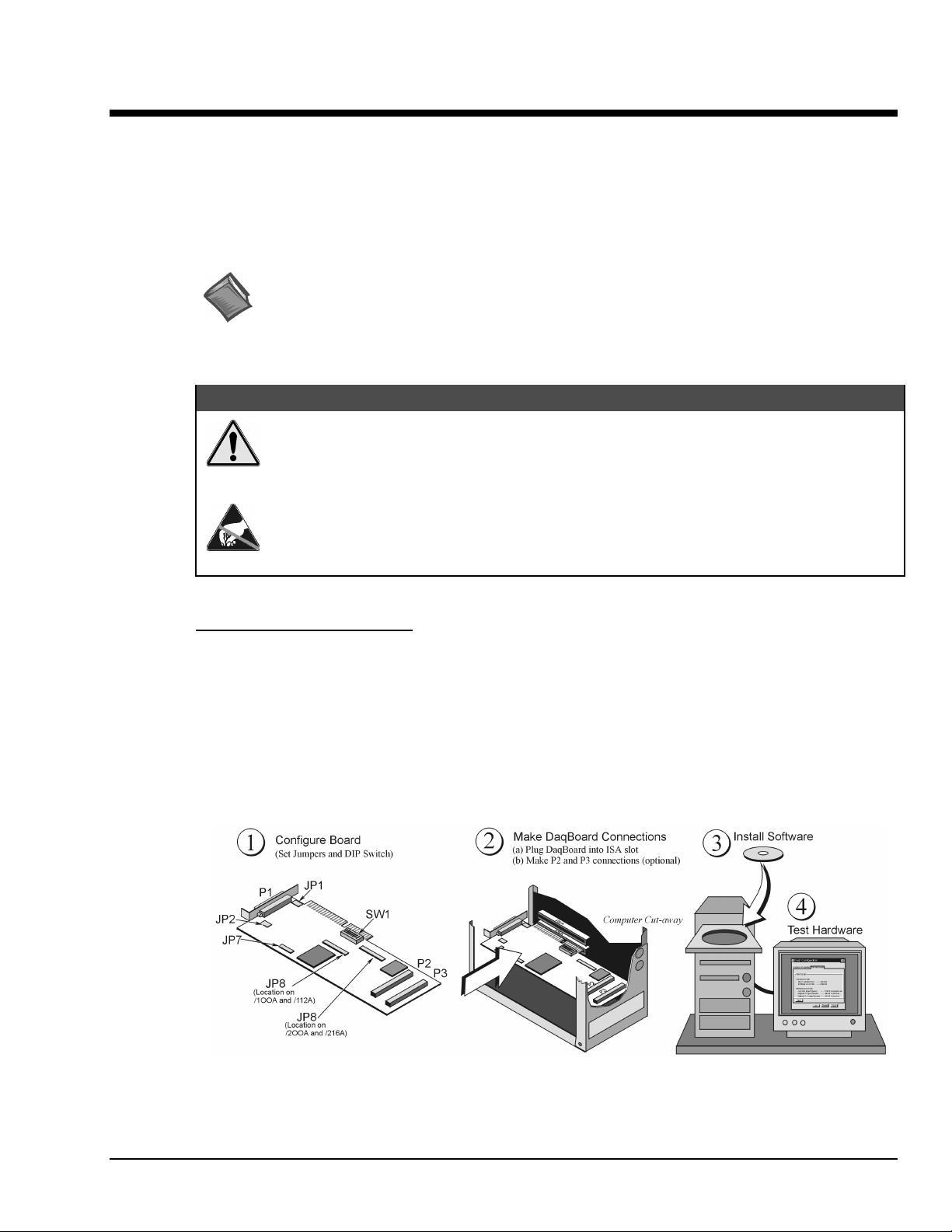
ISA-slot, making board connections, and installing the appropriate software. The figure, provided near the
bottom of this page, provides an overview of the steps necessary for a successful setup.
Reference Note:
The DBK Option Cards and Modules User’s Manual (p/n OMB-457-0905) contains detailed DBK
and power-related information. As a part of product support, the DBK manual is automatically
loaded onto your hard drive during software installation. The default location is the Programs
directory, which can be accessed through the Windows Desktop.
&$87,21
Turn off power to the host PC and externally connected equipment prior to removing the
PC’s cover and installing a DaqBoard. Electric shock or damage to equipment can result
even under low-voltage conditions.
Take ESD precautions (packaging, proper handling, grounded wrist strap, etc.) Use care to
avoid touching board surfaces and onboard components. Only handle boards by their edges
(or ORBs, if applicable). Ensure boards do not come into contact with foreign elements such
as oils, water, and industrial particulate.
Minimum System Requirements
PC system with Pentium® Processor
Windows Operating System
RAM, as follows:
16 Mbytes of RAM for Windows 3.x
32 Mbytes of RAM for Windows 95/98/NT
64 Mbytes of RAM for Windows Me
64 Mbytes of RAM for Windows 2000
64 Mbytes of RAM for Windows XP
DaqBoard-ISA Installation Steps, Pictorial Overview
OMB-DaqBoard-ISA User’s Manual
02-10-02
Setup and Startup 2-1
Page 14
(1) Configure the ISA-DaqBoard
JP1 - External Analog Expansion Power
Placing the jumpers on JP1’s OCTOUT and –OCLKIN could damage the 8254 timer
chip! If either a DBK32A Auxiliary Power Supply or a DBK33 Triple-Output Power
Supply Card is used, the JP1 shunt jumpers must be removed, otherwise timer chip
damage will occur. Refer to the DBK32A, DBK33, and Power Management sections of
the user documentation for more information.
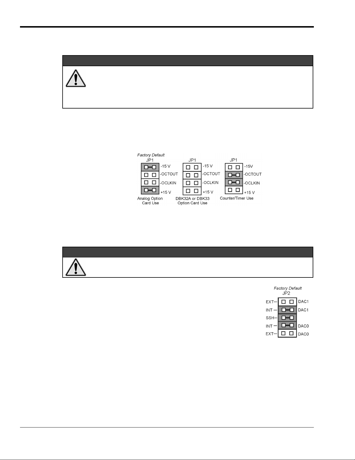
If analog option cards (DBKs) are used, JP1 jumpers are set to provide +15 and -15 VDC to the cards.
If using a DBK32A or DBK33 Power Supply Card, remove all jumpers from JP1.
If no cards are being used, the counter/timer CTR0 is available, and JP1 must be set as shown in the figure.
(Set Jumpers and Configure the DIP-Switch)
&$87,21
JP1 Configurations
JP2 - DAC Reference Voltage and SSH (Simultaneous Sample and Hold)
&$87,21
In regard to JP2, the SSH jumper must be removed if you are using EXT DAC0 or EXT
DAC1. See the user’s manual for details.
JP2 selects an Internal (default) or External reference voltage for the two separate
analog outputs.
JP2 also selects SSH (default) for applications using one or more of the following:
DBK2, DBK4, DBK5, DBK7, DBK17, DBK50, or DBK51.
We recommend that you leave the JP2 jumpers at their factory default setting
(see figure at right). Refer to the JP2 material in chapter 3 prior to making
changes.
JP7 – Calibration
Leave JP7 in the default position. Only use JP7 during calibration.
2-2 Setup and Startup
02-10-02
OMB-DaqBoard-ISA User’s Manual
Page 15

JP8 – DMA and Interrupt
Interrupt Selection. ISA-type DaqBoards may be set to interrupt the PC when certain
hardware conditions occur. The interrupt may be set to IRQ level 10, 11, 12, 14 or 15.
DaqBoard’s IRQ level cannot be shared with another device. To disable interrupt assistance
and background transfers you can configure JP8 to “Open Interrupt.” See the “Open
Interrupt” setting in the following figure.
DMA Selection. Direct Memory Access (DMA) configuration provides for:
Note: Only DMA channels 5-7 (of an ISA AT machine’s seven channels) are
Set DRQ and DACK jumpers to the desired DMA channels. Note that DaqBoard does not
share DMA channels.
Set the DMA jumpers to OPEN when other devices will be using DMA channels 5, 6 and 7.
(a) high-speed data transfer from the ADC FIFO, or
(b) high-speed data transfer to the DAC FIFO.
available to DaqBoard.
SW1 - Base Address
SW1’s factory default is 300 Hex. If 300 Hex presents an address conflict, set a new SW1 address within
the range of 1FF to 3FF (256 to 1023 Decimal). Note that the address must be on a 4-byte boundary.
Industry Standard I/O Addresses
Hex Range Device Hex Range Device
000-1FF Internal system 368-36B PC network (high address)
200-207 Game I/O 36C-36F Reserved
20C-20D Reserved 378-37F Parallel printer port 1
21F Reserved 380-38F SDLC, bisynchronous 2
278-27F Parallel printer port 2 390-393 Reserved
2B0-2DF Alternate enhanced graphics adapter 3A0-3AF Bisynchronous 1
2E1 GPIB (Adapter 0) 3B0-3BF Monochrome display and printer adapter
2E2 & 2E3 Data acquisition (Adapter 0) 3C0-3CF Enhanced graphics adapter
2F8-2FF Serial port 2 3D0-3DF Color/Graphics monitor adapter
300-31F Prototype card 3F0-3F7 Diskette Controller
360-363 PC network (low address) 3F8-3FF Serial port 1
364-367 Reserved
Notes:
(1) SW1’s address must be unique, i.e., not used by another device.
(2) I/O addresses, hex 000 to 0FF, are reserved for system board I/O.
(3) Hex 100 to 3FF are available on the I/O channel.
(4) Although the above table represents industry standards, some systems may vary.
OMB-DaqBoard-ISA User’s Manual
02-10-02
Setup and Startup 2-3
Page 16

(2) Make ISA-DaqBoard Connections
Before connecting your ISA-type DaqBoard, you should review the following connector descriptions.
P1 Analog I/O. Provides 16 analog input channels, 2 analog output channels, a 16-bit counter/timer,
four TTL inputs and outputs, and various signals for driving expansion cards.
P2 Digital I/O. Provides three 8-bit TTL programmable I/O ports and external interrupt input. To ensure
reliable operation, for P2 expansion cables do not exceed 14 inches per attached DBK card.
P3 Frequency I/O. Provides five 16-bit counters and 16 high-speed digital inputs and external interrupt
input.
(a) Turn power OFF to the PC and all attached equipment.
(b) Remove the PC’s cover. Refer to your PC Owner’s
Manual as needed.
(c) Choose an empty 16-bit ISA slot. Loosen and remove the
screw at the top of the slot’s blank adapter plate. Then
slide the plate up and out to remove. Refer to your PC
Owner’s Manual as needed.
(d) Align DaqBoard’s edge-connector with the desired ISA
slot, and with the PC’s corresponding rear-panel slot.
Gently press the board into the ISA slot.
(e) Secure the board by inserting the rear-panel adapter-plate
screw.
(f) If using P2, P3, or both, connect CA-60 cables to the
appropriate on-board P2 and/or P3 headers (see figure).
Secure the P2 and P3 panel connectors to the computer’s
back panel, as applicable.
(g) Replace the computer’s cover. Plug in all cords and
cables; then apply power to the PC.
DaqBoard’s I/O Connectors
If used, P2 and P3 require cable CA-60.
(3) Install Software and Product Support Documentation
Data Acquisition Software, Master Setup Screen
(a) Remove previous version Daq device drivers, if present. You can do this through Microsoft’s
Add/Remove Programs feature by navigating from your desktop as follows:
Start ⇒ Settings ⇒ Control Panel ⇒ Add/Remove Programs
(b) Place the Data Acquisition CD into the CD-ROM drive. Wait for PC to auto-start the CD. This may
take a few moments, depending on your PC. If the CD does not auto-start, use the Desktop’s Start,
Run, Browse feature.
(c) If a Licensing Agreement appears, read over the agreement, then click “Agree.” The Data Acquisition
Software Master Setup Screen appears (see previous figure).
2-4 Setup and Startup
02-10-02
OMB-DaqBoard-ISA User’s Manual
Page 17

(d) Select DaqBook/DaqBoard Support. For Windows95/98/Me/NT/2000/XP, select 32-bit.
If using Windows3.1, or DOS, select 16-bit instead of 32-bit.
(e) If you do not have Acrobat Reader version 4.0 or greater installed on your PC, select Acrobat
Reader. This will enable you to read and print documentation that is included on the install CD-ROM.
Note that PDF versions of the documents are automatically installed onto your hard drive. The default
location is the Programs directory. It can be accessed from the Windows Desktop via the Start button.
(f) Select Post Acquisition Data Analysis Program. Refer to the Post Acquisition Data Analysis
Program document module (e.g. DIAdem, PostView, eZ-View) for information. A copy of the
applicable document module is included in this manual.
(g) Click “Start Install” and follow the screen prompts.
(4) Test Hardware
Use the following steps to test your ISA-type DaqBoard.
(a) Run the Daq Configuration control panel applet.
(b) Click “Add Device.”
(c) Select your DaqBoard model from the “Device Type” scroll box
and click OK.
(d) Select your DaqBoard from the “Device Inventory” window and
click “Properties.”
(e) Ensure settings are correct, and make changes if needed.
(f) Select the “Test Hardware” tab.
(g) Click the “Resource Test” button.
(h) Click the “Test” button.
Test results should be displayed within a few seconds. Note that test
results have two components: Resource Tests and Performance
Tests.
Note: Testing the DaqBoard device may, in some cases, cause the
system to hang. If test results are not displayed in 30 seconds
or the system does not seem to be responding, reboot the
system. Upon power-up, re-enter the Daq Configuration and
change DaqBoard configuration settings to those that work
properly.
Resource Tests
The resource tests are intended to test system capability for the current
device configuration. These tests are pass/fail.
Resource test failure may indicate a lack of availability of the resource
or a possible resource conflict.
•
Base Address Test - Tests the base address for the selected
ISA bus. Failure of this test may indicate that the bus is not
properly configured within the system. See relevant operating
system and computer manufacturer’s documentation to correct
the problem.
•
Interrupt Level Test - Tests the ability of the ISA bus to
generate interrupts. Failure of this test may indicate that the
ISA bus may be currently unable to generate the necessary
hardware interrupt.
Device Inventory and
Device Type Windows
DaqBoard Properties Tab
OMB-DaqBoard-ISA User’s Manual
02-10-02
Setup and Startup 2-5
Page 18

Performance Tests
Performance tests check various DaqBoard functions with the current
device configuration. These tests give quantitative results for each
supported functional group. The results represent maximum rates at
which the various operations can be performed. Note that the rates
depend on selected ISA protocol and will vary according to bus
hardware capabilities.
•
ADC FIFO Input Speed - Tests the maximum rate at which
data can be transferred from the DaqBoard’s internal ADC
FIFO to computer memory, through the PC’s ISA bus.
Results are given in samples/second, where a sample (2 bytes
in length) represents a single A/D value.
•
Digital I/O Input Speed - Tests the maximum rate at which
DIO input data can be transferred from DaqBoard’s Digital
I/O ports to computer memory, through the PC’s ISA bus
slot. Results are given in bytes/second.
•
Digital I/O Output Speed – Tests the maximum rate at which
DIO output data can be transferred from the computer’s
memory to DaqBoard’s Digital I/O ports, through the PC’s
ISA bus slot. Results are given in bytes/second.
Test Hardware Tab
Test Results
Reference Note:
If you experience difficulties, please consult other sections of this manual and to the additional user
documentation before calling technical support. User documentation is included on your data acquisition CD, and is
installed automatically as a part of product support, when your software is installed. The default location is in the
Programs
directory.
Note that hardcopy versions of the manuals can be ordered from the factory.
2-6 Setup and Startup
02-10-02
OMB-DaqBoard-ISA User’s Manual
Page 19

A Closer Look at DaqBoard-ISA Hardware 3
Applies to DaqBoard/100A, /112A, /200A, and /216A
Overview …… 3-1
Performance Factors …… 3- 1
Switches and Jumpers …… 3- 3
Base Address (SW1) …… 3- 3
…… 3-
4
…… 3-
7
8
4
5
…… 3-
9
Overview
External Analog Expansion Power (JP1)
DAC Reference Selection (JP2)
DMA and Interrupt Selection (JP8)
…… 3-
Connections …… 3- 5
P1, DB37 Pinout, Analog I/O
P2, DB37 Pinout, Digital I/O
P3, DB37 Pinout, Pulse/Frequency/High-Speed Digital I/O
…… 3-
…… 3-
The DaqBoard/100A, /112A, /200A, and /216A are 100 kHz ISA-bus plug-in boards that provide analogto-digital conversion with a wide selection of signal-conditioning, signal expansion, and software support.
ISA-DaqBoards feature an on-board 512-location sequencer that lets you select any channel and gain
combination and configure each channel for unipolar or bipolar operation.
Analog input capabilities are flexible. The A/D maximum sample rate is 100 kHz (divide by number of
channels for scan rate) with a 16-channel multiplexer and a programmable-gain input amplifier. Users can
expand channel capacity to 256 analog inputs via expansion modules for multiplexing RTDs,
thermocouples, strain gages, anti-aliasing filters, and simultaneous sample and hold amplifiers. Expansion
cards and modules attach to the P1 I/O connector. Refer to the Connections section beginning on
page 3-5. The P1 DB37 interface is compatible with multiplexers and signal conditioners from several
manufacturers.
Input power for the DaqBoard comes from the host computer’s bus. Output power from the P1 connector
includes +5 VDC (pin 1) and ±15 VDC (pins 21 and 2). The section beginning on page 3-4 entitled,
External Analog Expansion Power (JP1), explains how to set JP1 based on power use in the system.
Related information is included in the Power Management section of the DBK Option Cards and Modules
User’s Manual (p/n OMB-457-0905).
Each ISA-DaqBoard provides 16 analog inputs (expandable up to 256), 2 analog outputs, and 4 digital
inputs and outputs. DaqBoard/100A and DaqBoard/200A have additional digital I/O and counter/timer
capabilities. The various DaqBoard models have either 12-bit or 16-bit resolution. 12-bit models include
DaqBoard/100A and DaqBoard/112A. 16-bit models include DaqBoard/200A and DaqBoard/216A.
Performance Factors
The DaqBoard performs 100 kHz scan sequences and provides programmable delays from 10 µs to
12 hours. The unit’s 100 kHz conversion rate fixes the time skew between channels at 10 µs. The
512-location scan sequencer allows selection of the input amplifier gain for each channel. The
DaqBoard/100A and DaqBoard/200A can scan 16 digital inputs in the same sequence used for analog
inputs (such inputs are thus time-correlated). Optional simultaneous-sample-and-hold (SSH) cards enable
ISA-DaqBoards to sample up to 256 channels at the same instant. Scanning and timing specifications are
met even with a full complement of expansion modules. All types of transducers are scanned within the
same scan group without PC intervention.
ISA-type DaqBoards offer a wide selection of triggering capabilities. The scan can be triggered by
software, a TTL signal, or an analog input level (including slope). The trigger is hardware-based to
minimize trigger latency to less than 10 µs.
Two data transfer modes are supported:
•
•
Real-time data can be collected at 100 K readings/s.
OMB-DaqBoard-ISA User’s Manual
DMA
Fast I/O to data memory via block move instruction REP INSW.
02-14-02
Hardware 3-1
Page 20

This following block diagram can be applied to DaqBoard-ISA models /100A, /112A, /200A, and /216A.
B
Signal
I/O
P1
ANALOG I/O
(DAS-16
compatible)
P2*
DIGITAL I/O
(PIO-12
compatible)
P3*
PULSE/FREQ.
HIGH-SPEED
DIGITAL I/O
(CT M-05
compatible)
*Models /100A and /200A.
8 DE/16 SE
analog input
multiplexer
4 digital outputs
for high-speed
channel expansion
4 general purpose
digital outputs
4 general purpose
digital inputs
1 auxiliary counter gate
1 TTL trigger input
2 gain select outputs for
expansion boards
Dual-DAC
Dual 12-bit
digital-toanalog
converter
24-bit general purpose
digital I/O lines
An optional adapter cable (CA-60) is
}
required for external access to 40-pin
ports P2 and P3 (located on DaqBoards).
16 high-speed
digital inputs
5 counter/timer
channels
Block Diagram for DaqBoard Models /100A, /112A. /200A, /216A
lock Diagram for DaqBoard Models /100A, 112A, 200A, and 216A
-or-
-or-
External
control
MUX
Analog Trigger-In
Com parator
4K - word FIFO
Data Buffer
PGA
x1, x2
x4, x8
per channel
512-step
random access
channel/gain
sequencer
Trigger
Select
Am plifier
Sample
&
Hold
Sequencer
rese t
Programmable
sequencer
tim eba se .
10 us to 12 hrs
12 or 16-bit,
100 kHz
analog-to-digital
converter
100 kHz
Clock
ADC
4K word
FIFO
data
buffer
PC (ISA)
Bus
Interface
DMA &
Interrup t
Interface
+15
-15
& address bus
DC-DC
converter
P C (ISA ) B u s
16-bit data
PC +5V
Power Supply
3-2 Hardware
02-14-02
OMB-DaqBoard-ISA User’s Manual
Page 21

Switches and Jumpers
y
To ensure that the desired mode of operation is obtained, the ISA-type DaqBoards must be configured.
This is accomplished via on-board jumpers and a DIP-switch. Although the configuration of all four
DaqBoard-ISA models is similar, jumper locations differ, as can be seen in the following figures.
DaqBoard/100A/112A Motherboard
The following DIP-switch and jumpers must be properly set to ensure the desired mode of operation:
•
•
•
•
•
Base Address (SW1)
The computer must know the DaqBoard’s base address. Check the base address setting (3-digit hex) on
SW1, the Base Address switch. The factory default is 300 hex (within the standard range for a prototype
card; see table). If the default value does not work, you must select an address within 200 to 3FF (256 to
1023 decimal). In addition, the address must be on a 4-byte boundary, and it must not conflict with
addresses already in use.
JP7
JP2
JP8
SW1
0
1
Base Address
JP1
Location of DaqBoard Jumpers
SW1 - Base Address
JP1 - External Analog Expansion Power
JP2 - DAC Voltage Reference Header
JP7 –Reserved for factory use.
JP8 - Interrupt & DMA
JP7
SW1
0
JP8
DaqBoard/200A/216A Motherboard
1
Base Address
JP2
JP1
Industry Standard I/O Addresses
: Systems vary. This is only a guide.
Note
Hex Range Device
000-1FF Internal system
200-207 Game I/O
20C-20D Reserved
21F Reserved
278-27F Parallel printer port 2
2B0-2DF Alternate enhanced graphics adapter
2E1 GPIB (Adapter 0)
2E2 & 2E3 Data acquisition (Adapter 0)
2F8-2FF Serial port 2
300-31F Prototype card
360-363 PC network (low address)
364-367 Reserved
368-36B PC network (high address)
36C-36F Reserved
378-37F Parallel printer port 1
380-38F SDLC, bisynchronous 2
390-393 Reserved
3A0-3AF Bisynchronous 1
3B0-3BF Monochrome display and printer adapter
3C0-3CF Enhanced graphics adapter
3D0-3DF Color/Graphics monitor adapter
3F0-3F7 Diskette Controller
3F8-3FF Serial port 1
: I/O addresses, hex 000 to 0FF, are reserved for
Note
the system board I/O. Hex 100 to 3FF are available on
the I/O channel.
A2 A3 A4 A5 A6 A7 A8 A9
300
Factor
Default
OPEN
A2 A3 A4 A5 A6 A7 A8 A9
304
OPEN
A2 A3 A4 A5 A6 A7 A8 A9
2 3 14
308
OPEN
A2 A3 A4 A5 A6 A7 A8 A9
30C
OPEN
A2 A3 A4 A5 A6 A7 A8 A9
2 3 14
310
OPEN
Sample Base Addresses
on SW1
6 7 8 5 2 3 14
0
1
6 7 8 5 2 3 14
0
1
6 7 8 5
0
1
6 7 8 5 2 3 14
0
1
6 7 8 5
0
1
OMB-DaqBoard-ISA User’s Manual
02-14-02
Hardware 3-3
Page 22

External Analog Expansion Power (JP1)
Def
The JP1 4×2 header has 3 possible settings.
If analog option cards (DBKs) are used, the
JP1 pins are set to provide ±15 VDC to the
cards. If such cards are not used, the
counter/timer CTR0 is available, and JP1
must be set accordingly. The default
setting is for use of analog option cards.
If using a DBK32A Auxiliary Power Supply or a DBK33 Triple-Output Power
Supply Card, the JP1 shunt jumpers must be entirely removed. Placing the
jumpers on -OCTOUT and -OCLKIN will damage the 8254 timer chip.
Reference Note:
Refer to the Power Management section of the DBK Option Cards and Modules User’s
Manual (p/n OMB- 457-0905), as needed.
DAC Reference Selection (JP2)
The JP2 5×2 header allows you to select internal or external voltage references for the two separate analog
outputs. If the internal -5 VDC reference is selected, either DAC can output from 0 to +5 VDC as the
register count varies from 0 to 4095 (12-bit). If an external voltage reference is desired (up to 10 VDC in
either polarity), the shunt jumpers must be set accordingly. There is also a provision to allow the outputting
of a simultaneous Sample-Hold command signal on the DAC1-REFIN pin with the DAC1 set up for an
internal reference.
JP1
-15V
-OCTO UT
-OCLKIN
+15 V
Co unter/Tim er Use
(16-bit mode only)
JP1 External Analog Expansion Settings
&$87,21
Factory
ault
JP1
-15 V
-OCTO UT
-OCLKIN
+15 V
Analog Option
Card Use
JP1
-15 V
-OCTO UT
-OCLKIN
+15 V
DBK32A or DBK33
Option Card Use
JP2
EXT
INT
SSH
IN T
EXT
DAC0 External Ref
DAC1 External Ref
Reference Note:
The SSH setting is used with DBKs: 2, 4, 5, 7, 17, 50, and 51. In regard to specific DBK
information, refer to the DBK Option Cards and Modules User’s Manual
(p/n OMB-457-0905), as needed.
DAC1
DAC0
DAC0 External Ref
DAC1 Internal Ref
&$87,21
The SSH setting cannot be used at the same time as a DAC1 external reference due
to a potentially damaging conflict on P1 pin #26. The defaults are both DAC0 and
DAC1 set to Internal Reference.
JP2 JP2 JP2
DAC0 Internal Ref
DAC1 External Ref
DAC0 Internal Ref
DAC1 Internal Ref
JP2 DAC Reference Settings
Factory Default
JP2
DAC0 Internal Ref
DAC1 Internal Ref
with S S H
JP2
DAC0 External Ref
DAC1 Internal Ref
with S S H
3-4 Hardware
02-14-02
OMB-DaqBoard-ISA User’s Manual
Page 23

DMA and Interrupt Selection (JP8)
The JP8 11×2 header determines both the interrupt IRQ level and the Direct Memory Access (DMA)
channel for control of background data transfers. The preset default is for DMA channel 5 and for
Interrupt 10 (see figure).
•
Interrupt Selection. The DaqBoard may be set to interrupt the PC when certain hardware conditions
occur. The main board interrupt may be set to IRQ level 10, 11, 12, 14 or 15. The DaqBoard’s IRQ
level cannot be shared with any other device. Setting the JP8 interrupt jumper to OPEN can disable
interrupt assistance and background transfers.
•
DMA Selection. Direct Memory Access allows high-speed data transfer either from the ADC FIFO
or to the DAC FIFO. Only DMA channels 5, 6, and 7 (of an ISA AT machine’s seven channels) are
available for the DaqBoard. Set both the DRQ and DACK jumpers to the desired DMA channel (the
DaqBoard does not share DMA channels). Set the DMA jumpers to OPEN when other devices use
DMA channels 5, 6 and 7.
Factory D efault
DRQ7
DRQ6
DRQ5
IRQ15
DACK7
21
22
DM A Channel 5 and Interrupt 10
DRQ7
DACK6
DRQ6
DACK7
DACK6
Open In ter rup t
DRQ5
IRQ14
DACK5
IRQ 15
IRQ 14
DACK5
IRQ12
IRQ11
IRQ10
1
JP8
2
IRQ 12
IRQ 11
IRQ 10
1
DRQ7
DRQ6
DRQ5
DRQ5
IRQ15
DACK5
IRQ15
DACK5
DACK7
21
22
DM A Channel 7 and Interrupt 12
DRQ7
2121
DACK6
DRQ6
DACK7
DACK6
IRQ14
IRQ12
IRQ11IRQ11
IRQ10
1
JP8
2
IRQ14
IRQ12
IRQ10
1
JP8JP8
2222
Open DMA
22
Connections
Expansion cards connect to the ISA-type DaqBoards via one externally accessible P1 DB37 I/O connector,
or by two on-board 40-pin headers [for P2 and P3 connections] on the DaqBoard/100A and the
DaqBoard/200A. The DBK option cards can be used without an enclosure, or can be installed in a multicard enclosure such as the DBK10, DBK41, or DBK60. The multi-card enclosures can be stacked, making
it possible for a system to accommodate a large number of cards.
JP8 DaqBoard DMA and Interrupt Selection
Reference Notes:
➣
This section pertains to connections and pinouts for ISA-type DaqBoard applications.
➣
For installation instructions, refer to chapter 2, Setup and Startup.
DaqBoard [ISA type] Multi-Card Cabling
OMB-DaqBoard-ISA User’s Manual
02-14-02
Hardware 3-5
Page 24

The P1 connector on the DaqBoard and on each DBK is a DB37 male connector. Connecting DBKs to a
DaqBoard is accomplished with a CA-131-x cable, where the x is the number of option cards to be
connected; for example, a CA-131-3 cable would be used to attach three DBK option cards to a DaqBoard.
Such connections are often referred to as a “daisy-chain.” Note that the CA-131-x cables consist of female
DB37 connectors.
&$87,21
Before connecting DBKs to the DaqBoard, power-down all connected units.
Failure to do so could result in damage to the DBK or DaqBoard.
&$87,21
Do not confuse connectors. Ensure that you only connect P1 I/Os to P1,
P2 I/Os to P2, and P3 I/Os to P3. Improper connection may result in equipment
damage.
In addition to P1 ports, DaqBoard/100A and DaqBoard/200A devices have P2 and P3 ports. For these
devices a CA-60 cable is required to connect the DaqBoard 40-pin headers with a DB37 connector outside
the PC, and then to the DBK option card.
A DaqBoard with CA-60 Cables for P2 and P3
•
P1 Analog I/O. Provides sixteen analog input channels, two analog output channels, a 16-bit
counter/timer, four TTL inputs and outputs, and various signals for driving expansion cards.
•
P2 Digital I/O. Provides three 8-bit TTL programmable I/O ports and external interrupt
input.
P2 expansion cables must be kept relatively short to ensure reliable operation. Do not
exceed 14 inches per attached DBK card.
•
P3 Frequency I/O. Provides five16-bit counters and sixteen high-speed digital inputs and
external interrupt input.
To gain access to the DaqBoard port connectors, signals can be connected via CA-131-x cable through a
D-shell 37-pin female connector or a DBK11 screw-terminal option card with component sockets.
Reference Notes: You must set up DaqView for the particular DBKs in your system. If you
are unfamiliar with the method of setting up DBKs in DaqView, or if you need a refresher,
refer to one or more of the following:
➣
the DaqView document module
➣
the DBK Set Up in DaqView chapter of the DBK Option Cards and Modules User’s
Manual.
➣
The DBK document modules, for hardware configuration aspects that require setup in
software.
3-6 Hardware
Note: As new DBKs become available, be sure to use the latest revision of DaqView with the proper
configuration options.
02-14-02
OMB-DaqBoard-ISA User’s Manual
Page 25

DB37 Pinout Analog I/O Connections for ISA-Type DaqBoards
P1,
N
N
N
N
N
I
I
I
I
N
I
C
D
V
5
1
-
/
T
3
1
U
R
S
S
O
H
H
W
0
C
C
P
/
/
R
V
T
5
+
C
1
2
1
0
2
2
2
C
T
S
D
U
V
H
O
5
C
1
/
/
2
+
/
0
2
N
R
I
P
P
T
0
0
K
C
C
C
/
O
2
L
P
C
I
0
R
T
C
G
/
1
3
3
P
P
P
I
O
O
6
5
3
4
2
4
3
2
2
2
0
0
E
S
T
G
A
I
H
E
R
G
C
R
T
/
0
1
0
R
P
A
I
T
/
D
/
H
S
S
D
N
)
T
V
G
5
U
-
0
1
R
(
O
S
S
/
1
P
I
7
5
2
N
I
F
A
/
D
E
F
0
G
W
A
E
/
A
O
/
R
D
P
V
D
0
1
8
9
1
1
9
8
7
6
2
U
O
1
L
3
2
2
2
T
N
D
D
I
N
N
I
H
G
H
G
6
L
7
L
L
H
H
C
C
I
H
H
4
5
1
1
H
N
H
I
C
C
*
*
C
/
/
*
F
/
N
N
I
I
E
N
I
R
O
O
0
L
7
H
C
2
1
0
3
N
I
I
H
5
H
C
O
O
L
L
L
5
4
6
H
H
H
C
C
C
C
3
4
5
1
1
1
3
1
4
2
3
3
3
N
N
N
I
I
I
I
I
I
I
H
H
H
4
3
2
H
H
H
C
C
C
C
I
I
H
3
1
H
C
*
/
N
I
L
3
H
6
1
5
3
N
I
H
1
H
C
N
I
H
2
1
H
C
*
/
N
I
O
O
L
2
H
C
C
7
1
6
3
N
I
I
H
0
H
N
I
I
I
I
I
I
I
H
H
H
H
0
1
1
H
H
C
*
/
N
I
O
L
1
H
H
C
8
1
7
3
N
I
I
D
8
1
9
N
H
H
G
C
C
*
*
/
/
E
N
N
I
I
S
N
O
E
L
S
0
L
L
9
1
Pin Signal Name Description for P1 Pin Use
1+5 PWR
2 CTR 0 OUT/-15 VDC
+5 V supply (Refer to
Counter 0 output (8254 chip)/ -15 V supply (Refer to
Power Management
, in the DBK manual).
Power Management
, in the DBK manual).
3 OP 3/CHS 3 Digital out bit 3/channel select line for expansion cards
4 OP 1/CHS 1 Digital out bit 1/channel select line for expansion cards
5 IP 3/GS 1 Digital in bit 3/gain select line for expansion cards
6 IP 1/GS 0 Digital in bit 1/gain select line for expansion cards
7 POWER GND Digital ground
8 VREF (-5V) -5 V supply @ 10 mA max
9 D/A 0 OUT Digital to analog converter output ch 0
10 D/A 0 REF IN Digital to analog converter reference in ch 0 (must invert)
11 CH 7 LO IN/CH 15 HI IN Ch 7 LO IN (differential mode)/ch 15 HI IN (single-ended mode)
12 CH 6 LO IN/CH 14 HI IN Ch 6 LO IN (differential mode)/ch 14 HI IN (single-ended mode)
13 CH 5 LO IN/CH 13 HI IN Ch 5 LO IN (differential mode)/ch 13 HI IN (single-ended mode)
14 CH 4 LO IN/CH 12 HI IN Ch 4 LO IN (differential mode)/ch 12 HI IN (single-ended mode)
15 CH 3 LO IN/CH 11 HI IN Ch 3 LO IN (differential mode)/ch 11 HI IN (single-ended mode)
16 CH 2 LO IN/CH 10 HI IN Ch 2 LO IN (differential mode)/ch 10 HI IN (single-ended mode)
17 CH 1 LO IN/CH 9 HI IN Ch 1 LO IN (differential mode)/ch 9 HI IN(single-ended mode)
18 CH 0 LO IN/CH 8 HI IN Ch 0 LO IN (differential mode)/ch 8 HI IN (single-ended mode)
19 L.L. GND Low-level ground (analog ground - use with analog inputs and outputs)
20 CTR 2 OUT Counter 2 output (8254 chip)
21 CTR 0 CLOCK IN/+15 VDC
Counter 0 clock in (8254 chip)/+15 V supply (Refer to
Power Management
, in the DBK
manual).
22 OP 2/CHS 2 Digital output bit 2/ channel select line for expansion cards
23 OP 0/CHS 0 Digital output bit 0/channel select line for expansion cards
24 IP 2/CTR 0 GATE Digital input bit 2/counter 0 gate (16-bit support only)
25 IP 0/TRIG 0 Digital input bit 0/trigger 0
26 D/A 1 REF IN/SSH Digital-to-analog converter reference in ch 1 (must invert)/ SSH
27 D/A 1 OUT Digital-to-analog converter output ch 1
28 L.L. GND Low-level ground (analog ground - use with analog inputs and outputs)
29 L.L. GND Low-level ground (analog ground - use with analog inputs and outputs)
30 CH 7 HI IN Ch 7 HI IN (single-ended mode or differential mode)
31 CH 6 HI IN Ch 6 HI IN (single-ended mode or differential mode)
32 CH 5 HI IN Ch 5 HI IN (single-ended mode or differential mode)
33 CH 4 HI IN Ch 4 HI IN (single-ended mode or differential mode)
34 CH 3 HI IN Ch 3 HI IN (single-ended mode or differential mode)
35 CH 2 HI IN Ch 2 HI IN (single-ended mode or differential mode)
36 CH 1 HI IN Ch 1 HI IN (single-ended mode or differential mode)
37 CH 0 HI IN Ch 0 HI IN (single-ended mode or differential mode)
Notes
:
(1) Software configuration commands determine P1 digital I/O pin functions.
(2) Actual shunt-jumper placement is required to provide ±15 VDC to expansion cards or disconnect internal DAC references to
allow externally selected DAC references.
(3) Digital I/O is not available with DBKs due to line use for addressing. “/” indicates the pin can be used for either function but not
both at the same time.
(4) DaqBoard [ISA-Type] P1 is compatible with Metrabyte DAS-16.
(5) The pinout is for ISA-type DaqBoards. It does not apply to PCI or cPCI type DaqBoards.
OMB-DaqBoard-ISA User’s Manual
02-14-02
Hardware 3-7
Page 26

DB37 Pinout Digital I/O Connections for ISA-Type DaqBoards
P2,
E
L
6
7
4
5
T
U
P
N
N
E
I
R
R
I
I
P
1
3
2
B
B
B
A
T
T
R
R
O
O
P
P
4
5
B
B
B
T
T
T
R
R
R
R
O
O
O
O
P
P
P
8
6
7
0
2
1
3
B
B
B
T
T
T
R
D
R
/
O
N
O
N
P
G
P
2
0
1
1
1
9
1
D
D
C
G
3
1
C
C
N
/
N
/
N
G
N
6
5
4
7
1
1
1
1
The DaqBoard [ISA-Type] P2
interface is available on:
DaqBoard/100A
3
1
DaqBoard/200A
3
1
2
0
2
2
2
2
6
7
D
V
5
N
C
C
+
G
T
T
T
R
R
R
O
O
O
P
P
P
DB37 Connector via CA-60 Inte rfa ce Cable
6
4
5
2
2
2
2
3
5
2
4
C
C
C
C
T
T
T
T
R
R
R
R
O
O
O
O
P
P
P
P
P
0
9
8
7
3
2
2
6
7
0
1
A
A
C
C
T
T
T
T
R
R
R
R
O
O
O
O
P
P
P
4
2
3
5
A
R
O
P
5
3
3
3
3
1
3
4
2
A
A
A
A
T
T
T
T
T
R
R
R
R
O
O
O
O
P
P
P
P
Pin Signal Name Description for P2 Pin Use
1 IR INPUT Interrupt line input (no functions to access this)
2 IR ENABLE Interrupt line enable (no functions to access this)
3 PORT B 7 Digital input/output - port B bit 7
4 PORT B 6 Digital input/output - port B bit 6
5 PORT B 5 Digital input/output - port B bit 5
6 PORT B 4 Digital input/output - port B bit 4
7 PORT B 3 Digital input/output - port B bit 3
8 PORT B 2 Digital input/output - port B bit 2
9 PORT B 1 Digital input/output - port B bit 1
10 PORT B 0 Digital input/output - port B bit 0
11 GND Digital ground
12 N/C Pin not connected/not used
13 GND Digital ground
14 N/C Pin not connected/not used
15 GND Digital ground
16 N/C Pin not connected/not used
17 GND Digital ground
18 +5 V
+5 V supply (Refer to
Power Management
, in the DBK manual).
19 GND Digital ground
20 +5 V
+5 V supply (Refer to
Power Management,
in the DBK manual).
21 GND Digital ground
22 PORT C 7 Digital input/output - port C bit 7
23 PORT C 6 Digital input/output - port C bit 6
24 PORT C 5 Digital input/output - port C bit 5
25 PORT C 4 Digital input/output - port C bit 4
26 PORT C 3 Digital input/output - port C bit 3
27 PORT C 2 Digital input/output - port C bit 2
28 PORT C 1 Digital input/output - port C bit 1
29 PORT C 0 Digital input/output - port C bit 0
30 PORT A 7 Digital input/output - port A bit 7
31 PORT A 6 Digital input/output - port A bit 6
32 PORT A 5 Digital input/output - port A bit 5
33 PORT A 4 Digital input/output - port A bit 4
34 PORT A 3 Digital input/output - port A bit 3
35 PORT A 2 Digital input/output - port A bit 2
36 PORT A 1 Digital input/output - port A bit 1
37 PORT A 0 Digital input/output - port A bit 0
40
D
D
N
N
5
G
+
G
9
8
1
1
6
7
3
3
0
A
2
The P2 40 -pin header does not
have a direct pin-to-pin correlation
with the P 2 D B 37 conn ec tor.
39
1
Note: No local lines are available if digital expansion cards are in use.
.
P2 expansion cables must be kept relatively short to ensure reliable operation.
Do not exceed 14 inches per attached DBK card.
Note: The pinout is for ISA-type DaqBoards. It does not apply to PCI or cPCI type DaqBoards.
3-8 Hardware
02-14-02
OMB-DaqBoard-ISA User’s Manual
Page 27

, DB37 Pinout Pulse/Frequency/High-Speed Digital I/O for ISA-Type DaqBoards
P3
E
E
T
E
L
T
B
U
A
P
N
5
7
N
I
I
E
D
D
R
R
I
I
S
1
S
2
3
4
3
6
4
I
I
I
I
D
D
D
S
S
S
5
7
8
6
0
I
D
2
I
D
D
S
S
1
9
R
1
I
T
D
N
S
C
G
0
2
3
1
1
1
1
T
A
I
G
5
5
R
T
T
C
C
5
4
1
1
A
A
N
N
I
G
G
4
3
4
R
R
R
R
T
T
T
C
C
C
C
7
8
6
1
1
1
The DaqBoard P3 interface is
available on:
1
2
3
DaqBoard/100A
DaqBoard/200A
7
1
0
2
2
2
2
4
C
V
5
/
1
1
5
I
I
N
+
D
D
D
S
S
S
DB37 Connector via CA-60 Inte rfa ce Cable
6
3
4
2
2
2
3
2
1
1
I
I
D
D
S
S
8
0
5
1
1
I
D
S
9
2
2
2
2
3
0
9
I
1
I
D
S
O
T
8
T
I
U
U
D
O
O
O
S
5
4
C
S
R
R
R
T
T
T
C
C
C
4
7
6
3
3
T
U
O
3
R
T
C
5
3
3
3
3
3
T
T
U
U
O
2
1
R
T
C
T
E
N
I
T
U
1
A
O
G
R
T
1
C
R
T
C
Pin Signal Name Description for P3 Pin Use
1 IR INPUT Interrupt line input (used with counters)
2 IR ENABLE Interrupt line enable (used with counters)
3 SDI 7 High-speed digital input bit 7 (low byte)
4 SDI 6 High-speed digital input bit 6 (low byte)
5 SDI 5 High-speed digital input bit 5 (low byte)
6 SDI 4 High-speed digital input bit 4 (low byte)
7 SDI 3 High-speed digital input bit 3 (low byte)
8 SDI 2 High-speed digital input bit 2 (low byte)
9 SDI 1 High-speed digital input bit 1 (low byte)
10 SDI 0 High-speed digital input bit 0 (low byte)
11 GND Digital ground
12 CTR 5 GATE Counter 5 gate (9513 chip)
13 CTR 5 IN Counter 5 input (9513 chip)
14 CTR 4 GATE Counter 4 gate (9513 chip)
15 CTR 4 IN Counter 4 input (9513 chip)
16 CTR 3 GATE Counter 3 gate (9513 chip)
17 CTR 3 IN Counter 3 input (9513 chip)
18 CTR 2 GATE Counter 2 gate (9513 chip)
19 CTR 2 IN Counter 2 input (9513 chip)
20 +5 V
+5 V supply (Refer to
Power Management,
in the DBK manual).
21 D IN STROBE NC
22 SDI 15 High-speed digital input bit 15 (high byte)
23 SDI 14 High-speed digital input bit 14 (high byte)
24 SDI 13 High-speed digital input bit 13 (high byte)
25 SDI 12 High-speed digital input bit 12 (high byte)
26 SDI 11 High-speed digital input bit 11 (high byte)
27 SDI 10 High-speed digital input bit 10 (high byte)
28 SDI 9 High-speed digital input bit 9 (high byte)
29 SDI 8 High-speed digital input bit 8 (high byte)
30 OSC. OUT Oscillator output - fout (9513 chip)
31 CTR 5 OUT Counter 5 output (9513 chip)
32 CTR 4 OUT Counter 4 output (9513 chip)
33 CTR 3 OUT Counter 3 output (9513 chip)
34 CTR 2 OUT Counter 2 output (9513 chip)
35 CTR 1 OUT Counter 1 output (9513 chip)
36 CTR 1 IN Counter 1 input (9513 chip)
37 CTR 1 GATE Counter 1 gate (9513 chip)
E
T
N
I
A
3
G
R
R
T
T
C
9
1
40
E
T
N
I
2
2
The P3 40 -pin header does not
have a direct pin-to-pin correlation
with the P 3 D B 37 conn ec tor.
39
1
Note: The pinout is for ISA-type DaqBoards. It does not apply to PCI or cPCI type DaqBoards.
OMB-DaqBoard-ISA User’s Manual
02-14-02
Hardware 3-9
Page 28

3-10 Hardware
02-14-02
OMB-DaqBoard-ISA User’s Manual
Page 29

DBK Basics
Introduction…… 1
How Do DBKs Connect to the Data Acquisition Device? …… 2
DBK Identification Tables ….. 3
Analog Output DBKs …… 3
Digital I/O Control DBKs …… 3
Analog Signal Conditioning DBKs …… 3
Expansion and Terminal Panel Connection DBKs …… 4
Power Supply DBKs …… 4
Tips on Setting up a Data Acquisition System …… 4
Power Supplies and Power Connectors ……6
An Introduction to Power-Related DBKs ….. 7
Calculating Your System’s Power Needs …… 9
Additional Reading ….. 11
&$87,21
Introduction
The term “DBK” typically refers to a card or module that is used to expand or enhance a primary data
acquisition device, such as a DaqBook, DaqBoard, or LogBook. As will be seen in the upcoming DBK
identification tables, DBKs provide a wide variety of data acquisition functions. Depending on the DBKs
used, one or more of the following can be realized:
Turn off power to all devices connected to the system before connecting cables or
setting configuration jumpers and switches. Electrical shock or damage to
equipment can result even under low-voltage conditions.
&$87,21
The discharge of static electricity can damage some electronic components.
Semiconductor devices are especially susceptible to ESD damage. You should
always handle components carefully, and you should never touch connector pins or
circuit components unless you are following ESD guidelines in an appropriate ESD
controlled area. Such guidelines include the use of properly grounded mats and
wrist straps, ESD bags and cartons, and related procedures.
•
signal conditioning
•
analog output
•
digital I/O
•
channel expansion
•
supplying powering to another acquisition device
•
providing an interface for different connectivity.
Daq Systems
02-19-02
OMB-DBK Basics, pg. 1
Page 30

Reference Notes: During software installation, Adobe
®
PDF versions of user manuals will
automatically install onto your hard drive as a part of product support. The default location
is in the Programs directory, which can be accessed from the Windows Desktop. Refer to
the PDF documentation, especially the DBK Option Cards and Modules User’s Manual
(p/n OMB-457-0905) for details regarding both hardware and software in relevant to DBKs.
A copy of the Adobe Acrobat Reader
®
is included on your CD. The Acrobat Reader
provides a means of reading and printing the PDF documents. Note that hardcopy versions
of the manuals can be ordered from the factory.
How Do DBKs Connect to the Data Acquisition Device?
Each DBK connects to the primary data acquisition device; e.g., a DaqBook, DaqBoard, or LogBook,
through one of three 37-pin ports, which are designated as follows:
•
P1 – Analog I/O
•
P2 – Digital I/O
•
P3 – Pulse/Frequency/High-Speed Digital I/O
Depending on the primary data acquisition device, connectivity issues differ slightly. This will be made
clear by the figures and accompanying text that follow.
For DaqBooks, ISA-Type DaqBoards, and LogBooks, DBK connections are not made directly to the port,
but through a CA-37-x ribbon cable, where “x” indicates the number of expansion devices that can be
connected. For example, in addition to providing a DB37 connector to interface with the primary data
acquisition device, a CA-37-3 cable includes three additional DB37 connectors. These provide a means of
adding three DBKs to one port. Use of a CA-37-16 cable will allow up to 16 DBKs to be added. The
CA-37-x cable system is excellent for DaqBooks, LogBooks, and ISA-type DaqBoards.
The above figure applies to LogBooks, DaqBooks, and ISA-type DaqBoards. As will be seen elsewhere in
the documentation, some models do not include all three connectors (P1, P2, and P3).
pg. 2, OMB-DBK Basics
Connecting DBKs to a DaqBook
02-19-02
Daq Systems
Page 31

DBK Identification Tables
Analog Output DBKs
Analog Output
Product Name/Description I/O
DBK2 Voltage Output Card 4 channels P1
DBK5 Current Output Card 4 channels P1
Digital I/O Control DBKs
Digital I/O / Control
Product Name/Description I/O
DBK20 General-Purpose Digital I/O Card (Screw Terminals) 48 channels P2
DBK21 General-Purpose Digital I/O Card (DB37 Connectors) 48 channels P2
DBK23 Optically Isolated Digital-Input Module 24 channels P2
DBK24 Optically Isolated Digital-Output Module 24 channels P2
DBK25 Relay Output Card 8 channels P2
Analog Signal Conditioning DBKs
The DBKs that are used for analog signal conditioning attach to transducers and condition their outputs into
analog voltages. An A/D converter, located in the primary acquisition device, measures the analog
voltages. There are many signal-conditioning solutions available (and more are in development). Note that
DBK high-capacity modules require more circuitry than can fit on a compact card.
Analog Signal Conditioning
Product Name/Description I/O
DBK4 Dynamic Signal Input Card 2 channels P1
DBK7 Frequency-to-Voltage Input Card 4 channels P1
DBK8 High-Voltage Input Card 8 channels P1
DBK9 RTD Measurement Card 8 channels P1
DBK12 Low-Gain Analog Multiplexing Card 16 channels P1
DBK13 High-Gain Analog Multiplexing Card 16 channels P1
DBK15 Universal Current/Voltage Input Card 16 channels P1
DBK16 Strain-Gage Measurement Card 2 channels P1
DBK17 Simultaneous Sample & Hold Card 4 channels P1
DBK18 Low-Pass Filter Card 4 channels P1
DBK19 Thermocouple Card 14 channels P1
DBK42 5B Isolated Signal-Conditioning Module 16 channels P1
DBK43A Strain-Gage Measurement Module 8 channels P1
DBK44 5B Isolated Signal-Conditioning Card 2 channels P1
DBK45 SSH and Low-Pass Filter Card 4 channels P1
DBK50 Isolated High-Voltage Input Module 8 channels P1
DBK51 Isolated Low-Voltage Input Module 8 channels P1
DBK52 Thermocouple Input Module 14 channels P1
DBK53 Low-Gain Analog Multiplexing Module 16 channels P1
DBK54 High-Gain Analog Multiplexing Module 16 channels P1
DBK80 Differential Voltage Input Card with Excitation Output 16 channels P1
DBK81 Thermocouple Card, High-Accuracy 7 channels P1
DBK82 Thermocouple Card, High-Accuracy 14 channels P1
DBK83 Thermal Couple Card, High-Accuracy; uses Connection Pod 14 channels POD-1
DBK84 Thermocouple Module, High-Accuracy 14 channels P1
Conectivity
Conectivity
Connectivity
Daq Systems
02-19-02
OMB-DBK Basics, pg. 3
Page 32

Expansion and Terminal Panel Connection DBKs
The following DBKs offer provide various expansion and connection options. The stackable 3-slot DBK10
low-profile enclosure can be used for up to three DBKs. If a system has more than 3 DBKs, the 10-slot
DBK41 can be used. Several DBK41s can be daisy-chained to accommodate many DBKs in one system.
Expansion and Connection, General
Product Name/Description I/O
DBK1 16-Connector BNC Adapter Module 16 connectors P1
DBK10 3-Slot Expansion Chassis 3 cards P1, P2, or P3
DBK11A Screw-Terminal Option Card (DB37-Screw Terminal Block) Component
DBK40 BNC Interface 18 connectors P1 or P3
DBK41 Analog Expansion Enclosure 10 cards P1 or P2
DBK60 Expansion Chassis with Termination Panels 3 cards P2
Termination Panels, Connectivity for DaqBoard/260
Product Name/Description I/O
DBK601 Termination Panel - blank rear panel none none
DBK602 Termination Panel - BNC rear panel 16 connectors BNC
DBK603 Termination Panel - Safety Jacks, single ended 16 connectors Safety Jacks
DBK604 Termination Panel - Safety Jacks, differential 8 differential (16) Safety Jacks
DBK605 Termination Panels - Thermal Couple, differential panels;
specify type: B, J, K, R, S, or T
DBK606 Termination Panel – 3 Terminal Blocks; 16 connections per TB 48 connectors Screw Terminal
DBK607 Termination Panel – strain relief clamp none none
DBK608 Termination Panel – 3 female DB37 connectors three DB37 DB37
Connectivity
P1
sockets
Connectivity
16 differential T/C Connectors
Power Supply DBKs
Power supply type DBKs are typically used in laboratory, automotive, and field applications. Input power
can come from any +10 to +20 VDC source, or from an AC source by using an appropriately rated AC-toDC adapter. The DBK30A rechargeable power supply can power DBK modules where AC mains are not
available (the DBK30A outputs 28 V for powering transducers). For a large number of DBK cards, the
DBK32A or DBK33 can be installed into an expansion slot. The DBK33 is used when +5 V is required in
addition to ±15 VDC. The DBK34 provides a steady 12 or 24 VDC while working with vehicle electrical
systems that may be turned on or off during testing.
Power Supply
Product Name/Description Power
DBK30A Rechargeable Battery/Excitation Module +12-14, 24-28 VDC (3.4 A-hr @ 14 VDC)
DBK32A Auxiliary Power Supply Card ±15 V @ 500 mA
DBK33 Triple-Output Power Supply Card ±15 V @ 250 mA; +5 V @ 1 A
DBK34 Vehicle UPS Module 12/24 VDC (5 A-hr @12 VDC)
DBK34A UPS Battery Module 12/24 VDC (5 A-hr @12 VDC)
Tips on Setting up a Data Acquisition System
A successful installation involves setting up equipment and setting software parameters. In addition to this
manual, you may need to consult your Daq device or LogBook user’s manual.
DBKs should be configured before connections are made and power is applied. This sequence can prevent
equipment damage and will help ensure proper operation on startup. Many DBKs have on-board jumpers
and/or DIP switches that are used for setting channels and other variables. You will need to refer to the
individual DBK document modules to ensure that the DBKs are properly configured for you application.
Prior to designing or setting up a custom data acquisition system, you should review the following tips.
After reviewing the material you can write out the steps to setup a system that will best meet your specific
application needs.
pg. 4, OMB-DBK Basics
02-19-02
Daq Systems
Page 33

1. The end use of the acquisition data should be used to determine how you set up and program your
acquisition system. Prior to creating the system you should understand its layout and know how you
are going to assign the channels. If you can answer the following questions you are off to a good start.
If not, you need to find the answers.
•
What engineering units, ranges, sampling rates, etc. are best for your data?
•
Will the data be charted graphically, statistically processed, or exported to other programs?
•
How will the data be used?
•
How will the data be saved?
•
What are your system’ power requirements? Using several DBKs or transducers that
require excitation current may require an extra power supply, e.g., a DBK32A.
2. Assign channel numbers.
3. Plan the location of transducers, cable runs, DBKs, the acquisition device [LogBook or Daq device],
and the computer. Label your transducers, cables, and connectors to prevent later confusion.
4. When configuring your LogBook or Daq device(s) consider the following:
•
LogBook calibration is typically performed automatically through LogView software;
however, some DBKs may require manual calibration.
•
The DaqBook and DaqBoard (ISA type) have internal jumpers and switches that you
must set manually to match your application.
•
Some DaqBook models are partially configured in software.
•
Daq PC-Cards are configured entirely in software.
•
You may need to refer to other documentation, such as Quick Starts, Installation Guides,
User’s Manuals, and pertinent DBK document modules.
5. Perform all hardware configurations before connecting signal and power. Remember to configure all
the DBK cards and modules for your application. Several jumpers and DIP switches may need to be
set (channel, gain, filters, signal mode, etc).
6. Setting up channel parameters often requires both hardware and software setup.
7. Route and connect all signal and power cables while all power is turned OFF.
8. To minimize electrical noise, route all signal lines away from any RF or high-voltage devices.
9. Follow your device’s specific installation instructions. For certain devices software should be installed
first; for others, hardware should be installed prior to software installation.
10. After software is loaded, remember to set the software parameters as needed for your
application. The software must recognize all the hardware in the system. Measurement units
and ranges should be checked to verify that they meet your application requirements.
11. Remember to set all channels to the proper mode for your DBK or other signal source.
12. After your system is up and running, verify proper data acquisition and data storage.
13. Verify system accuracy; adjust ranges or calibrate as needed.
14. Device specific information regarding system setup and expansion can be found in the Daq and
LogBook User’s manuals; and in the applicable DBK document modules of this manual.
Daq Systems
02-19-02
OMB-DBK Basics, pg. 5
Page 34

If you are considering system expansion, review the DBK10, DBK41, and DBK60 document
15.
modules. The best option depends on the number of DBK cards in your system. For just a few cards,
use the stackable 3-slot DBK10 low-profile expansion enclosure. For more than six cards, use the
10-slot DBK41. DBK41s can be daisy-chained to one-another to handle a large number of DBKs.
In regard to power management, you should review the DBK30A, DBK32A, and DBK33 document
16.
modules. For portable applications, the compact DBK30A rechargeable power supply can provide
power to the DBK10 or DBK41. The DBK30A also includes a 28 V output for powering 4 to 20 mA
transducers. For applications with many DBK cards (initially or in future expansion), the DBK32A or
DBK33 can be installed into any expansion slot. The DBK32A provides ±15 VDC and the DBK33
provides ±15 VDC and +5 VDC.
Power Supplies and Connectors
Power supplies convert the raw power they receive into a lower DC voltage and/or current for use by
devices with various power demands. Many of the power supplies that are used to power data acquisition
equipment are of the switching-mode type. These devices provide a regulated output whether the power
supply’s input is, for example, 60 Hz, 120 VAC as in the United States or, 50 Hz, 220 VAC as found in
European countries. Small power supplies, that do not switch, consist of simple transformer/rectifiers and
filtered capacitors; and operate over a smaller voltage range.
LogBooks - The switching-mode power supply commonly used with LogBook systems uses an input
range of 100 VAC to 240 VAC at 50 Hz to 60 Hz. The power supply’s output [to the LogBook] is
15 VDC @ 2.7 amps via a DIN5 connector.
DaqBooks - Power supplies that are used with DaqBooks are typically of the transformer/rectifier type.
They supply the DaqBook with 15 VDC @ 900 mA via a DIN5 connector.
DBKs – The following table indicates the type of power supply that is typically used with certain DBKs.
15 VDC @ 2700 mA
Switching-Mode
Type Power Supply
The DBKs in this column use up to 15 VDC @
2700 mA. This switching-mode power supply
receives power from a 100 to 240 VAC source,
at 50 to 60 Hz, and converts it to the required value.
15 VDC @ 900 mA
Transformer/Rectifier
Type, Unregulated Power Supply
The DBKs in this column use up to15 VDC @
900 mA. This transformer/rectifier type power
supply receives power from a 110 to 125 VAC
source, at 60 Hz, and converts it to the required
value.
DBK Description DBK Description
DBK32A Auxiliary Power Supply Card DBK23 Optically Isolated Digital-Input Module
DBK33 Triple-Output Power Supply Card DBK24 Optically Isolated Digital-Output Module
DBK42 5B Isolated Signal Conditioning Module DBK43A Strain Gage Measurement Module
DBK50 Isolated High-Voltage Input Module
DBK51 Isolated Low-Voltage Input Module
pg. 6, OMB-DBK Basics
02-19-02
Daq Systems
Page 35

The DIN5 is the system’s basic power connector (see the following figure). The CA-115 is a 6-in. cable
y
y
D
with a plug (male) DIN5 connector on both ends. The CA-115 is used to connect DBK32As [or DBK33s]
in parallel when they are to be powered by the same power supply.
GND
Power output connector (plug)
on power suppl
ends of CA-115 cable
Power input (or dais
connector (socket) on device
powered (DaqBook, DBK32A,
DBK33)
cable and both
-chain)
DIN5 Power Connector
IN5 Power Connectors
+V
GND
+V
Power Out
Power In
Note:
Note:
DIN5 connectors for LogBook, DBK34, and DBK34A have threaded retaining rings.
The following figure shows the pinout for the DBK34 and DBK34A Power Out DIN5
connector. The 28 V pin is only active when the device is in the 28 VDC mode; however,
the 14 V pin is active regardless of the mode selected.
DIN5 Power Out
On a DBK34 and DBK34A
An Introduction to Power-Related DBKs
The power-related DBK options are the DBK30A, DBK32A, DBK33, DBK34, and DBK34A. From the
standpoint of providing reliable power, these DBKs have proven convenient in laboratory, automotive, and
field applications.
Input power for these devices can come from any 10 to 20 VDC source, or from an AC source via an
appropriate AC-to-DC adapter.
A brief synopsis of the DBK power options follows. Refer to the respective document modules for
complete information.
DBK30A
The DBK30A’s 28 V output will power 4 to 20 mA transducers.
module - provides power at 14 and 28 VDC with a rated capacity of 3.4 A-hr @ 14 VDC.
The module’s rechargeable power supply can power
DBK modules in situations where AC mains are not available.
Note: Some transducers (e.g., 2-wire 4-20 mA transmitters, bridge-configured sensors, etc) require an
excitation voltage in order to work properly. The DBK30A supplies 14 and 28 VDC. Consult
transducer documentation before applying power.
Daq Systems
02-19-02
OMB-DBK Basics, pg. 7
Page 36

DBK32A
- provides ±15 VDC @ 500 mA.
DBK33
- provides ±15 VDC @ 250 mA and +5 VDC @ 1000 mA.
The DBK32A and DBK33 power cards attach directly to the P1 analog expansion bus where they supply power
to DBK analog expansion cards. The DBK32A and the DBK33 can be powered from an included AC adapter,
an optional DBK30A battery module, or from a +10 to +20 VDC source such as a car battery.
When installed in a DBK10
three-slot expansion chassis, the DBK32A or DBK33 supplies power to
the analog DBK [that is to receive power] via a CA-37-x cable.
If used with the DBK41
ten-slot expansion enclosure, the DBK32A or DBK33 installs into one of the analog
expansion slots on the DBK41’s backplane. A power card in any DBK41slot (other than the leftmost, when
viewed from the rear) will power the other cards that are connected to the DBK41’s backplane.
&$87,21
If using a DBK32A or a DBK33 with a DaqBook or DaqBoard [ISA type], you must
entirely remove the shunt jumpers from JP1. Failure to do so will result in damage to the
8254 timer chip. Refer to the power card document modules and to the Daq device
Hardware sections of the DaqBook and DaqBoard [ISA] user’s manuals for JP1 location
and configuration.
DBK34
Uninterruptable Power Supply (UPS) that can be used for in-vehicle testing where the vehicle’s electrical
system will not affect acquisition device power during starter-current surge, or power-off.
module – provides 12 or 24 VDC with a 5.0 or 2.5 A-hr capacity (respectively). This module is an
DBK34A
classified as a UPS / Battery module. It is an improved version of the earlier DBK34. Like the DBK34, the
DBK34A can be used for in-vehicle testing where the vehicle’s electrical system will not affect acquisition
device power during power during starter-current surge, or power-off.
pg. 8, OMB-DBK Basics
module – provides 12 or 24 VDC with a 5.0 or 2.5 A-hr capacity (respectively). This device is
02-19-02
Daq Systems
Page 37

Calculating Your System’s Power Needs
Use the chart below and the worktable on the next page to ensure your system will have sufficient power.
If the load (calculated in the worktable) exceeds available power (from the chart at the right), you must
add a power card or a module such as a DBK32A or DBK33.
Available Power Chart—Supply
Product Available Power
LogBook +5 VDC @ 0.10 A from P1-1, P2-18, P2-20, P3-20
+15 VDC @ 0.15 A from P1-21
+15 VDC @ 0.05 A from P3-19
-15 VDC @ 0.15 A from P1-2
-15 VDC @ 0.05 A from P3-37
DaqBook/100 2100 mW
DaqBook/112 2400 mW
DaqBook/120 2100 mW
DaqBook/200 4000 mW
DaqBook/216 4000 mW
DaqBook/260 4000 mW
DaqBoard/100A 3300 mW
DaqBoard/112A 3300 mW
DaqBoard/200A 3000 mW
DaqBoard/216A 3000 mW
DaqBoard/260A 3000 mW
DBK32 7500 mW
DBK32A 15000 mW
DBK33 7500 mW
DBK34 5 A-hr in 12 V mode; fused at 8 A
DBK34A 5 A-hr in 12 V mode; fused at 8 A
Use the following procedure and table to calculate the required system power.
1. In the Quantity column (5th), list the number of DBKs of that type in your system.
2. In the Sub Total column (7th), enter the product of column 5 and column 6 (mW).
3. Add the Sub Total column, and enter the sum at the bottom right of the table.
This result is your power requirement in mW.
DBK32, DBK32A, and DBK34 cannot supply +5 VDC.
In cases that require +5 VDC, if the +5 VDC requirement exceeds 500 mW from a
LogBook or Daq device, then a DBK33 must be used. Note that DBK33 can supply
1000 mW at +5 VDC.
Note:
The DBK34 has an 8 amp fuse, and has a capacity of 5 A-hr when in the 12V mode,
and a capacity of 2.5 A-hr when in the 24V mode.
Daq Systems
02-19-02
OMB-DBK Basics, pg. 9
Page 38

DBK Power Requirement Worktable—Demand
DBK Voltage Reference Calculation
Options +15 VDC -15 VDC +5 VDC Quantity × mW = Sub Total
DBK1
DBK2
DBK4
DBK5
DBK7
DBK8
DBK9
DBK11A
DBK12
DBK13
DBK15
DBK16
DBK17
DBK18
DBK19
DBK20
DBK21
DBK23***
DBK24***
DBK25
DBK40
DBK41
DBK42
DBK43A***
DBK44
DBK45
DBK50***
DBK51***
DBK52
DBK53
DBK54
DBK80
DBK81
DBK82
DBK83
DBK84
: DBK44’s 60 mA value is based on 30 mA for each of two 5B modules. This value will be higher if using
Note 1
Note 2
***
5B module 5B38 (200 mA for each 5B38), or if using 5B39 (170 mA for each 5B39). Refer to the
DBK44 document module for more information.
: DBK2 and DBK5 are not used with LogBook.
Three asterisks indicate that the DBK is a module with internal power supply; powered separately.
0 0 0 0
18 mA 18 mA 5 mA 565
95 mA 80 mA 25 mA 2750
2 mA 2 mA 15 mA 135
14 mA 8 mA 18 mA 420
15 mA 15 mA <1 mA 455
21 mA 16 mA <1 mA 560
0 0 0 0
15 mA 15 mA <1 mA 455
15 mA 15 mA <1 mA 455
16 mA 16 mA <1 mA 485
37 mA 32 mA <1 mA 1040
30 mA 30 mA <1 mA 905
36 mA 36 mA <1 mA 1085
6 mA 7 mA <1 mA 200
0 0 <10 mA 50
0 0 <10 mA 50
0 0 <2 mA 10
0 0 <2 mA 10
0 0 <2 mA 10
0 0 0 0
0 0 0 0
<1 mA <1 mA <1 mA 35
<1 mA <1 mA <1 mA 35
<1 mA <1 mA 60 mA (Note 1) 330
52 mA 52 mA <1 mA 1565
<1 mA <1 mA <1 mA 35
<1 mA <1 mA <1 mA 35
6 mA 7 mA <1 mA 200
15 mA 15 mA <1 mA 455
15 mA 15 mA <1 mA 455
25 mA 25 mA <1 mA 755
35 mA 35 mA <2 mA 1060
60 mA 60 mA <2 mA 1810
60 mA 60 mA <2 mA 1810
60 mA 60 mA <2 mA 1810
Total Power Requirement in mW
pg. 10, OMB-DBK Basics
02-19-02
Daq Systems
Page 39

Additional Reading
During software installation, Adobe® PDF versions of user manuals will automatically install onto your hard drive
as a part of product support. The default location is in the Programs directory, which can be accessed from the
Windows Desktop. Refer to the PDF documentation for details regarding both hardware and software.
A copy of the Adobe Acrobat Reader
printing the PDF documents. Note that hardcopy versions of the manuals can be ordered from the factory.
You should refer to the following documents, as applicable, for acquisition system and programming information.
➣
DBK Option Cards and Modules User’s Manual (p/n OMB-457-0905)
➣
DaqBoard [ISA] User’s Manual (p/n OMB-457-0907)
➣
DaqBook User’s Manual (p/n OMB-457-0906)
➣
LogBook User’s Manual (p/n OMB-461-0901)
➣
Programmer’s Manual (p/n OMB-1008-0901)
➣
Post Acquisition Data Analysis User’s Guide
Of the above listed documents, the most relevant to the DBKs is the DBK Option Cards and Modules User’s
Manual (p/n OMB-457-0905). A synopsis of the contents follows:
1 – Introduction to DBKs. Explains what DBKs are and uses tables to identify the various types of
DBKs. The chapter includes tips for setting up a data acquisition system, discussions of signal
management and signal conditioning, and CE compliance information.
2 – Power Management. Explains how to determine system power requirements and discusses various
power options.
®
is included on your CD. The Reader provides a means of reading and
3 – System Connections and Pinouts. Provides instructions for connecting a DBK option to a Daq or
LogBook device. Pinouts are included for the P1, P2, and P3 DB37 connectors.
4 – DBK Set Up in DaqView. Provides instruction for setting up analog and digital DBKs in
DaqView’s Hardware Configuration screen.
5 – DBK Set Up in LogView. Provides instruction for setting up analog and digital DBKs in
LogView’s Hardware Configuration window.
6 – Troubleshooting. Explains solutions to common noise, wiring, and configuration problems.
DBK Document Modules
on pages 3 and 4 of this document.
–
Includes DBK-specific documentation for the card and module options listed
Daq Systems
02-19-02
OMB-DBK Basics, pg. 11
Page 40

pg. 12, OMB-DBK Basics
02-19-02
Daq Systems
Page 41

Specifications, ISA-Type DaqBoards A
General
Power Consumption
DaqBoard/200A
DaqBoard/216A
Operating Temperature:
Storage Temperature:
Humidity:
Dimensions
0 to 95% RH, non-condensing
DaqBoard/200A and DaqBoard/216A:
340 mm W x 117 mm H (13.125” x 4.5”)
: 1.7A @ 5 VDC
: 1.34A @ 5 VDC
0° to 50°C
0° to 70°C
A/D Specifications
Successive approximation
Type:
Resolution
DaqBoard/200A and DaqBoard/216A:
Conversion Time:
Monotonicity:
Linearity:
Zero Drift:
Gain Drift:
Sample & Hold Amplifier
±1 bit
Acquisition Time:
Aperture Uncertainty:
8 µs
No missing codes
±10 ppm/°C max
±30 ppm/°C max
2 µs
100 ps
16 bit
Analog Inputs
for DaqBoard/200A and DaqBoard/216A
Channels:
to 256 differential; single-ended/differential operation is
software programmable
Connector:
Resolution:
Accurac y:
Ranges
Unipolar/bipolar operation is sequencer selectable on a
per-channel basis
Unipolar:
Bipolar:
Maximum Overvoltage:
Input Current
Differential:
Single-Ended:
Input Impedance:
Gain Temp. Coefficient:
Offset Temp. Coefficient:
16 single-ended, 8 differential, expandable up
DB37 male, P1
16 bits
±0.025% FS
0 to +10V, 0 to +5V,0 to +2.5V, 0 to +1.25V
±5V, ±2.5V, ±1.25V, ±0.625V
30 VDC
150 pA typ; 0.2 µA max
250 pA typ; 0.4 µA max
100M Ohm in parallel with 100 pF
3 ppm/°C typ
12 µV/°C max
Triggering
Analog Trigger
Programmable Level Range:
Trigger to A/D Latency:
Digital Trigger
Logic Level Range:
Trigger to A/D Latency:
Software Trigger
Trigger to A/D Latency:
Pre-Trigger:
Up to 65,536 scans
0.8V low/2.2V high
0 to ±5V
10 µs max
10 µs max
Dependent on PC speed
Sequencer
Randomly programmable for channel and gain, as well as
for unipolar/bipolar ranges
512 location
Depth:
Channel-to-Channel Rate:
Maximum Repeat Rate:
Minimum Repeat Rate:
Expansion Channel Sample Rate:
Same as on-board channels, 10 µs/channel
10 µs/channel, fixed
100 kHz
12 hours
Analog Outputs
Channels:
Connector:
Resolution:
FIFO Depth:
Voltage Ranges:
Maximum Output Current:
Maximum Update Rate:
Memory:
Maximum Analog Bandwidth:
2
DB37 male, mates with P1
12 bits
4 Kword (2K per channel)
0 to 5 VDC with built-in reference;
0 to ±10 VDC with external reference
10 mA
2 channels, 500 Ksamples/s;
1 channel, 1 Msamples/s
2K words/channel on a per-channel basis
500 kHz
General Purpose Digital I/O
for DaqBoard/200A
Number of Lines
Connector:
externally accessible via DB37 with optional CA-60)
82C55
Device:
Output Voltage Levels
Minimum “1” Voltage:
Maximum “0” Voltage:
Output Current
Maximum Source Current:
Maximum Sink Current:
Input Voltage Levels
Minimum Required “1” Voltage Level:
Maximum Allowed “0” Voltage Level:
Output Float Leakage Current:
: 24 I/O lines, expandable up to 192
DB37 male, P2 (on-board 40-pin DIN is
3.0 @ 2.5 mA sourcing
0.4 @ 2.5 mA sinking
2.5 mA
-2.5 mA
2V
0.8V
10 µA
: Specifications are subject to change without notice.
Note
Appendix A – Specifications, ISA-Type DaqBoards
02-14-02
Specifications are continued on page A-3.
A-1
Page 42

This page is intentionally blank.
A-2
02-14-02
Appendix A – Specifications, ISA-Type DaqBoards
Page 43

High-Speed Digital Inputs
for DaqBoard/200A
16 input lines
Connector:
Maximum Sampling Rate:
Input Low Voltage:
Input High Voltage:
Input Low Current:
Input High Current:
DB37 male, P3 (on-board 40-pin DIN is externally accessible
via DB37 with optional CA-60)
100 kHz
0.8V max
2V min
10 nA
-10 µA
Counter/Timer
for DaqBoard/200A
5 counter/timer channels
Connector:
Frequency/Pulse Counting Mode:
Up or down, binary or BCD
Maximum Pulse Count:
Maximum Input Rate:
Minimum High Pulse Width:
Minimum Low Pulse Width:
On-board Time Base:
Input Low Voltage:
Input High Voltage:
Input Low Current:
Input High Current:
Frequency/Pulse Generating Mode
Maximum Output Frequency:
Duty Cycle:
Output High Voltage:
Output Low Voltage:
DB37 male, P3 (on-board 40-pin DIN is externally accessible
via DB37 with optional CA-60)
80-bit binary; (5 channels cascaded)
7 MHz
70 ns
70 ns
1 MHz
0.8V max
2.0V min
-0.1 mA
20 µA max
1 MHz
Variable between limits of approximately 0.0015% and 99.99%
2.4V min @ 15 mA
0.5V max @ 24 mA
Cable Information Part No.
Adapter cable for the DaqBoard/200A P2 or P3 port CA-60
Ribbon cable (6 ft) with a female DB37 connector on one end, unterminated
on the other. This cable provides convenient wiring to DaqBoard P1, P2, &
P3 ports.
: For a cable distance of more than 6 feet, attachment to a
Note
DaqBoard/200A P2 or P3 requires the use of an optional
CA-60 cable.
Expansion cable from ISA DaqBoard to DBK expansion products CA-131-1T
Shielded expansion cable from DaqBoard to DBK41; 7 in. CA-143-7
Shielded expansion cable from DaqBoard to DBK41; 18 in. CA-143-18
: Specifications are subject to change without notice.
Note
Appendix A – Specifications, ISA-Type DaqBoards
02-14-02
CA-113
A-3
Page 44

A-4
02-14-02
Appendix A – Specifications, ISA-Type DaqBoards
Page 45

:$55$17<',6&/$,0(5
g
g
g
g
g
g
guag
g
g
g
g
OMEGA ENGINEERING, INC. warrants this unit to be free of defects in materials and workmanship for a
period of
period to the normal
PRQWKV
from date of purchase. OMEGA Warranty adds an additional one (1) month
RQH \HDU SURGXFW ZDUUDQW\
to cover handlin
and shipping time. This
ensures that OMEGA's customers receive maximum coverage on each product.
If the unit should malfunction, it must be returned to the factory for evaluation. OMEGA's Customer
Service Department will issue an Authorized Return (AR) number immediately upon phone or written
request. Upon examination by OMEGA, if the unit is found to be defective it will be repaired or replaced at
no char
includin
e. OMEGA's WARRANTY does not apply to defects resulting from any action of the purchaser,
but not limited to mishandling, improper interfacing, operation outside of design limits,
improper repair, or unauthorized modification. This WARRANTY is VOID if the unit shows evidence of
been tampered with or shows evidence of being damaged as a result of excessive corrosion; or
havin
current, heat, moisture or vibration; improper specification; misapplication; misuse or other operatin
conditions outside of OMEGA's control. Components which wear are not warranted, including but not
limited to contact points, fuses, and triacs.
20(*$ LV SOHDVHG WR RIIHU VXJJHVWLRQV RQ WKH XVH RI LWV YDULRXV SURGXFWV +RZHYHU 20(*$ QHLWKHU DVVXPHV UHVSRQVLELOLW\ IRU
DQ\ RPLVVLRQV RU HUURUV QRU DVVXPHV OLDELOLW\ IRU DQ\ GDPDJHV WKDW UHVXOW IURP WKH XVH RI LWV SURGXFWV LQ DFFRUGDQFH ZLWK
LQIRUPDWLRQ SURYLGHG E\ 20(*$ HLWKHU YHUEDO RU ZULWWHQ 20(*$ ZDUUDQWV RQO\ WKDW WKH SDUWV PDQXIDFWXUHG E\ LW ZLOO EH DV
VSHFLILHG DQG IUHH RI GHIHFWV 20(*$ 0$.(6 12 27+(5 :$55$17,(6 25 5(35(6(17$7,216 2) $1< .,1' :+$762(9(5
(;35(66(' 25 ,03/,(' (;&(37 7+$7 2) 7,7/( $1' $// ,03/,(' :$55$17,(6 ,1&/8',1* $1< :$55$17< 2)
0(5&+$17$%,/,7< $1' ),71(66 )25 $ 3$57,&8/$5 385326( $5( +(5(%< ',6&/$,0(' /,0,7$7,21 2) /,$%,/,7< 7KH
UHPHGLHV RI SXUFKDVHU VHW IRUWK KHUHLQ DUH H[FOXVLYH DQG WKH WRWDO OLDELOLW\ RI 20(*$ ZLWK UHVSHFW WR WKLV RUGHU ZKHWKHU EDVHG
RQ FRQWUDFW ZDUUDQW\ QHJOLJHQFH LQGHPQLILFDWLRQ VWULFW OLDELOLW\ RU RWKHUZLVH VKDOO QRW H[FHHG WKH SXUFKDVH SULFH RI WKH
FRPSRQHQW XSRQ ZKLFK OLDELOLW\ LV EDVHG ,Q QR HYHQW VKDOO 20(*$ EH OLDEOH IRU FRQVHTXHQWLDO LQFLGHQWDO RU VSHFLDO GDPDJHV
CONDITIONS: Equipment sold by OMEGA is not intended to be used, nor shall it be used: (1) as a "Basic
Component" under 10 CFR 21 (NRC), used in or with any nuclear installation or activity; or (2) in medical
applications or used on humans. Should any Product(s) be used in or with any nuclear installation or
activity, medical application, used on humans, or misused in any way, OMEGA assumes no responsibility
as set forth in our basic WARRANTY/DISCLAIMER lan
OMEGA and hold OMEGA harmless from any liability or dama
e, and additionally, purchaser will indemnify
e whatsoever arising out of the use of the
Product(s) in such a manner.
race
5(78515(48(676,148,5,(6
Direct all warranty and repair requests/inquiries to the OMEGA Customer Service Department. BEFORE
RETURNING ANY PRODUCT(S) TO OMEGA, PURCHASER MUST OBTAIN AN AUTHORIZED RETURN
(AR) NUMBER FROM OMEGA'S CUSTOMER SERVICE DEPARTMENT (IN ORDER TO AVOID
PROCESSING DELAYS). The assi
package and on any correspondence.
The purchaser is responsible for shippin
breakage in transit.
:$55$17<
FOR
RETURNS, please have the
following information available BEFORE
contacting OMEGA:
1. P.O. number under which the product was
PURCHASED,
2. Model and serial number of the product under
warranty, and
3. Repair instructions and/or specific problems
relative to the product.
OMEGA's policy is to make running changes, not model changes, whenever an improvement is possible. This affords
our customers the latest in technology and engineering.
OMEGA is a registered trademark of OMEGA ENGINEERING, INC.
© Copyri
reproduced, translated, or reduced to any electronic medium or machine-readable form, in whole or in part, without prior
written consent of OMEGA ENGINEERING, INC.
ht 1996 OMEGA ENGINEERING, INC. All rights reserved. This document may not be copied, photocopied,
ned AR number should then be marked on the outside of the return
charges, freight, insurance and proper packaging to prevent
121:$55$17<
FOR
REPAIRS, consult OMEGA
for current repair charges. Have the following
information available BEFORE contacting OMEGA:
1. P.O. number to cover the COST
of the repair,
2. Model and serial number of the product, and
3. Repair instructions and/or specific problems
relative to the product.
Page 46

Where Do I Find Everything I Need for
Process Measurement and Control?
OMEGA…Of Course!
Shop online at omega.com
TEMPERATURE
䡺⻬
Thermocouple, RTD & Thermistor Probes, Connectors, Panels & Assemblies
䡺⻬
Wire: Thermocouple, RTD & Thermistor
䡺⻬
Calibrators & Ice Point References
䡺⻬
Recorders, Controllers & Process Monitors
䡺⻬
Infrared Pyrometers
PRESSURE, STRAIN AND FORCE
䡺⻬
Transducers & Strain Gages
䡺⻬
Load Cells & Pressure Gages
䡺⻬
Displacement Transducers
䡺⻬
Instrumentation & Accessories
FLOW/LEVEL
䡺⻬
Rotameters, Gas Mass Flowmeters & Flow Computers
䡺⻬
Air Velocity Indicators
䡺⻬
Turbine/Paddlewheel Systems
䡺⻬
Totalizers & Batch Controllers
pH/CONDUCTIVITY
䡺⻬
pH Electrodes, Testers & Accessories
䡺⻬
Benchtop/Laboratory Meters
䡺⻬
Controllers, Calibrators, Simulators & Pumps
䡺⻬
Industrial pH & Conductivity Equipment
DATA ACQUISITION
䡺⻬
Data Acquisition & Engineering Software
䡺⻬
Communications-Based Acquisition Systems
䡺⻬
Plug-in Cards for Apple, IBM & Compatibles
䡺⻬
Datalogging Systems
䡺⻬
Recorders, Printers & Plotters
HEATERS
䡺⻬
Heating Cable
䡺⻬
Cartridge & Strip Heaters
䡺⻬
Immersion & Band Heaters
䡺⻬
Flexible Heaters
䡺⻬
Laboratory Heaters
ENVIRONMENTAL
MONITORING AND CONTROL
䡺⻬
Metering & Control Instrumentation
䡺⻬
Refractometers
䡺⻬
Pumps & Tubing
䡺⻬
Air, Soil & Water Monitors
䡺⻬
Industrial Water & Wastewater Treatment
䡺⻬
pH, Conductivity & Dissolved Oxygen Instruments
M3822/0302
 Loading...